Yamaha TYROS4 Service Manual
Digital workstation / option speaker
Hide thumbs
Also See for TYROS4:
- Reference manual (141 pages) ,
- Owner's manual (126 pages) ,
- Manual (102 pages)
Table of Contents
Advertisement
CONTENTS
Specifications (Tyros4) ........................................ 3
Specifications (Trs-Ms04) ................................. 5
PANEL LAYOUT (Tyros4) ........................................... 6
Panel Layout (Trs-Ms04) .................................... 8
Circuit Board Layout ......................................... 9
Disassembly Procedure (Tyros4) ...................11
Disassembly Procedure (Trs-Ms04) ........... 24
Lsi Pin Description ............................................ 27
Circuit Boards ................................................... 38
Test Program ..................................................... 65
Initial Setting ..................................................... 98
PK
001850
/ TRS-MS04
SERVICE MANUAL
SERVICE MANUAL
Formatting Hdd ............................................... 101
System Reset .................................................... 102
Os Update ........................................................... 104
Initializing Internet Setup .......................... 106
Data Backup ....................................................... 107
Display Messages ........................................... 108
System Booting Flowchart ........................111
BLOCK DIAGRAM
WIRING
OVERALL CIRCUIT DIAGRAM
Copyright (c) Yamaha Corporation. All rights reserved. PDF
OPTION SPEAKER
Tyros4
TRS-MS04
HAMAMATSU, JAPAN
'10.08
Advertisement
Table of Contents

Related Manuals for Yamaha TYROS4


Summary of Contents for Yamaha TYROS4
- Page 1 SYSTEM BOOTING FLOWCHART ......111 LSI PIN DESCRIPTION ..........27 PARTS LIST CIRCUIT BOARDS ........... 38 BLOCK DIAGRAM TEST PROGRAM ............. 65 WIRING INITIAL SETTING ............. 98 OVERALL CIRCUIT DIAGRAM 001850 HAMAMATSU, JAPAN Copyright (c) Yamaha Corporation. All rights reserved. PDF ’10.08...
-
Page 2: Saving Data
IMPORTANT NOTICE This manual has been provided for the use of authorized Yamaha Retailers and their service personnel. It has been assumed that basic service procedures inherent to the industry, and more specifically Yamaha Products, are already known and understood by the users, and have therefore not been restated. -
Page 3: Specifications (Tyros4)
Tyros4 SPECIFICATIONS (Tyros4) Keys 61 keys (C1–C6) Initial Touch/Aftertouch Keyboard Type Organ (FSX) Polyphony (max) Voice Layer R1/R2/R3/L Split Style (default point: F#2), Left (default point: F#2), Right 3 (default point: G2) Voices 993 Voices + 30 Organ Flutes + 480 XG Voices + 256 GM2 Voice +... - Page 4 Tyros4 Preset Vocal Harmony: 44 Vocal Harmony Synth Vocoder: 10 User * The number is the total of Vocal Harmony and Synth Vocoder. Vocal Effect USER MEMORY MIC SETTING Reverb Effects Chorus DSP1–DSP7 DSP8–DSP9 285 (for Style) Master Compressor 5 Presets + 5 User settings...
-
Page 5: Specifications (Trs-Ms04)
Tyros4 SPECIFICATIONS (TRS-MS04) ACTIVE SERVO TECHNOLOGY (Advanced Y.S.T) Type Satellite speakers..20 W + 20 W (1 kHz, 4 Ω T.H.D.=10%) Output power Subwoofer....40 W (100 Hz, 5 Ω T.H.D.=10%) 32 Hz to 20 kHz Frequency response Speaker unit Satellite speakers Tweeter.......1.9 cm (3/4") dome, magnetic shielding... -
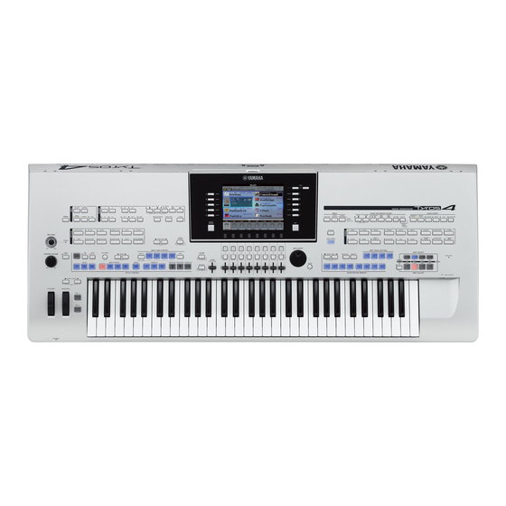
Page 6: Panel Layout (Tyros4)
Tyros4 PANEL LAYOUT (Tyros4) • Top Panel q [MIC GAIN] control !1 [SONG] buttons w [MASTER VOLUME] control !2 [STYLE] category selection buttons e [DEMO] button !3 [STYLE CONTROL] buttons r [FADE IN/OUT] button !4 [TEMPO] buttons t [UPPER OCTAVE] buttons... - Page 7 Tyros4 @1 [MENU] buttons @2 [AUDIO RECORDER/PLAYER] buttons @3 [VOICE EFFECT] buttons @4 [INTERNET] button @5 [MUSIC FINDER] button @6 [VOICE] category selection buttons @7 [REGISTRATION MEMORY] buttons @8 [ONE TOUCH SETTING] buttons @9 [PART SELECT] buttons #0 [PART ON/OFF] buttons...
-
Page 8: Panel Layout (Trs-Ms04)
Tyros4 • Rear Panel q [TO RIGHT SPEAKER] jack o [LINE OUT] jacks w [LAN] terminal !0 [AUX IN/LOOP RETURN] jacks e [USB TO HOST] terminal !1 [AUX OUT/LOOP SEND] jacks r [USB TO DEVICE] terminal !2 [MIC] jack t [ASSIGNABLE FOOT PEDAL] jacks... -
Page 9: Circuit Board Layout
Tyros4 CIRCUIT BOARD LAYOUT • Rear Side AJACK DJACK • Lower Case Side POWER SUPPLY UNIT SPOR SPOL HARD DISK DRIVE UNIT DJACK AJACK EMKS-FD MK61L KEYBOARD ASSEMBLY MKH-D (E-BUS) - Page 10 Tyros4 • Upper Case Side WHEEL ASSEMBLY MODULATION PNLS PITCH BEND MICVR LCD UNIT • LCD Unit CRYSTAL DISPLAY...
-
Page 11: Disassembly Procedure (Tyros4)
Tyros4 DISASSEMBLY PROCEDURE (Tyros4) Precautions • If you want to turn the instrument or upper case • During reassembly, reinstall the adhesive tape, unit upside down, prepare supporting materials cord holder, GND wire and ferrite core that were and put the both end portions of the instrument removed during disassembly as they were before or upper case unit on the supporting materials. - Page 12 Tyros4 Separation of Upper Case Unit and UPPER CASE UNIT Lower Case Unit (The required: About 5 minutes). Remove the four (4) screws marked [S12] and seventeen (17) screws marked [S14A], lift the rear side of the upper case unit a little, pull it toward you a little ①...
- Page 13 Tyros4 DM Circuit Board • Removing Flash Memory Expansion Module (Time Required: About 8 minutes) Loosen the screws with your hand. If there is a fl ash memory expansion module inserted into the expansion module socket, remove the four (4) screws marked [S02A] to remove the DIMM cover and loosen the two (2) screws marked [A] to remove the fl...
-
Page 14: Power Supply Unit
Tyros4 • Rear View [S04D] [S21] [S04D] [S04B] [S04B] [S04B] [S04A] [S04A] LOWER CASE UNIT • Top View DJACK AJACK [S03G] [S03B] SPOR SPOL [S03I ] HARD DISK DRIVE UNIT Fig. 5 AC Lower Frame Assembly AC Upper Frame Assembly... - Page 15 Tyros4 [S03H] ACIN Connector Assembly (Time Required: About 7 minutes) Separate the upper case unit and lower case unit. (See procedure 1.) Remove the AC upper frame assembly. (See procedure 5.) Remove the four (4) screws marked [S04C] and the screw marked [S11B].
- Page 16 Tyros4 • Top View VOLUME KNOB (MIC GAIN) UPPER CASE UNIT ENCODER KNOB LCD UNIT SLIDER KNOB (ASSIGN) SLIDER KNOB [1]-[8] MASTER VOLUME KNOB Fig. 6 PROTECT SHEET PNC • Bottom View [S05K] PANEL STAY (A) PANEL STAY (A) ENC ASSEMBLY...
- Page 17 Tyros4 • Bottom View WHEEL ASSEMBLY UPPER CASE UNIT (MODULATION) [S05N] [S05G] [S05F] PANEL STAY (B) WHEEL ASSEMBLY (PITCH BEND) [S05M] [S05N] [S05L] [S05M] MICVR LCD UNIT [S05E] Fig. 10 PNLS Circuit Board LCD UNIT (Time Required: About 6 minutes) 16-1 Separate the upper case unit and lower case unit.
- Page 18 Tyros4 LCD Lower Case Assembly and Gear LCD Unit (Time Required: About 7 minutes) 20-1 Separate the upper case unit and lower case unit. (Time Required: About 7 minutes) 21-1 Separate the upper case unit and lower case unit. (See procedure 1.) (See procedure 1.)
- Page 19 Tyros4 LCL Circuit Board Crystal Display (Time Required: About 7 minutes) (Time Required: About 7 minutes) 22-1 Separate the upper case unit and lower case unit. 24-1 Separate the upper case unit and lower case unit. (See procedure 1.) (See procedure 1.) 22-2 Remove the LCD unit.
- Page 20 Tyros4 Keys (White and Black Keys) 25-3 Remove the screw marked [MS13] and two (2) screws 26-1 Separate the upper case unit and lower case unit. marked [MS03]. The data line filter and two (2) cord (See procedure 1.) holders can then be removed from the keyboard 26-2 Remove the MK unit.
- Page 21 Tyros4 KEY SPRING KEY GUIDE CAP Photo 6 Table 1 KEY STOPPER L KEY STOPPER H KEY STOPPER 61 REMOVE SCREW [240A] X 2, [240B] X 1 [240B] X 1, [240C] X 2 [240D] X 2 KEY STOPPER H KEY STOPPER 61...
- Page 22 Tyros4 RUBBER CONTACT CONTACT (LONG) CONTACT (SHORT) RUBBER CONTACT Fig. 21 Photo 7 Table 2 RUBBER CONTACT RUBBER CONTACT RUBBER CONTACT RUBBER CONTACT RUBBER CONTACT 13KEY 12KEY A 12KEY B 12KEY C 12KEY D MK61L MK61L MK61L MKH-D MKH-D APPLICATION CIRCUIT BOARD...
- Page 23 Also make sure to close the LCD panel and disconnect a USB device from the [USB TO DEVICE] terminal. Turn the Tyros4 face down on a blanket or some soft surface, giving you direct access to the bottom of the instrument.
-
Page 24: Disassembly Procedure (Trs-Ms04)
TRS-MS04 DISASSEMBLY PROCEDURE (TRS-MS04) AC Cord (Time required: About 3 minutes) Remove the eight (8) screws marked [A]. The rear panel Remove the cord bushing from the rear panel. The AC cord can then be removed. (Fig.1) can then be removed. (Fig.1) When reinstalling the rear panel, confirm that the When reinstalling the rear panel, confirm that the packing packing is not damaged to avoid air leakage. -
Page 25: Installing The Optional Flash Memory Expansion Module
INSTALLING THE OPTIONAL FLASH MEMORY EXPANSION MODULE Installing an optional fl ash memory expansion module to the Tyros4 allows you to import Wave fi les on a USB storage device or hard disk drive, letting you create your own original Voices, Normal Voices and Drum Voices. (For informatio on creating original Voices, re- fer to the Reference Manual on the website.) This section explains how to install an expansion module to the Tyros4. - Page 26 Remove the four screws from the cover. reverse order. Check that the installed module is functioning (Rear side) properly. 6-1 Set the Tyros4 right-side up, and then turn the power on. 6-2 Call up the Format operation display. [VOICE CREATOR] g [E] EXPANSION MODULE...
-
Page 27: Lsi Pin Description
Tyros4 LSI PIN DESCRIPTION AK4396VF-E2 (X8324A00) DAC (Digital to Analog Converter) ............36 AK5381VT-E2 (X5219A0R) ADC (Analog to Digital Converter) ............28 AX88796BLF (YC258A00) LAN CONTROLLER ................37 BH7236AF-E2 (XS062A00) RGB ENCODER ..................36 FIN1215MTDX (YC491A00) LVDS SERIALIZER/DE-SERIALIZER............37 FIN1216MTDX (YC492A00) LVDS SERIALIZER/DE-SERIALIZER............28 HD6433693B14HV (X480120R) E-VKS ....................27 ISP1760BE (X8288A00) USB2.0 HOST CONTROLLER ..............31... - Page 28 Tyros4 AK5381VT-E2 (X5219A0R) ADC (Analog to Digital Converter) DM: IC952 NAME NAME FUNCTION FUNCTION AINR Rch Analog input pin SDTO Audio serial data output pin AINL Lch Analog input pin LRCK Output channel clock pin CKS1 Mode select 1 pin...
- Page 29 Tyros4 YGV628B-VZ (X6356B00) RGB CONTROLLER AVDP7 DM: IC603 NAME FUNCTION NAME FUNCTION SA13 Video memory address bus Digital power supply +3.3 V CPU address bus SA11 SA12 Digital power supply +3.3 V Video memory address bus CPU address bus SA10...
- Page 30 Tyros4 MB87S1280 (X6363A00) SSP1 DM: IC902 NAME FUNCTION NAME FUNCTION WAITN Wait for external CPU MD[7] Data bus(ARM,DSP -> memory) IRQN_OUT Output of interrupt information MD[6] Data bus(ARM,DSP -> memory) VDDE VDDE +3.3V MD[5] SCANSW[4] MD[4] SCANSW[3] MD[3] Data bus(ARM,DSP -> memory)
- Page 31 Tyros4 ISP1760BE (X8288A00) USB2.0 HOST CONTROLLER DM: IC500 NAME FUNCTION NAME FUNCTION OC3_N Port 3 analog (5 V input) and digital overcurrent input DATA20 Data bit 20 input and output REF5V 5 V reference input for analog OC detector DATA21...
- Page 32 Tyros4 T6TJ3XBG-0001 ( X8940A00 ) SWP51L ( Tone Generator ) DM: IC700, 701 OUTER OUTER NAME FUNCTION NAME FUNCTION VDDC Ground Power supply +1.5 V VDDC HRD2 Ground HRD0 HRD9 CD14 DRAM data bus HRD11 CD13 Data bus of internal register...
- Page 33 Tyros4 OUTER OUTER NAME FUNCTION NAME FUNCTION LMD11 VDDC LMD4 Wave memory data bus (Lower 16 bit) VDDC LMD3 AC10 VDDC Power supply +1.5 V VDDS Power supply +3.3 V AC11 VDDC AC12 VDDC AC13 VDDC AC14 VDDS Ground AC15...
- Page 34 Tyros4 R8A77310D333BG (YC170A00) MAIN CPU DM: IC1 OUTER OUTER NAME FUNCTION NAME FUNCTION AV33 3.3 V power supply for USB reference power supply circuit Always used I/O power supply (3.3V) Ground XTAL Clock output EXTAL External clock input Ground PTG3/AUDATA3...
- Page 35 Tyros4 R8A77310D333BG (YC170A00) MAIN CPU DM: IC1 OUTER OUTER NAME FUNCTION NAME FUNCTION AA12 AA13 Ground Ground AA14 AA15 AA16 I/O power supply (3.3 V) Internal power supply (1.2 V) AA17 Ground AA18 HPD56/PTN0 AA19 HPD55/PTB7 AA20 Ground SDRAM upper data bus / Port...
- Page 36 Tyros4 AK4396VF-E2 (X8324A00) DAC (Digital to Analog Converter) DM: IC950, 951 NAME FUNCTION NAME FUNCTION Digital ground CMOS/TTL level select Digital power supply +3.3 V VREFL Low level voltage reference input MCLK Master clock input VREFH High level voltage reference input...
- Page 37 Tyros4 AX88796BLF (YC258A00) LAN CONTROLLER DM: IC400 NAME FUNCTION NAME FUNCTION VCC3A3 Power supply for analog circuit (+3.3V DC) GND3A3 Power supply for analog circuit (+0V DC or Ground power) TPI+ Twisted pair receive input, positive Twisted pair receive input, negative...
-
Page 38: Circuit Boards
Tyros4 CIRCUIT BOARDS AJACK Circuit Board (YC340B0) ..................40 CK Circuit Board (YC341C0) ....................64 DJACK Circuit Board (YC341C0) ..................46 DM Circuit Board (YC134D0) ..................42/44 EMKS-FD Circuit Board (X6577A0) ................58/59 EN Circuit Board (YC489A0) ....................49 HP Circuit Board (YC341C0) ....................39 LCL Circuit Board (YC270B0) .................. - Page 39 Tyros4 SPOL Circuit Board to AJACK-CN400 SPOR Circuit Board to AJACK-CN401 Component side Pattern side Component side HP Circuit Board to AJACK-CN500 Pattern side Component side Pattern side HP, SPOL, SPOR: 2NA-WT90150...
- Page 40 Tyros4 AJACK Circuit Board not installed to HP-CN100 to SPOR-CN80 to MICVR-CN302 to DM-CN952 to SPOL-CN70 2NA-WT90140...
- Page 41 Tyros4 to MICVR-CN301 to DM-CN951 to DM-CN950 Component side Pattern side 2NA-WT90140...
- Page 42 Tyros4 DM Circuit Board to AJACK-CN200 not installed to CK-CN96 to DJACK-CN40 to DJACK-CN10 to AJACK-CN101 to EMKS-FD-CN4 to AJACK-CN100 2NA-WT75980...
- Page 43 Tyros4 not installed to LCR-CN202 to USB-CN201 to PNR-CN4 to LCL-CN101 to HDD-UNIT to POWER SUPPLY UNIT-CN2 to DJACK-CN60 to CK-CN94 IC904 48P-TSOP Component side 2NA-WT75980...
- Page 44 Tyros4 DM Circuit Board IC23 48P-TSOP 2NA-WT75980...
- Page 45 Tyros4 to FLASH ROM EXPANSION MODULE This number is the Ethernet MAC Address written on the DM circuit board. If the DM circuit board is replaced, the MAC AB CD EF GH I J KL address will be changed. The MAC address is required to execute the test program through Ethernet.
- Page 46 Tyros4 DJACK Circuit Board to DM-CN600 2NA-WT90150...
- Page 47 Tyros4 to DM-CN3 to DM-CN4 Component side Pattern side 2NA-WT90150...
- Page 48 Tyros4 USB Circuit Board to DM-CN503 Pattern side Component side PNLS Circuit Board to PNL-CN1 Pattern side Component side PNLS: 2NA-WT90240 USB: 2NA-WT90310...
- Page 49 Tyros4 PNC Circuit Board EN Circuit Board to PNR-CN1 Component side Component side PNC, EN: 2NA-WT90280...
- Page 50 Tyros4 PNR Circuit Board to PNL-CN4 to DM-CN901 2NA-WT90310...
- Page 51 Tyros4 Component side 2NA-WT90310...
- Page 52 Tyros4 PNR Circuit Board 2NA-WT90310...
- Page 53 Tyros4 to PNC-CN2 Pattern side 2NA-WT90310...
- Page 54 Tyros4 PNL Circuit Board 2NA-WT90240...
- Page 55 Tyros4 not installed to PNR-CN2 Component side 2NA-WT90240...
- Page 56 Tyros4 PNL Circuit Board to CK-CN91 to LCL-CN152 2NA-WT90240...
- Page 57 Tyros4 to PNLS-CN202 to WHEEL ASSEMBLY Pattern side 2NA-WT90240...
- Page 58 Tyros4 MKH-D Circuit Board to EMKS-FD-CN6 to MK61L-CN1 to EMKS-FD-CN5 EMKS-FD Circuit Board not installed to DM-CN902 not installed Component side LCL Circuit Board to DM-CN300 DIRECT ACCESS Component side EMKS-FD: WE62240 LCL: 2NA-WT78420 MKH-D: 2NAKZ-WD78540...
- Page 59 Tyros4 to PC SENSOR Component side EMKS-FD Circuit Board to MKH-D-CN3 to MKH-D-CN1 Pattern side LCL Circuit Board to TFT LCD Panel 7.5 inch VGA to LCR-CN251 to PNL-CN2 EMKS-FD: WE62240 Pattern side LCL: 2NA-WT78420 MKH-D: 2NAKZ-WD78540...
- Page 60 Tyros4 MKH-D Circuit Board AFTER TOUCH SENSOR LCR Circuit Board to DM-CN302, CK-CN93 Component side LCR: 2NA-WT78420 MKH-D: 2NAKZ-WD78540...
- Page 61 Tyros4 to EMKS-FD-CN6 to EMKS-FD-CN5 Pattern side LCR Circuit Board to LCL-CN151 to TFT LCD Panel 7.5 inch VGA (Backlight) Pattern side LCR: 2NA-WT78420 MKH-D: 2NAKZ-WD78540...
- Page 62 Tyros4 MK61L Circuit Board N.C. to MKH-D-CN4 Component side 2NAKZ-WD80020...
- Page 63 Tyros4 MK61L Circuit Board Pattern side 2NAKZ-WD80020...
- Page 64 Tyros4 CK Circuit Board to POWER SUPPLY UNIT-CN6 to POWER SUPPLY to POWER SUPPLY UNIT-CN5 UNIT-CN3 to DM-CN953 to DM-CN500 to PNL-CN3 Pattern side to LCR-CN202 Component side MICVR Circuit Board to AJACK-CN102 to AJACK-CN201 Component side Pattern side 2NA-WT90150...
-
Page 65: Test Program
0 dBu = 0.775 Vrms Starting up the test program * Install the fl ash memory expansion module before turning on the power of Tyros4. (P. 25) * Before starting checking, format the HDD referring to the “FORMATTING HDD” (P. 101). - Page 66 Tyros4 Start-up screen (normal state) Start-up screen (when an error is detected) TEST TEST SwErr:xxx.yyy Device Connection Check Device Connection Check [Int.HDD]:Device found [Int.HDD]:No Device [Exp.Module]:Device found [Exp.Module]:No Device xxx and yyy : Codes of pressed switch “SwErr” (A panel switch is being pressed. Displays up to two codes for panel switch held down in four fi gures in hexadecimal notation.) “[Int.
- Page 67 Tyros4 • Test Program Item List Number Check item Displayed Message Automatic check Version indication Version Simplifi ed check of all memories Memory Check1 All Simplifi ed check of ROM ROM Check1 Simplifi ed check of RAM RAM Check1 Simplifi ed check of Backup Flash ROM BACKUP ROM Check1 Simplifi...
- Page 68 002:Memory Check1 All If ErP is supported, the Model Name is "TYROS4 (E)-r". MAIN DATA ROM (IC19 ) NG If ErP is not supported, the Model Name is "TYROS4 (E)" without the suffi x “-r”. "0.00" will be shown if the version is not recognized correctly. In case of NG (Example)
- Page 69 Tyros4 Test 3 Test 4 Function: Simplifi ed check of ROM Function: Simplifi ed check of RAM Description: Description: Executes Read test (checksum test) of ROM. Executes Read/Write test (connection check) of RAM. Executes Write pin check of Program Flash ROM as well.
- Page 70 Tyros4 Test 5 Test 6 Function: Simplifi ed check of Backup ROM Function: Simplifi ed check of Wave ROM Description: Description: Executes Read/Write test (connection check) of Backup Flash Executes Read test (checksum test) of Wave ROM. ROM. It will take about 15 seconds for the check.
- Page 71 Tyros4 Test 7 Test 8 Function: Simplifi ed check of Effect RAM Function: Sound check of the Tone Generator 1 Description: Description: Checks RAM that works for Effect. Sequentially outputs sounds starting from lower keys by Displayed Message: switching the channel of the sound source at the SWP51 L...
- Page 72 Tyros4 Test 9 Test 10 Function: Sound check of the Tone Generator 2 Function: SSP1 check Description: Description: Sequentially outputs sounds starting from lower keys by Executes the serial communications check of Main CPU and switching the channel of the sound source at the SWP51L SSP1 chip.
- Page 73 Tyros4 Test 11 Test 12 Function: Pitch check Function: Output Level R check Description: Description: Set the [MASTER VOLUME] to the maximum level. Connect a level meter (JIS-C curve) to each jack. ([PHONES] Connect a frequency counter to the [PHONES] jack. (Either L or R) L, R, [LINE OUT MAIN] L/L+R, R, [AUX OUT/LOOP SEND] (Load should be 33 Ω.
- Page 74 Tyros4 Test 13 Test 14 Function: Output Level L check Function: Output Level Sub-1 check Description: Description: Connect a level meter (JIS-C curve) to each jack. ([PHONES] Set the [MASTER VOLUME] to the maximum level. L, R, [LINE OUT MAIN] L/L+R, R, [AUX OUT/LOOP...
- Page 75 Tyros4 Displayed Message: 015:Output Sub−2 Check −− 016:EQ Low Check When a sound is being produced. Supplement: Selected screen Sound is stopped when the test item is quit. Noise Level: Set the [MASTER VOLUME] to the maximum level. Connect a level meter to the L/R of [PHONES] terminal.
- Page 76 Tyros4 Supplement: Sound is stopped when the test item is quit. 019:SP MUTE Check OFF Test 18 Function: EQ (High) frequency check Description: The sine wave of about 4,195 Hz (C7) is output from the [LINE OUT] jacks (MAIN L/L+R, MAIN R, SUB1, SUB2).
- Page 77 Tyros4 ¡To input a signal into the Cold side (pin No. 3), short the Hot side (pin No. 2) to GND and input a signal between Cold and GND. 020:MUTE Check Displayed Message: OFF 021:MIC Check During MUTE OFF 020:MUTE Check Selected screen ON...
- Page 78 Tyros4 ¡Amount of volume decay: Change the [AUX IN/LOOP RETURN TRIM VOLUME] to the minimum level with the other setups remained as above. 022:SIOF Check Measure output terminals. −− • LINE OUT MAIN L/L+R: -75.0 dBu or less • LINE OUT MAIN R: -75.0 dBu or less...
- Page 79 Tyros4 023:SW, LED Check 023:SW, LED Check Dial Down Push TEMPO − TEMPO DOWN On 50 The specifi ed switch is pressed. [DATA ENTRY] dial test 023:SW, LED Check 023:SW, LED Check END Push TEMPO − NG [TEMPO + ] On 52 A wrong switch is pressed. Test completed (Detection of On) Supplement: If an unspecifi ed switch is pressed, a sound corresponding to the switch will be played.
- Page 80 Tyros4 Test 26 Function: Blue and Green LEDs On check Description: 024:All LED On Check Turns on all the blue and green panel LEDs. (Two-colored −− LEDs will light in green.) Displayed Message: 026:Blue/Green LED On Check During checking Supplement: There are two lighting areas and the areas will be switched as the TAB [ ]/[#] key is pressed.
- Page 81 Tyros4 Test 29 Function: Whole LCD OFF check Description: 027:Other LED On Check Turns off all the dots on the LCD. (The whole screen will be −− white) Displayed Message: 029:All LCD Off Check During checking Supplement: The LEDs will go off after exiting the test item.
- Page 82 Tyros4 Displayed Message: 031:Pitch Bend Wheel Check RGB pattern Selected screen 031:Pitch Bend Wheel Check Pitch Bend Center NG 62 Rainbow pattern When the checking is started In case of NG (When the center value is not detected) 031:Pitch Bend Wheel Check Pitch Bend Down Flicker noise pattern 64 When the checking is started...
- Page 83 Tyros4 031:Pitch Bend Wheel Check 032:Modulation Wheel Check Pitch Bend Center Modulation Up 127 xxx Detection of the maximum value When the checking is started (xxx: Indicates current value) 031:Pitch Bend Wheel Check OK 032:Modulation Wheel Check Modulation Down 64 127 In case of OK (When the center value is detected) Detection of the maximum value...
- Page 84 Tyros4 Test 33 Function: Slider check Description: 033:Slider Check Slide the 9 sliders one by one in the order of Max (255) to Min (0) and check that the operation is detected. [ASSIGN] OK When checking a slider, current value will be shown.
- Page 85 Tyros4 Test 34 Function: Pedal 1 check Description: Detects Max/Min of the pedal 1. 034:Pedal1 Check Execute the test after connecting a foot pedal (FC7) to the Pedal1 Out [ASSIGNABLE FOOT PEDAL 1] terminal. q "Pedal 1 Down": Depress the pedal. (The sine wave C3 note sound will be produced.) w "Pedal 1 Up":...
- Page 86 Tyros4 Displayed Message: 035:Pedal2 Check No Pedal 035:Pedal2 Check When unconnected (No foot pedal is connected) Selected screen Supplement: Use an FC7 pedal for the checking. Test 36 035:Pedal2 Check Function: Pedal 3 check Pedal2 Down Description: Detects Max/Min of the pedal 3. Execute the test after connecting a foot pedal (FC7) to the [ASSIGNABLE FOOT PEDAL 3] terminal.
- Page 87 Tyros4 Test 37 Function: MIDI check Description: Checks transmission/reception of signals with the [MIDI IN] 036:Pedal3 Check Pedal3 Up and [MIDI OUT] terminals connected with a MIDI cable in a loop. (Start checking with the MIDI terminals connected with a MIDI cable in a loop.) Connect [MIDI A OUT] to [MIDI A IN] and [MIDI B OUT] to [MIDI B IN] with MIDI cables.
- Page 88 Tyros4 Level check: Set the [MASTER VOLUME] to the maximum level. Connect a level meter (JIS-C curve) to [LINE OUT MAIN 037:MIDI Check L/L+R] terminal. MIDI−A Check NG Load should be 10 k Ω. MIDI−B Check OK q When the test is started. LINE OUT MAIN L/L+R: +9.5±2 dBu w When an audio cable is inserted to [AUX OUT/LOOP SEND L/L+R] terminal.
- Page 89 Tyros4 Test 39 Function: Sub Out connection check Description: 039:Sub Out Check [LINE OUT SUB 1] and [LINE OUT SUB 2] function check OK using an audio cable. The C3 note will be outputted when an audio cable is inserted to the [LINE OUT SUB] terminals, and C4 note will output when an audio cable is disconnected from the terminals.
- Page 90 Tyros4 Test 41 Function: Video Out check (PAL RGB) Description: Conducts RGB (PAL) test of the [VIDEO OUT] terminal. Connect a color CRT monitor that can display in NTSC and RGB PAL systems to the [VIDEO OUT] terminal with a video cable (75Ω...
- Page 91 Tyros4 043:USB to Device/Host Check 043:USB to Device/Host Check Device−Host (Rear) OK Device−Host (Front) NG In case of OK ([USB TO DEVICE] (rear side) and [USB TO HOST] In case of NG ([USB TO DEVICE] (front side) and [USB TO HOST] 043:USB to Device/Host Check 043:USB to Device/Host Check Device−Host (Rear) NG OK In case of NG ([USB TO DEVICE] (rear side) and [USB TO HOST] In case of OK 043:USB to Device/Host Check...
- Page 92 Tyros4 Test 44 Function: USB Storage Device check Description: 044:USB Storage Device Check Connect a USB Storage device and check if it can be used. NG (Reads every 100 sectors from sector 0 and conducts sector read/write tests at ten points.) * Please carry out this test twice, as the [USB TO DEVICE] terminals on the front and rear panels both have to be checked.
- Page 93 (Starting from sector 0, a read/write test will be performed at 10 places in 100-sector units.) A HDD formatted using Tyros4 must be used. Also make sure nothing is connected to the other [USB TO DEVICE] terminal before executing the test.
- Page 94 Description: Description: Conducts signal communication checking with the [LAN] Judges connected keyboard type and indicated keyboard terminal of the Tyros4 and a router for checking connected name. with a LAN cable. (Starts checking with the instrument Displayed Message: connected with the LAN cable.) It will take about 20 seconds for the check.
- Page 95 Tyros4 Test 48 Test 49 Function: Touch check Factory Inspection Only Description: Press the C3 key and press that until after touch will be activated. Test 50 Indicates initial touch (velocity)/after touch value of 0 to 127 Function: Full check of ROM decimally on the LCD.
- Page 96 Tyros4 Test 51 Test 52 Function: Full check of RAM Function: Full check of backup ROM Description: Description: Executes Read/Write test (connection check) of RAM. Executes Read/Write test of the entire blocks of Backup Flash Displayed Message: ROM. It will take about 6 minutes for the check.
- Page 97 Tyros4 Test 53 Test 54 Function: Full check of Wave ROM Function: Full check of Effect RAM Description: Description: Executes Read test (full address checksum test) of Wave ROM. Full address checksum inspection of EffectRAM As the Wave ROM is shared by TG1 (Master) and TG2 (Slave), It will take about 1 minute for the check.
-
Page 98: Initial Setting
Quits the test mode and restarts. (Restarting should be conducted automatically. Check if the restarting is conducted.) Test 61 Function: Factory Set Displayed Message: Description: Restores the Tyros4 to the factory initial setup. (Sets the initial data to the Flash ROM.) Displayed Message: 062:Test Exit 061:Factory Set Selected screen... - Page 99 Tyros4 • Switch Test Sequence Turn SW Name / Display Note Number Turn SW Name / Display Note Number Turn SW Name / Display Note Number TYPE SELECT 57 MAIN B 113 HARMONY ECHO MIC SETTING 58 MAIN C 114 INITIAL TOUCH...
-
Page 100: Flash Memory Expansion Module Check
Tyros4 FLASH MEMORY EXPANSION MODULE CHECK 1. Install the fl ash memory expansion module to the Tyros4 6. When the Read/Write check is completed successfully, "OK" when the Tyros4's power is turned off. (See page 25.) will be shown in the R/W result fi eld. -
Page 101: Formatting Hdd
======================= Internal HDD Information ======================= Even for an internal HDD formatted on another Tyros4 information will be displayed, but the “Volume Name” will Vender ID I-O DATA be empty or another name than “_TYROS4HDD_” will be... -
Page 102: System Reset
Factory Reset–Restoring the Factory Programmed Settings This function lets you restore the status of the Tyros4 to the original factory settings. Select the desired item to be restored by using [1pq]–[3pq] buttons and add a checkmark to it by pressing the [4 p] (MARK ON) button. - Page 103 Tyros4 Custom Reset–Saving and Recalling Your Original Settings as a Single File For the items below, you can save your Original Settings as a Single File for future recall. Make all desired settings on the instrument. Call up the operation display.
-
Page 104: Os Update
(YSISS URL>>http://plaza.yamaha.co.jp/ysiss/ exindex.nsf) (Insert the USB memory containing only the update program into the USB terminal of the Tyros4.) Tools required for update: 2-2-2 Keep pressing the [START/STOP] button until the USB memory following screen is displayed on the LCD. -
Page 105: Troubleshooting
Press the [TEMPO+] button or turn the [DATA ENTRY] dial clockwise to display “062:Test Exit”. Press the [START/STOP] button to reboot the Tyros4. When the main screen appears normally, the factory set is completed. (Occasionally, it might take a few minutes.) CAUTION: Do not turn the power off before the main 2-2-6 When the installations are fi... -
Page 106: Initializing Internet Setup
Tyros4 INITIALIZING INTERNET SETUP CAUTION This restores the network settings to the default settings. Press the [INTERNET] button. Use the [DATA ENTRY] dial to select “Set the Internet connection,” then press the [ENTER] button to execute. DATA ENTRY ENTER Press the [E] button to select “INITIALIZE SETUP.”... -
Page 107: Data Backup
Tyros4 DATA BACKUP For maximum data security Yamaha recommends that you copy or save your important data to a USB storage device. This provides a convenient backup if the internal memory is damaged. Insert/connect the backup USB storage device (destination). -
Page 108: Display Messages
Please insert the Installer media. Install the installation media. Disconnect the USB memory from when the booter is started. Tyros4 except the installation use. When the installation fi le is undetected Store the installation fi le again and Installer program not found! No installer found. - Page 109 Tyros4 [INSTALLER] Displayed message Meaning Progress/status How to service Data is being loaded. Wait a Now checking. Please wait a moment… Data is being loaded – while. During installing. Wait a Now installing. Please wait a moment… During installation of data –...
- Page 110 Tyros4 [At start] Displayed message Meaning Progress/status How to service Power has not been turned Data is being restored as defect has been Improper power shut down! Backup off normally. Backup data detected in the data backed up in the data fl ash –...
-
Page 111: System Booting Flowchart
Tyros4 SYSTEM BOOTING FLOWCHART SSP1 soft reset If the booting procedure does not IC902 reach to this stage, the following parts might be defective: CPU registers setting • CPU (IC1) Opening screen • SWP51L (IC701) will appear Port initialization /PRG-WP = L (IC16 16pin) - Page 112 Tyros4 If the booting procedure does not reach to this stage, the backup Send a message flash ROM (IC23) might be defective. to SWP51L. Initialize keyboard Keyboard input is not accepted yet. Animation to the Second opening screen will appear.
- Page 113 PARTS LIST CONTENTS OVERALL ASSEMBLY ................2 UPPER CASE UNIT ................4 LOWER CASE UNIT ................7 LCD UNIT ....................10 KEYBOARD ASSEMBLY ............... 12 WHEEL ASSEMBLY ................14 ELECTRICAL PARTS ............... 15-45 Notes : DESTINATION ABBREVIATIONS A : Australian model M : South African model B : British model O : Chinese model...
- Page 114 AC UPPER FRAME ASSEMBLY LOWER CASE UNIT : See page 7. l U model l E, B, P models DIGITAL KEYBOARD DIGITAL KEYBOARD MODEL TYROS4 MODEL TYROS4 120V 110 - 240V 45W 60Hz 45W 50/60Hz MADE IN JAPAN MADE IN JAPAN...
- Page 115 Tyros4 PART NO. DESCRIPTION 部 品 名 REMARKS REF NO. QTY RANK OVERALL ASSEMBLY 総 組 立 Tyros4 OVERALL ASSEMBLY 総 組 立 U U (WU90760) OVERALL ASSEMBLY 総 組 立 E,B,P (WU48040) UPPER CASE UNIT 上 ケ ー ス ユ ニ ッ ト...
- Page 116 Tyros4 UPPER CASE UNIT LCD UNIT: See page 10. WF11020R STABILIZER [42] WHEEL ASSEMBLY: See page 14. WF11020R STABILIZER [42] UC11 UC10 ENC ASSEMBLY...
- Page 117 名 REMARKS REF NO. QTY RANK UPPER CASE UNIT 上 ケ ー ス ユ ニ ッ ト Tyros4 UPPER CASE UNIT 上 ケ ー ス ユ ニ ッ ト (WU61800) WU619300 UPPER CASE 上 ケ ー ス 印 刷 品...
- Page 118 Tyros4 PART NO. DESCRIPTION 部 品 名 REMARKS REF NO. QTY RANK 2 2 7 6 4 9 0 0 ADHESIVE TAPE 12X50m 粘 着 テ ー プ VP83460R FILAMENT TAPE 12X50 粘 着 テ ー プ CB829850 CORD HOLDER S-34B-E 束...
- Page 119 Tyros4 LOWER CASE UNIT LC12 LC11 LC14 LC12 LC14 LC17 LC13 LC13 LC16 LC15 LC18 LC10 U model only LC15 LC17 LC16 LC10 LC11 LC19 LC2a LC2c LC2d LC1a LC6a LC4a LC2b LOWER CASE ASSEMBLY LC19 MK UNIT KEYBOARD ASSEMBLY : See page 12.
- Page 120 名 REMARKS REF NO. QTY RANK LOWER CASE UNIT 下 ケ ー ス ユ ニ ッ ト Tyros4 LOWER CASE UNIT U 下 ケ ー ス ユ ニ ッ ト U U (WU90830) LOWER CASE UNIT 下 ケ ー ス ユ ニ ッ ト E,B,P...
- Page 121 Tyros4 PART NO. DESCRIPTION 部 品 名 REMARKS REF NO. QTY RANK LC10 CONNECTOR ASSEMBLY USB12V XH-XH 2P U S B 1 2 V 束 線 (WU65330) LC11 CONNECTOR ASSEMBLY CK-DM XH-XH 3P C K − D M 束 線...
- Page 122 Tyros4 LCD UNIT LD1a LS03 LCD lower case assembly LS03 LS03...
- Page 123 名 REMARKS REF NO. QTY RANK LCD UNIT L C D ユ ニ ッ ト Tyros4 WU619400 LCD UNIT L C D ユ ニ ッ ト WN137000 LCD UPPER CASE L C D 上 ケ ー ス 塗 装 品...
- Page 124 Tyros4 KEYBOARD ASSEMBLY 400b 400c 400e 400f 400d 400b 220c 220b 220b 220a 210b 210b 210aa 210a...
- Page 125 PART NO. DESCRIPTION 部 品 名 REMARKS REF NO. QTY RANK KEYBOARD ASSEMBLY F S X 鍵 盤 D Tyros4 WD53490R KEYBOARD ASSEMBLY FSX D C61 K6 F S X 鍵 盤 D KEYBOARD FRAME FSX61+STOPPER M K フ レ...
- Page 126 名 REMARKS REF NO. QTY RANK WHEEL ASSEMBLY ホ イ ー ル A s s ’ y Tyros4 WHEEL ASSEMBLY (WN84220) ホ イ ー ル A s s ’ y WN842300 WHEEL FRAME ホ イ ー ル フ レ ー ム...
-
Page 127: Electrical Parts
PART NO. DESCRIPTION 部 品 名 REMARKS REF NO. QTY RANK ELECTRICAL PARTS 電 気 部 品 Tyros4 WT901300 CIRCUIT BOARD AJACK A J A C K シ ー ト (WT90140)(YC340B0) WT902000 CIRCUIT BOARD C K シ ー ト (WT90150)(YC341C0) - Page 128 Tyros4 AJACK PART NO. DESCRIPTION 部 品 名 REMARKS REF NO. QTY RANK C472 VS49070R ELECTROLYTIC CAPACITOR 47.0 16.0V TP ケ ミ コ ン 5 L C473 V 8 0 8 5 4 0 0 CERAMIC CAPACITOR-B (CHIP) 0.1000 25V K RECT.
- Page 129 Tyros4 AJACK PART NO. DESCRIPTION 部 品 名 REMARKS REF NO. QTY RANK D500 VB941200 DIODE 1SS133,1SS176 TE-5 ダ イ オ ー ド EM100 V I 2 4 3 1 0 0 EMI FILTER DSS6NB32A271Q93A L C フ ィ ル タ ー...
- Page 130 Tyros4 AJACK PART NO. DESCRIPTION 部 品 名 REMARKS REF NO. QTY RANK R208 RF457470 CARBON RESISTOR (CHIP) 47.0K D RECT. チ ッ プ 抵 抗 R209 RF454180 CARBON RESISTOR (CHIP) 18.0 D RECT. チ ッ プ 抵 抗 R210 RF456220 CARBON RESISTOR (CHIP) 2.2K D RECT.
- Page 131 Tyros4 AJACK and CK/DJACK/HP/SPOL/SPOR PART NO. DESCRIPTION 部 品 名 REMARKS REF NO. QTY RANK R503 RD15433R CARBON RESISTOR (CHIP) 33.0 1/4 J TP チ ッ プ 抵 抗 R505 RD357100 CARBON RESISTOR (CHIP) 10.0K 63M J RECT. チ ッ...
- Page 132 Tyros4 CK/DJACK/HP/SPOL/SPOR PART NO. DESCRIPTION 部 品 名 REMARKS REF NO. QTY RANK WT901600 CIRCUIT BOARD DJACK D J A C K シ ー ト (WT90150)(YC341C0) WT901700 CIRCUIT BOARD H P シ ー ト (WT90150)(YC341C0) WT901800 CIRCUIT BOARD SPOL S P O L シ ー ト...
- Page 133 Tyros4 CK/DJACK/HP/SPOL/SPOR and DM PART NO. DESCRIPTION 部 品 名 REMARKS REF NO. QTY RANK VB835000 COIL 20uH FL05RD200AT コ イ ル 2 0 U VY65720R CHIP INDUCTANCE 600 BK1608HM601-T チ ッ プ イ ン ダ ク タ VY65720R CHIP INDUCTANCE 600 BK1608HM601-T チ...
- Page 134 Tyros4 PART NO. DESCRIPTION 部 品 名 REMARKS REF NO. QTY RANK US625100 CERAMIC CAPACITOR-BJ (CHIP) 0.100 10V K RECT. チ ッ プ セ ラ( B J ) US634220 CERAMIC CAPACITOR-B (CHIP) 0.022 16V K RECT. チ ッ プ セ ラ( B )...
- Page 135 Tyros4 PART NO. DESCRIPTION 部 品 名 REMARKS REF NO. QTY RANK C419 US625100 CERAMIC CAPACITOR-BJ (CHIP) 0.100 10V K RECT. チ ッ プ セ ラ( B J ) C420 WG888300 MONOLITHIC CERAMIC CAP. (CHIP) 10.0 6.3V K TP チ ッ プ 積 層 セ ラ コ ン...
- Page 136 Tyros4 PART NO. DESCRIPTION 部 品 名 REMARKS REF NO. QTY RANK C630 US625100 CERAMIC CAPACITOR-BJ (CHIP) 0.100 10V K RECT. チ ッ プ セ ラ( B J ) -637 US625100 CERAMIC CAPACITOR-BJ (CHIP) 0.100 10V K RECT. チ ッ プ セ ラ( B J )...
- Page 137 Tyros4 PART NO. DESCRIPTION 部 品 名 REMARKS REF NO. QTY RANK C1020 US625100 CERAMIC CAPACITOR-BJ (CHIP) 0.100 10V K RECT. チ ッ プ セ ラ( B J ) C1021 WG888300 MONOLITHIC CERAMIC CAP. (CHIP) 10.0 6.3V K TP チ ッ プ 積 層 セ ラ コ ン...
- Page 138 Tyros4 PART NO. DESCRIPTION 部 品 名 REMARKS REF NO. QTY RANK C1236 US625100 CERAMIC CAPACITOR-BJ (CHIP) 0.100 10V K RECT. チ ッ プ セ ラ( B J ) -1267 US625100 CERAMIC CAPACITOR-BJ (CHIP) 0.100 10V K RECT. チ ッ プ セ ラ( B J )...
- Page 139 Tyros4 PART NO. DESCRIPTION 部 品 名 REMARKS REF NO. QTY RANK X3693A01 IC SN74LV245APWR I C TRANSCEIVER X3693A01 IC SN74LV245APWR I C XU797B01 IC TC74VHC245FT(EL,K) I C XU797B01 IC TC74VHC245FT(EL,K) I C IC10 XV893A0R IC TC74VHC139FT(EL) I C DECODER...
- Page 140 Tyros4 PART NO. DESCRIPTION 部 品 名 REMARKS REF NO. QTY RANK IC952 X5219A0R IC AK5381VT-E2 I C ADC IC954 X3505A00 IC NJM2068M-D(TE2) I C OP AMP -956 X3505A00 IC NJM2068M-D(TE2) I C OP AMP IC957 X9293A00 IC R1172H151D-T1-F I...
- Page 141 Tyros4 PART NO. DESCRIPTION 部 品 名 REMARKS REF NO. QTY RANK RD457100 CARBON RESISTOR (CHIP) 10.0K 63M J RECT. チ ッ プ 抵 抗 RD457100 CARBON RESISTOR (CHIP) 10.0K 63M J RECT. チ ッ プ 抵 抗 RD454680 CARBON RESISTOR (CHIP) 68.0 63M J RECT.
- Page 142 Tyros4 PART NO. DESCRIPTION 部 品 名 REMARKS REF NO. QTY RANK R252 RD454680 CARBON RESISTOR (CHIP) 68.0 63M J RECT. チ ッ プ 抵 抗 -255 RD454680 CARBON RESISTOR (CHIP) 68.0 63M J RECT. チ ッ プ 抵 抗...
- Page 143 Tyros4 PART NO. DESCRIPTION 部 品 名 REMARKS REF NO. QTY RANK R617 RD454470 CARBON RESISTOR (CHIP) 47.0 63M J RECT. チ ッ プ 抵 抗 -619 RD454470 CARBON RESISTOR (CHIP) 47.0 63M J RECT. チ ッ プ 抵 抗...
- Page 144 Tyros4 PART NO. DESCRIPTION 部 品 名 REMARKS REF NO. QTY RANK R780 RD45747R CARBON RESISTOR (CHIP) 47.0K 63M J RECT. チ ッ プ 抵 抗 R783 RD45000R CARBON RESISTOR (CHIP) 0.00 63M J RECT. チ ッ プ 抵 抗...
- Page 145 Tyros4 PART NO. DESCRIPTION 部 品 名 REMARKS REF NO. QTY RANK R1041 RD456470 CARBON RESISTOR (CHIP) 4.7K 63M J RECT. チ ッ プ 抵 抗 R1042 RD457120 CARBON RESISTOR (CHIP) 12.0K 63M J RECT. チ ッ プ 抵 抗...
- Page 146 Tyros4 DM and EN/PNC PART NO. DESCRIPTION 部 品 名 REMARKS REF NO. QTY RANK -403 WH206600 RESISTOR ARRAY 68X4 抵 抗 ア レ イ RA500 WH213400 RESISTOR ARRAY 47K X4 抵 抗 ア レ イ -503 WH213400 RESISTOR ARRAY 47K X4 抵...
- Page 147 Tyros4 EN/PNC and LCL/LCR PART NO. DESCRIPTION 部 品 名 REMARKS REF NO. QTY RANK HF45510R CARBON RESISTOR 100.0 1/4 J AX TP カ ー ボ ン 抵 抗 HF45510R CARBON RESISTOR 100.0 1/4 J AX TP カ ー ボ...
- Page 148 Tyros4 LCL/LCR and MICVR/PNL/PNLS PART NO. DESCRIPTION 部 品 名 REMARKS REF NO. QTY RANK L101 WT761600 CHIP COIL DLW31SN222SQ2 32 チ ッ プ チ ョ ー ク コ イ ル L102 RD350001 CARBON RESISTOR (CHIP) 0 63M J RECT.
- Page 149 Tyros4 MICVR/PNL/PNLS PART NO. DESCRIPTION 部 品 名 REMARKS REF NO. QTY RANK UF11822R ELECTROLYTIC CAPACITOR (CHIP) 220 6.3V チ ッ プ ケ ミ コ ン US064100 CERAMIC CAPACITOR-B (CHIP) 0.0100 50V K RECT. チ ッ プ セ ラ( B )...
- Page 150 Tyros4 MICVR/PNL/PNLS PART NO. DESCRIPTION 部 品 名 REMARKS REF NO. QTY RANK WM469900 LED GREEN HFG223P-BW14 L E D STYLE (DANCE) LD10 WM469900 LED GREEN HFG223P-BW14 L E D STYLE (MOVIE & SHOW) LD11 WN414500 LED HFR8239P(P1D2)-BW1 L E...
- Page 151 Tyros4 MICVR/PNL/PNLS PART NO. DESCRIPTION 部 品 名 REMARKS REF NO. QTY RANK RD15447R CARBON RESISTOR (CHIP) 47.0 1/4 J TP チ ッ プ 抵 抗 RD357100 CARBON RESISTOR (CHIP) 10.0K 63M J RECT. チ ッ プ 抵 抗 RD357100 CARBON RESISTOR (CHIP) 10.0K 63M J RECT.
- Page 152 Tyros4 MICVR/PNL/PNLS and MK61L and MKH-D PART NO. DESCRIPTION 部 品 名 REMARKS REF NO. QTY RANK SW26 WG31840R TACT SWITCH SKRGAMD010 タ ク ト S W STYLE CTRL.(MAIN VARIATION B) SW27 WG31840R TACT SWITCH SKRGAMD010 タ ク ト S...
- Page 153 Tyros4 MKH-D and EMKS-FD and PNR/USB PART NO. DESCRIPTION 部 品 名 REMARKS REF NO. QTY RANK VB941200 DIODE 1SS133,1SS176 TE-5 ダ イ オ ー ド WE623100 CIRCUIT BOARD EMKS-FD (E-BUS) on MKH-D E M K S − F D シ ー ト...
- Page 154 Tyros4 PNR/USB PART NO. DESCRIPTION 部 品 名 REMARKS REF NO. QTY RANK US14510R CERAMIC CAPACITOR-F (CHIP) 0.1000 25V Z RECT. チ ッ プ セ ラ( F ) US064100 CERAMIC CAPACITOR-B (CHIP) 0.0100 50V K RECT. チ ッ プ セ ラ( B )...
- Page 155 Tyros4 PNR/USB PART NO. DESCRIPTION 部 品 名 REMARKS REF NO. QTY RANK LD13 WF300900 LED (CHIP) ORANGE SML-512DW チ ッ プ L E D REGISTRATION MEMORY (3) LD14 WM469900 LED GREEN HFG223P-BW14 L E D VOICE (PIANO) LD15 WM469900 LED GREEN HFG223P-BW14 L...
- Page 156 Tyros4 PNR/USB PART NO. DESCRIPTION 部 品 名 REMARKS REF NO. QTY RANK RD356680 CARBON RESISTOR (CHIP) 6.8K 63M J RECT. チ ッ プ 抵 抗 RD357100 CARBON RESISTOR (CHIP) 10.0K 63M J RECT. チ ッ プ 抵 抗 -105 RD357100 CARBON RESISTOR (CHIP) 10.0K 63M J RECT.
- Page 157 Tyros4 PNR/USB PART NO. DESCRIPTION 部 品 名 REMARKS REF NO. QTY RANK SW42 WG31840R TACT SWITCH SKRGAMD010 タ ク ト S W PART ON/OFF (LEFT) SW43 WG31840R TACT SWITCH SKRGAMD010 タ ク ト S W AUDIO RECORDER/PLAYER (STOP) SW44...
- Page 158 TRS-MS04 PARTS LIST CONTENTS WOOFER SPEAKER SYSTEM ............... 2 Notes : DESTINATION ABBREVIATIONS A : Australian model M : South African model B : British model O : Chinese model C : Canadian model P : Brazilian model D : German model Q : South-east Asia model E : European model T : Taiwan model...
- Page 159 TRS-MS04 WOOFER SPEAKER SYSTEM...
- Page 160 TRS-MS04 PART NO. DESCRIPTION 部 品 名 REMARKS REF NO. QTY RANK WOOFER SPEAKER SYSTEM ウーファースピーカシステム TRS-MS04 SERVICE PARTS KIT サ ー ビ ス パ ー ツ キ ッ ト (WV22710) WV266900 WOOFER UNIT U ウ ー フ ァ ー ユ ニ ッ ト U U WV266700 WOOFER UNIT E ウ...
- Page 161 SWITCHING POWER SWITCHING POWER SUPPLY 28CA1-2001067515-1 SUPPLY (+3.3V/9A, +5V/4A, +12V/1.8A, -12V/0.4A : 72.0W) CN1 (2P) CONTENTS +3.3D -12A -12A Tyros4 OVERALL CIRCUIT DIAGRAM +12A +12A AJACK ......10 MK61L ......11 +12V AC INLET POWER ON/OFF Reg Reg CK ........10 MKH-D ......11...
- Page 162 < Page 2 > Tyros4 Tyros4 WIRING UPPER CASE UNIT PNLS WHEEL ASSEMBLY CN202 (10P) (4P) (22P) CN201 (6P) MICVR (10P) (8P) (4P) CN201 (4P) CN301 CN302 (8P) (4P) CN1 (22P) CN152 CN202 (8P) (4P) CN102 (32P) CN2 (13P) CN4 (7P)
- Page 163 <Page 3> Tyros4 Tyros4 OVERALL CIRCUIT DIAGRAM 1/11 (DM 001) 001/6 MAIN CPU TRANSCEIVER FLASH ROM 256M PROGRAM FLASH ROM 512M DATA FLASH ROM 64M BACKUP TRANSCEIVER TRANSCEIVER TRANSCEIVER MAIN CPU D-FF MAIN CPU TRANSCEIVER to DJACK - CN10 <Page 9: N-2>...
- Page 164 <Page 4> Tyros4 Tyros4 OVERALL CIRCUIT DIAGRAM 2/11 (DM 002) 002/6 MAIN CPU SDRAM 128M SDRAM 128M SDRAM 128M SDRAM 128M MAIN CPU MAIN CPU 28CC1-2001067500-2 Not Inatalled Note : See parts list for details of circuit board component parts.
- Page 165 <Page 5> Tyros4 Tyros4 OVERALL CIRCUIT DIAGRAM 3/11 (DM 003) to CK-CN94 <Page 10: C-9> MAIN CPU 003/6 DC-DC CONVERTER USB TO HOST HIGH SIDE SWITCH to HARD DISK DRIVE UNIT HI-SPEED USB 2.0 HOST/OTG CONTROLLER HIGH SIDE SWITCH to USB-CN201 <Page 9: P-8>...
- Page 166 <Page 6> Tyros4 Tyros4 OVERALL CIRCUIT DIAGRAM 4/11 (DM 004) TRANSCEIVER TRANSCEIVER 004/6 TRANSCEIVER TRANSCEIVER TRANSCEIVER TRANSCEIVER SWP51L SWP51L SWP51L SWP51L TRANSCEIVER TRANSCEIVER WAVE ROM H0 1G WAVE ROM L0 1G WAVE ROM H1 1G WAVE ROM L1 1G DECODER...
- Page 167 <Page 7> Tyros4 Tyros4 OVERALL CIRCUIT DIAGRAM 5/11 (DM 005) 005/6 SWP51L FLASH ROM 16M SSP1-PROGRAM SSP1 SRAM 4M TRANSLATOR 2bit SWP51L REGURATOR +1.8V to PNR-CN4 <Page 13: M-11> to EMKS-FD-CN4 <Page 11: M-6> 28CC1-2001067500-5 WARNING Not Inatalled Components having special characteristics are marked and must be replaced with parts having specification equal to those originally installed.
- Page 168 <Page 8> Tyros4 Tyros4 OVERALL CIRCUIT DIAGRAM 6/11 (DM 006) 006/6 SWP51L INVERTER OP AMP SDRAM 64M OP AMP INVERTER OP AMP OP AMP OP AMP SWP51L SDRAM 64M OP AMP OP AMP OP AMP SWP51L SWP51L REGULATOR +5V REGULATOR +1.5V...
- Page 169 <Page 9> Tyros4 Tyros4 OVERALL CIRCUIT DIAGRAM 7/11 (DJACK, LCL, LCR, USB) DJACK to DM001-CN4 <Page 3: A-9> LVDS SERIALIZER /DE-SERIALIZER 1 (SUSTAIN) ASSIGNABLE 2 (ARTICULATION 1) FOOT PEDAL to DM003-CN300 <Page 5: W-9> 3 (VOLUME) to DM001-CN3 <Page 3: A-11>...
- Page 170 <Page 10> Tyros4 Tyros4 OVERALL CIRCUIT DIAGRAM 8/11 (AJACK, CK, HP, MICVR, SPOL, SPOR, Switching Power Supply Unit) AJACK MICVR MIC GAIN MASTER VOLUME TO SUB WOOFER L OP AMP OP AMP MIC INPUT TO SUB WOOFER R N.C. 28CC1-2001067324-3 1...
- Page 171 <Page 11> Tyros4 Tyros4 OVERALL CIRCUIT DIAGRAM 9/11 (EMKS-FD, MK61L, MKH-D) EMKS-FD MK61L (C1 - C4) Not installed Not installed Not installed E-VKS 20MHz GND WIRE (WV71830) to AC lower frame (GND) Not installed OP AMP 28CC1-2000001484 28CC1-2000001485 Not installed to DM005-CN902 <Page 7: C-15>...
- Page 172 <Page 12> Tyros4 Tyros4 OVERALL CIRCUIT DIAGRAM 10/11 (PNL, PNLS) PNLS MULTI PAD CTRL. 1 MULTI PAD CTRL. 2 MULTI PAD CTRL. 3 MULTI PAD CTRL. 4 UPPER OCTAVE - UPPER OCTAVE + ART. 1 ART. 2 ENDING/rit. ENDING/rit. ENDING/rit.
- Page 173 <Page 13> Tyros4 Tyros4 OVERALL CIRCUIT DIAGRAM 11/11 (EN, PNC, PNR) LED MATRIX (PNR) +5LD VSSLB +5LD VSSLB +5LD VSSLB SWITCH MATRIX (PNC) LC[0] LC[11] LC[22] MUSIC FINDER REGISTRATION MEMORY [2] REGISTRATION MEMORY [7] DA[0] DA[1] DA[2] DA[3] DA[4] LD20...