
Subscribe to Our Youtube Channel
Related Manuals for Alpine MRD-M501


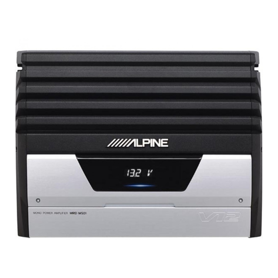
Summary of Contents for Alpine MRD-M501
-
Page 1: Service Manual
SERVICE MANUAL MONO POWER AMPLIFIER TO ALPINE Home Page 2 / 04-A 68E36267S01 MRD-M501... - Page 2 <Cautions for Safe Repair Work> The following cautions will prevent accidents in the workplace and will ensure safe products. *The symbols indicate caution is needed to prevent injuries and damage to property. The symbols and their meanings follow. If you ignore this symbol and handle the product incorrectly or unsafely, Warning serious injury or death may result.
-
Page 3: Table Of Contents
MRD-M501 Contents Packing Assembly Parts List Packing Method View Specifications Block Diagram Parts Layout on P.W.Boards and Wiring Diagram 7 , 8 Schematic Diagram 9 , 10 Terminal Voltage of IC/ TR 11 to 13 Description of IC Terminal Exploded View (Cabinet) NOTE : Due to continuing product improvement, specifications and designs are subject to change without notice. -
Page 4: Packing Assembly Parts List
MRD-M501 Packing Assembly Parts List Symbol Description Symbol Description Part No. Part No. 101-1 03E36238S01 SCR(M4X20 TPG1,BLK) 101-6 47E35195S01 WRENCH (4mmX4.6mm) 101-2 03E36208S01 WRENCH BOLT(M3X12(WHT)) #1 102-1 68P04190K32 OWNERS MANUAL(AE) 101-3 15E36257S01 COVER TERMINAL(B) $1 102-1 68P04190K18 OWNERS MANUAL(GE) 101-4 47E22594S01 WRENCH (2.5mmX2.9mm) -
Page 5: Specifications
MRD-M501 Specifications Power Output (20Hz, 100Hz) ................. 4ohm, 1% T.H.D., 14.4V : 260W 2ohm, 1% T.H.D., 14.4V : 500W T.H.D. (100Hz) ........................ 200W/ch/4ohm, 14.4V : 1% S/N Ratio (Ref. Output 275W/4ohm, Input short, Gain Position 0dB) ..............81dB Residual Noise (Input Short, Gain Position 0dB) ....................30mV Frequency Response (Ref. -
Page 6: Block Diagram
Block Diagram MRD-M501 JK101 INPUT BUFFER INPUT TML501 ISOLATOR Output LC Filter DIGITAL POWER MODE E-VOL AMPLIFIER L+Rch LC Filter PRE OUT JK101 Output Protection circuit DIN301 ANALOG +9V ANALOG +5V Over current Commander DIGITAL +5V low 2nd volt TET thermal... - Page 7 E203 C221 D103 1PS226 JK101 RCA,JACK 04P(ISOLATED) C204 E121 R156 Z101 3.3/50(B.P) ACM4532 TP143 R152 TP144 C106 TP111 1000p-CH TP124 C108 C109 R210 R111 0.01 0.01 R102 TP129 R153 TP126 TP108 R160 TP125 C149 R103 E112 R208 E122 0.01 3.3/50(B.P) R179 R201 D104...
- Page 8 TP230 R501 TP201 TP212 TP229 R901 C503 R507 C504 33-1/4 1000p-CH TP195 C901 R563 TP202 820p-CH 12-1/4 TP236 SD501 R564 E401 EP05H10 12-1/4 N.U. TP197 E509 C406 TP198 10/100 N.U. TP305 C902 820p-CH LG108 C405 R904 C549 1000p TP193 TP203 0.33/100 D501 TP194...
- Page 9 MRD-M501 Terminal Voltage of IC/TR IC101 IC102 4.1m 5.075 8.913 4.506 4.8m 4.9m 4.49 4.445 9.9m 4.502 4.503 4.481 -15.153 4.498 4.49 9.98m 4.503 4.49 4.495 9.8m 4.485 4.503 4.499 4.76m 4.444 4.889 8.975 15.204 4.504 4.503 5.077 IC103 IC104 IC107 13.46m...
- Page 10 MRD-M501 IC302 IC303 IC304 5.074 4.1m 5.077 5.078 4.1m 5.077 3.98m 4.06m 4.1m 4.1m 4.1m 5.078 5.078 4.05m 3.98 IC305 IC306 IC307 15.154 4.22m 2.925 3.62m 5.077 4.9m 2.925 3.69m 4.17m 4.9m 4.3m -15.209 3.3m 5.077 1.907 4.1m 5.077 5.077 1.251...
- Page 11 MRD-M501 IC601 IC602 IC603 5.078 14.318 14.326 3.92m 4.24m 4.12m 13.652 5.072 8.093 IC604 IC606 5.074 2.597 252.7m 8.018 2.594 247.1m 3.89m 4.025 14.328 198.2m 14.327 3.88m 1.693 5.039 3.752 5.039 3.87m 5.039 14.328 3.85m IC610 IC612 14.326 14.313 4.62m 4.25m...
-
Page 12: Description Of Ic Terminal
MRD-M501 Description of IC Terminal TMP86PM47U : IC301 Symbol Terminal Description GND connect terminal of A/D converter. Crystal OSC connect terminal. XOUT TEST TEST terminal. Power supply terminal. (4.5 to 5.5V) I2C_SDA I2C-SDA output terminal. I2C_SCL I2C-SCL output terminal. RESET RESET terminal. -
Page 13: Exploded View (Cabinet)
MRD-M501 Exploded View (Cabinet) TML501 DIN301 F601 TML101 F602 TO PARTS LIST TO CONTENTS - 15 -... -
Page 14: Electrical Parts List
MRD-M501 Electrical Parts List * Each parts on P.W.Board are described in order of the reference number. =======MAIN P.W.Board C104 08E33660S01 CAP, CER 102-J-CHIH C105 08E33660S01 CAP, CER 102-J-CHIH C106 08E33660S01 CAP, CER 102-J-CHIH C107 08E33660S01 CAP, CER 102-J-CHIH C108... - Page 15 MRD-M501 C220 08E31820S01 CAP,CER 104-K-B1E-CP C221 08E31820S01 CAP,CER 104-K-B1E-CP C222 08E31820S01 CAP,CER 104-K-B1E-CP C223 08E33110S01 CAP,CER 102-K-B1H-CP C300 08E31820S01 CAP,CER 104-K-B1E-CP C301 08E29517S01 CAP,TF,AMCS 682-J-RD C302 08E28771S01 CAP,CER 103-K-B1H-CP C303 08E28771S01 CAP,CER 103-K-B1H-CP C304 08E31170S01 CAP,CER 223-K-B1H-CP C305 08E28771S01 CAP,CER 103-K-B1H-CP...
- Page 16 MRD-M501 C529 08E25317S01 CAP,TF,MMTS 474-J-RD C530 08E33110S01 CAP,CER 102-K-B1H-CP C531 08E31820S01 CAP,CER 104-K-B1E-CP C532 08S55504Y01 CAP,CER 334 MX7R2A-CP C533 08E31820S01 CAP,CER 104-K-B1E-CP C535 08E33110S01 CAP,CER 102-K-B1H-CP C537 08E33110S01 CAP,CER 102-K-B1H-CP C539 08E33110S01 CAP,CER 102-K-B1H-CP C541 08E33110S01 CAP,CER 102-K-B1H-CP C543 08E33110S01...
- Page 17 MRD-M501 CL301 91T45281Y04 OSC,CER CSTCR7M70-E1 D103 48T85357W01 DIO,1PS226-CP D104 48T85357W01 DIO,1PS226-CP D105 48T85357W01 DIO,1PS226-CP D106 48T85357W01 DIO,1PS226-CP D301 48T15702W01 DIO,CP SB05-05CP D302 48T68828F11 DIO,1SS133-RH D303 48T15702W01 DIO,CP SB05-05CP D501 48E23841S01 DIO,DAP,202K-T-146-CP D601 48T84052F11 DIO SI 11ES2-TB5-R5 D602 48T75453Y01 DIO,RF2001T2D-DB D603...
- Page 18 MRD-M501 E605 23E36230S01 CAP,ELEC,47/25-M-RD E606 23E36230S01 CAP,ELEC,47/25-M-RD E607 23E36236S01 CAP,ELEC,SHL 330/25-M-RD E608 23E36254S01 CAP,ELEC 330/10-M-RD E614 23E36236S01 CAP,ELEC,SHL 330/25-M-RD E620 23E33401S01 CAP,ELEC,SHL 100/10-M-RD E623 23E33346S01 CAP,ELEC,SHL 100/16-M-RD E624 23E33346S01 CAP,ELEC,SHL 100/16-M-RD E625 23E36233S01 CAP,ELEC,470/25-M-RD E626 23E36233S01 CAP,ELEC,470/25-M-RD E627 23T75395Y01 CAP,KMH 822-1V +...
- Page 19 MRD-M501 Q505 48E36246S01 FET,SFP9Z34 PBF Q506 48E36246S01 FET,SFP9Z34 PBF Q507 48T75511Y01 FET, IRFZ34E Q508 48T75511Y01 FET, IRFZ34E Q601 48E23853S01 TR,2SB 1243Q-TV4-RD Q602 48E22095S01 TR, DTC 143XK-T-146-CP Q603 48E28010S01 TR,2SB 1238Q-TL4-RD Q605 48E22902S01 TR,2SC2412K-Q,R,S-T146-CP Q609 48T75459Y01 FET,IRF3205 PBF Q610 48T75459Y01 FET,IRF3205 PBF...
- Page 20 MRD-M501 R179 06E33329S01 RES,CF,511-J-1/16-CP R180 06E33329S01 RES,CF,511-J-1/16-CP R201 06E28533S01 RES,CF,102-J-1/16-CP R205 06E31685S01 RES,CF,105-J-1/16-CP R206 06E28533S01 RES,CF,102-J-1/16-CP R207 06E28533S01 RES,CF,102-J-1/16-CP R208 06E31160S01 RES,CF,473-J-1/16-CP R209 06E28624S01 RES,CF,0R0-J-1/16-CP R210 06E28624S01 RES,CF,0R0-J-1/16-CP R211 06E28548S01 RES,CF,471-J-1/16-CP R301 06E20752S01 RES,CF, 221-J-1/4-CP R302 06E31153S01 RES,CF,222-J-1/16-CP R303 06E28534S01...
- Page 21 MRD-M501 R380 06E20545S01 RES,CF, 33R-J-1/4-CP R381 06E20545S01 RES,CF, 33R-J-1/4-CP R382 06E20545S01 RES,CF, 33R-J-1/4-CP R383 06E28533S01 RES,CF,102-J-1/16-CP R384 06E28533S01 RES,CF,102-J-1/16-CP R401 06E31174S01 RES,CF,332-J-1/16-CP R402 06E32201S01 RES,CF,391-J-1/16-CP R403 06E31148S01 RES,CF,101-J-1/16-CP R404 06E28624S01 RES,CF,0R0-J-1/16-CP R501 06E31148S01 RES,CF,101-J-1/16-CP R506 06E33314S01 RES RW 0.01R-J-5W R507...
- Page 22 MRD-M501 R633 06E34813S01 RES,CF,303-F-1/16-CP R636 06E33392S01 RES,CF,821-J-1/16-CP R638 06E34536S01 RES,CF,242-F-1/16-CP R639 06E31175S01 RES,CF,822-J-1/16-CP R640 06E28535S01 RES,CF,223-J-1/16-CP R641 06E36252S01 RES,CF,302-F-1/16-CP R642 06E34813S01 RES,CF,303-F-1/16-CP R643 06E23597S01 RES,CF, 182-J-1/4-CP R644 06E23597S01 RES,CF, 182-J-1/4-CP R645 06E23597S01 RES,CF, 182-J-1/4-CP R646 06E31159S01 RES,CF,303-J-1/16-CP R647 06E28549S01 RES,CF,472-J-1/16-CP...
- Page 23 MRD-M501 Z101 91T75197Y01 EMI,ACM4532-801-E2 Z102 91T75197Y01 EMI,ACM4532-801-E2 Z201 91T65112W04 EMI,BK2125 HS601-CP Z208 91T15509Y08 EMI,BK1608HM102-CP Z301 91T15509Y08 EMI,BK1608HM102-CP Z302 91T15509Y08 EMI,BK1608HM102-CP Z303 91T15509Y08 EMI,BK1608HM102-CP Z304 91T15509Y08 EMI,BK1608HM102-CP Z305 91T65112W04 EMI,BK2125 HS601-CP Z306 91T65112W04 EMI,BK2125 HS601-CP Z307 91T15509Y08 EMI,BK1608HM102-CP Z308 91T15509Y08 EMI,BK1608HM102-CP...
- Page 24 MRD-M501 Cabinet Assembly Parts List Note : The part that has not PART NUMBER will not be supplied. - - - - - - - - - - - MAIN H/SINK - - - - - - - - - - -...
Need help?
Do you have a question about the MRD-M501 and is the answer not in the manual?
Questions and answers