ABB ret650 Commissioning Manual
Transformer protection
Hide thumbs
Also See for ret650:
- Technical manual (670 pages) ,
- Applications manual (392 pages) ,
- Commissioning manual (112 pages)
Table of Contents
Advertisement
Quick Links
Advertisement
Table of Contents

Related Manuals for ABB ret650


Summary of Contents for ABB ret650
- Page 1 ® Relion 650 series Transformer protection RET650 Commissioning Manual...
- Page 3 Document ID: 1MRK 504 126-UEN Issued: February 2011 Revision: - Product version: 1.1 © Copyright 2011 ABB. All rights reserved...
- Page 4 Copyright This document and parts thereof must not be reproduced or copied without written permission from ABB, and the contents thereof must not be imparted to a third party, nor used for any unauthorized purpose. The software or hardware described in this document is furnished under a license and may be used or disclosed only in accordance with the terms of such license.
- Page 5 (EMC Directive 2004/108/EC) and concerning electrical equipment for use within specified voltage limits (Low-voltage directive 2006/95/EC). This conformity is the result of tests conducted by ABB in accordance with the product standards EN 50263 and EN 60255-26 for the EMC directive, and with the product standards EN 60255-1 and EN 60255-27 for the low voltage directive.
- Page 6 In case any errors are detected, the reader is kindly requested to notify the manufacturer. Other than under explicit contractual commitments, in no event shall ABB be responsible or liable for any loss or damage resulting from the use of this manual or the application of the equipment.
- Page 7 Safety information Dangerous voltages can occur on the connectors, even though the auxiliary voltage has been disconnected. Non-observance can result in death, personal injury or substantial property damage. Only a competent electrician is allowed to carry out the electrical installation. National and local electrical safety regulations must always be followed.
-
Page 9: Table Of Contents
Table of contents Table of contents Section 1 Introduction...............7 This manual..................7 Intended audience................7 Product documentation...............8 Product documentation set............8 Document revision history.............9 Related documents................9 Symbols and conventions..............10 Safety indication symbols............10 Manual conventions..............11 Section 2 Available functions............13 Main protection functions..............13 Back-up protection functions............13 Control and monitoring functions............14 Designed to communicate..............16 Basic IED functions................17... - Page 10 Table of contents Section 5 Testing IED operation.............31 Preparing the IED to verify settings..........31 Activating test mode.................33 Preparing the connection to the test equipment.......33 Connecting test equipment to the IED..........34 Releasing the function to be tested..........35 Verifying analog primary and secondary measurement....35 Testing protection functionality............37 Section 6 Testing functionality............39 Testing disturbance report..............39...
- Page 11 Table of contents Completing the test..............49 Breaker failure protection CCRBRF..........49 Checking the phase current operate value, IP> .....50 Checking the residual (earth fault) current operate value IN> set below IP> ..............50 Checking the re-trip and back-up times........51 Verifying the re-trip mode............51 Verifying the back-up trip mode..........52 RetripMode = Contact .......53 Verifying the case...
- Page 12 Table of contents Testing control functions..............65 Voltage control................65 Secondary test...............67 Check the activation of the voltage control operation.....68 Check the normal voltage regulation function......69 Check the undervoltage block function........69 Check the upper and lower busbar voltage limit....69 Check the overcurrent block function........70 Automatic voltage control for tap changer, parallel control TR8ATCC..............70 Completing the test..............74...
- Page 13 Table of contents Changing and setting the password..........88 Identifying IED application problems...........88 Inspecting the wiring...............89 Section 9 Glossary.................93 Commissioning Manual...
-
Page 15: Section 1 Introduction
Section 1 1MRK 504 126-UEN - Introduction Section 1 Introduction This manual The commissioning manual contains instructions on how to commission the IED. The manual can also be used by system engineers and maintenance personnel for assistance during the testing phase. The manual provides procedures for checking of external circuitry and energizing the IED, parameter setting and configuration as well as verifying settings by secondary injection. -
Page 16: Product Documentation
Section 1 1MRK 504 126-UEN - Introduction Product documentation 1.3.1 Product documentation set Engineering manual Engineering manual Engineering manual Installation manual Installation manual Installation manual Commissioning manual Commissioning manual Commissioning manual Operation manual Operation manual Operation manual Service manual Service manual Service manual Application manual Application manual... -
Page 17: Document Revision History
Document revision history Document revision/date Product series version History -/February 2011 First release 1.3.3 Related documents Documents related to RET650 Identity number Application manual 1MRK 504 124-UEN Technical manual 1MRK 504 125-UEN Commissioning manual 1MRK 504 126-UEN Table continues on next page... -
Page 18: Symbols And Conventions
Section 1 1MRK 504 126-UEN - Introduction Documents related to RET650 Identity number Product Guide, configured 1MRK 504 127-BEN Type test certificate 1MRK 504 127-TEN 650 series manuals Identity number Communication protocol manual, DNP3 1MRK 511 241-UEN Communication protocol manual, IEC 61850... -
Page 19: Manual Conventions
Section 1 1MRK 504 126-UEN - Introduction equipment may result in degraded process performance leading to personal injury or death. Therefore, comply fully with all warning and caution notices. 1.4.2 Manual conventions Conventions used in IED manuals. A particular convention may not be used in this manual. -
Page 21: Section 2 Available Functions
Section 2 1MRK 504 126-UEN - Available functions Section 2 Available functions Note that not all functions included in the tables below have commissioning information available. Main protection functions IEC 61850/ ANSI Function description Transformer Function block name Differential protection T2WPDIF Transformer differential protection, two winding T3WPDIF... -
Page 22: Control And Monitoring Functions
Section 2 1MRK 504 126-UEN - Available functions IEC 61850/ ANSI Function description Transformer Function block name GUPPDUP Directional underpower protection GOPPDOP Directional overpower protection DNSPTOC Negative sequence based overcurrent function Voltage protection UV2PTUV Two step undervoltage protection OV2PTOV Two step overvoltage protection ROV2PTOV Two step residual overvoltage protection OEXPVPH... - Page 23 Section 2 1MRK 504 126-UEN - Available functions IEC 61850/Function ANSI Function description Transformer block name I103USRCMD Function commands user defined for IEC60870-5-103 I103GENCMD Function commands generic for IEC60870-5-103 I103POSCMD IED commands with position and select for IEC60870-5-103 Secondary system supervision TCSSCBR Breaker close/trip circuit monitoring Logic...
-
Page 24: Designed To Communicate
Section 2 1MRK 504 126-UEN - Available functions IEC 61850/Function ANSI Function description Transformer block name SPGGIO IEC 61850 generic communication I/O functions SP16GGIO IEC 61850 generic communication I/O functions 16 inputs MVGGIO IEC 61850 generic communication I/O functions MVEXP Measured value expander block SPVNZBAT Station battery supervision... -
Page 25: Basic Ied Functions
Section 2 1MRK 504 126-UEN - Available functions IEC 61850/Function block ANSI Function description Transformer name GOOSEVCTRRCV Voltage control receiving block for GOOSE ETHFRNT Ethernet configuration of front port, LAN1 port and ETHLAN1 gateway GATEWAY GOOSEDPRCV GOOSE function block to receive a double point value GOOSEINTRCV GOOSE function block to receive an integer value GOOSEMVRCV... -
Page 27: Section 3 Starting Up
Section 3 1MRK 504 126-UEN - Starting up Section 3 Starting up Factory and site acceptance testing Testing the proper IED operation is carried out at different occasions, for example: • Acceptance testing • Commissioning testing • Maintenance testing This manual describes the workflow and the steps to carry out the commissioning testing. -
Page 28: Checking The Power Supply
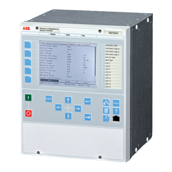
IED start-up sequence The following sequence is expected when the IED is energized. • The green Ready LED starts instantly flashing and the ABB logo is shown on the LCD. • After approximately 30 seconds, "Starting" is shown on the LCD. -
Page 29: Setting Up Communication Between Pcm600 And The Ied
Section 3 1MRK 504 126-UEN - Starting up If the green Ready LED continues to flash after startup, the IED has detected an internal error. Navigate via Main menu/Diagnostics/IED status/General to investigate the fault. Setting up communication between PCM600 and the IED The communication between the IED and PCM600 is independent of the used communication protocol within the substation or to the NCC. - Page 30 Section 3 1MRK 504 126-UEN - Starting up local HMI path Main menu/Configuration/Communication/TCP-IP configuration/1:ETHLAN1 and Rear OEM - port CD. The front and rear port IP addresses cannot belong to the same subnet or communication will fail. It is recommended to change the IP address of the front port, if the front and rear port are set to the same subnet.
- Page 31 Section 3 1MRK 504 126-UEN - Starting up IEC09000355-1-en.vsd IEC09000355 V1 EN Figure 3: Select: Network connections Select Properties in the status window. IEC09000356-1-en.vsd IEC09000356 V1 EN Figure 4: Right-click Local Area Connection and select Properties Select the TCP/IP protocol from the list of configured components using this connection and click Properties.
- Page 32 Section 3 1MRK 504 126-UEN - Starting up IEC09000357-1-en.vsd IEC09000357 V1 EN Figure 5: Select the TCP/IP protocol and open Properties Select Obtain an IP address automatically if the parameter DHCPServer is set to On in the IED. IEC09000358-1-en.vsd IEC09000358 V1 EN Figure 6: Select: Obtain an IP address automatically Select Use the following IP address and define IP address and Subnet mask if...
-
Page 33: Writing An Application Configuration To The Ied
Section 3 1MRK 504 126-UEN - Starting up IEC09000658-1-en.vsd IEC09000658 V1 EN Figure 7: Select: Use the following IP address Close all open windows and start PCM600. Setting up the PC to access the IED via a network This task depends on the used LAN/WAN network. PC and IED must belong to the same subnetwork. -
Page 34: Checking Ct Circuits
Section 3 1MRK 504 126-UEN - Starting up Be sure to set the correct technical key in the IED and PCM600 to prevent writing an application configuration to a wrong IED. See the engineering manual for information on how to create or modify an application configuration and how to write to the IED. -
Page 35: Checking The Rtxp Test Switch
Section 3 1MRK 504 126-UEN - Starting up Test the circuitry. • Polarity check • VT circuit voltage measurement (primary injection test) • Earthing check • Phase relationship • Insulation resistance check The polarity check verifies the integrity of circuits and the phase relationships. The check must be performed as close to the IED as possible. -
Page 36: Checking Binary Input And Output Circuits
Section 3 1MRK 504 126-UEN - Starting up Verify that the contacts are of voltage circuit type. Check that no short circuit jumpers are located in the slots dedicated for voltage. Trip and alarm circuits Check that the correct types of contacts are used. 3.10 Checking binary input and output circuits 3.10.1... -
Page 37: Section 4 Establishing Connection And Verifying The Iec 61850 Station Communication
Section 4 1MRK 504 126-UEN - Establishing connection and verifying the IEC 61850 station communication Section 4 Establishing connection and verifying the IEC 61850 station communication Setting the station communication To enable IEC 61850 station communication: • The IEC 61850-8-1 station communication functionality must be on in the local HMI. -
Page 39: Section 5 Testing Ied Operation
Section 5 1MRK 504 126-UEN - Testing IED operation Section 5 Testing IED operation Preparing the IED to verify settings If a test switch is included, start preparation by making the necessary connections to the test switch. This means connecting the test equipment according to a specific and designated IED terminal diagram. - Page 40 Section 5 1MRK 504 126-UEN - Testing IED operation Set and configure the function(s) before testing. Most functions are highly flexible and permit a choice of functional and tripping modes. The various modes are checked at the factory as part of the design verification. In certain cases, only modes with a high probability of coming into operation need to be checked when commissioned to verify the configuration and settings.
-
Page 41: Activating Test Mode
Section 5 1MRK 504 126-UEN - Testing IED operation Activating test mode Put the IED into the test mode before testing. The test mode blocks all functions in the IED, and the individual functions to be tested can be unblocked to prevent unwanted operation caused by other functions. -
Page 42: Connecting Test Equipment To The Ied
Section 5 1MRK 504 126-UEN - Testing IED operation winding open will cause a massive potential build up that may damage the transformer and injure humans. Connecting test equipment to the IED Connect the test equipment according to the IED specific connection diagram and the needed input and output signals for the function under test. -
Page 43: Releasing The Function To Be Tested
Section 5 1MRK 504 126-UEN - Testing IED operation Releasing the function to be tested Release or unblock the function to be tested. This is done to ensure that only the function or the chain of functions to be tested are in operation and that other functions are prevented from operating. - Page 44 Section 5 1MRK 504 126-UEN - Testing IED operation Apply input signals as needed according to the actual hardware and the application configuration made in PCM600. Inject a symmetrical three-phase voltage and current at rated value. Compare the injected value with the measured values. The voltage and current phasor menu in the local HMI is located under Main menu/Measurements/Analog primary values and Main menu/ Measurements/Analog secondary values.
-
Page 45: Testing Protection Functionality
Section 5 1MRK 504 126-UEN - Testing IED operation Also the Signal Monitoring tool in PCM600 can be used to read the measured values. In many cases it is more convenient to use PCM600 since, among many things, reports on measured values can be exported from the Signal Monitoring tool to other tools (for example, MS Excel) for further analysis. -
Page 47: Section 6 Testing Functionality
Section 6 1MRK 504 126-UEN - Testing functionality Section 6 Testing functionality Testing disturbance report 6.1.1 Introduction The following sub-functions are included in the disturbance report function: • Disturbance recorder • Event list • Event recorder • Trip value recorder •... -
Page 48: Testing Differential Protection Functions
Section 6 1MRK 504 126-UEN - Testing functionality Testing differential protection functions 6.3.1 Transformer differential protection T2WPDIF and T3WPDIF Prepare the IED for verification of settings as outlined in 5.1 "Preparing the IED to verify settings". Values of the logical signals for T2WPDIF are available on the local HMI under Main menu/Tests/Function status/Differential/T2WPDIF(87T,Id)/ 1:T2WPDIF. -
Page 49: Completing The Test
Section 6 1MRK 504 126-UEN - Testing functionality 12. If available on the test set a second harmonic current of about 20% (assumes 15% setting on I1/I2ratio parameter) can be added to the fundamental tone in phase L1. Increase the current in phase L1 above the start value measured in step 6. -
Page 50: Completing The Test
Section 6 1MRK 504 126-UEN - Testing functionality Connect the test set for single-phase current injection to the protection terminals connected to the CT in the power transformer neutral-to-earth circuit. Increase the injection current and note the operating value of the protection function. -
Page 51: Completing The Test
Section 6 1MRK 504 126-UEN - Testing functionality As the operating voltage is adjusted on the stabilizing resistor and with the setting of the resistor value in the function this is essential for the measurement of the expected value. Normally a slightly higher operating value is no problem as the sensitivity is not influenced much. -
Page 52: Testing Current Protection Functions
Section 6 1MRK 504 126-UEN - Testing functionality Testing current protection functions 6.4.1 Instantaneous phase overcurrent protection PHPIOC Prepare the IED for verification of settings as outlined in 5.1 "Preparing the IED to verify settings". Values of the logical signals for PHPIOC are available on the local HMI under Main menu/Tests/Function status/Current/PHPIOC(50,I>>)/1:PHPIOC. -
Page 53: Verifying The Settings
Section 6 1MRK 504 126-UEN - Testing functionality Values of the logical signals for OC4PTOC are available on the local HMI under Main menu/Tests/Function status/Current/OC4PTOC(51_67,4I>)/ 1:OC4PTOC. The Signal Monitoring in PCM600 shows the same signals that are available on the local HMI. 6.4.2.1 Verifying the settings Connect the test set for appropriate current injection to the appropriate IED... -
Page 54: Completing The Test
Section 6 1MRK 504 126-UEN - Testing functionality Check of the non-directional phase overcurrent function. This is done in principle as instructed above, without applying any polarizing voltage. 6.4.2.2 Completing the test Continue to test another function or end the testing by setting the parameter TestMode to Off under Main menu/Tests/IED test mode/1:TESTMODE. -
Page 55: Completing The Test
Section 6 1MRK 504 126-UEN - Testing functionality 6.4.3.2 Completing the test Continue to test another function or end the testing by setting the parameter TestMode to Off under Main menu/Tests/IED test mode/1:TESTMODE. If another function is tested, then set the parameter Blocked to No under Main menu/ Tests/Function test modes/Current/EFPIOC(50N,IN>>)/1:EFPIOC for the function, or for each individual function in a chain, to be tested next. -
Page 56: Four Step Non-Directional Residual Overcurrent Protection
Section 6 1MRK 504 126-UEN - Testing functionality 11. Check that the protection does not operate when the polarizing voltage is zero. 12. Repeat the above described tests for the higher set steps. 13. Finally, check that start and trip information is stored in the event menu. 6.4.4.2 Four step non-directional residual overcurrent protection Do as described in... -
Page 57: Completing The Test
Section 6 1MRK 504 126-UEN - Testing functionality Check in the same way as the operate and reset values of IBase1 for phases L2 and L3. Activate the digital input for cooling input signal to switch over to base current IBase2. Check for all three phases the operate and reset values for IBase2 in the same way as described above for stage IBase1 Deactivate the digital input signal for stage IBase2. -
Page 58: Checking The Phase Current Operate Value, Ip
Section 6 1MRK 504 126-UEN - Testing functionality Signal Monitoring in PCM600 shows the same signals that are available on the local HMI. The Breaker failure protection function CCRBRF should normally be tested in conjunction with some other function that provides a start signal. An external START signal can also be used. -
Page 59: Checking The Re-Trip And Back-Up Times
Section 6 1MRK 504 126-UEN - Testing functionality 6.4.6.3 Checking the re-trip and back-up times The check of the set times can be made in connection with the check of operate values above. Choose the applicable function and trip mode, such as FunctionMode = Current and setting RetripMode = No CBPos. -
Page 60: Verifying The Back-Up Trip Mode
Section 6 1MRK 504 126-UEN - Testing functionality Apply the fault condition, including start of CCRBRF, with current below set current value. Verify that re-trip is achieved after set time t1, but no back-up trip is obtained. Disconnect AC and START input signals. 6.4.6.5 Verifying the back-up trip mode In the cases below it is assumed that FunctionMode = Current is selected. -
Page 61: Verifying The Case Retripmode = Contact
Section 6 1MRK 504 126-UEN - Testing functionality may be arranged by feeding three- (or two-) phase currents with equal phase angle (I0-component) below IP>, but of such value that the residual (earth fault) current (3I ) will be above set value IN>. Verify that back-up trip is not achieved. -
Page 62: Completing The Test
Section 6 1MRK 504 126-UEN - Testing functionality Disconnect the AC and the START signal(s). Keep the CB closed signal(s). Apply the fault and the start again. The value of current should be below the set value I>BlkCont. Arrange disconnection of BC closed signal(s) well before set back-up trip time t2. -
Page 63: Completing The Test
Section 6 1MRK 504 126-UEN - Testing functionality 6.4.7.2 Completing the test Continue to test another function or end the testing by setting the parameter TestMode to Off under Main menu/Tests/IED test mode/1:TESTMODE. If another function is tested, then set the parameter Blocked to No under Main menu/ Tests/Function test modes/Current/CCRPLD(52PD)/X:CCRPLD for the function, or for each individual function in a chain, to be tested next. - Page 64 Section 6 1MRK 504 126-UEN - Testing functionality Table 2: Calculation modes Mode Set value: Formula used for complex power calculation L1, L2, L3 × × × (Equation 1) EQUATION1697 V1 EN Arone × × (Equation 2) EQUATION1698 V1 EN PosSeq = ×...
-
Page 65: Completing The Test
Section 6 1MRK 504 126-UEN - Testing functionality Increase the current to 100% of IBase. Switch the current off and measure the time for activation of TRIP1, trip of stage 1. If a second stage is used, repeat steps for the second stage. 6.4.8.2 Completing the test Continue to test another function or end the testing by setting the parameter... -
Page 66: Completing The Test
Section 6 1MRK 504 126-UEN - Testing functionality equal to 100% of rated power and that the reactive power is equal to 0% of rated power. Change the angle between the injected current and voltage to Angle1 + 90°. Check that the monitored active power is equal to 0% of rated power and that the reactive power is equal to 100% of rated power. -
Page 67: Completing The Test
Section 6 1MRK 504 126-UEN - Testing functionality Check that the START signal resets. Instantaneously decrease the voltage in one phase to a value about 20% lower than the measured operate value. Measure the time delay for the TRIP signal, and compare it with the set value. Extended testing The test above can now be repeated for step 2. -
Page 68: Completing The Test
Section 6 1MRK 504 126-UEN - Testing functionality 6.5.2.2 Completing the test Continue to test another function or end the testing by setting the parameter TestMode to Off under Main menu/Tests/IED test mode/1:TESTMODE. If another function is tested, then set the parameter Blocked to No under Main menu/ Tests/Function test modes/Voltage/OV2PTOV(59,2U>)/1:OV2PTOV for the function, or for each individual function in a chain, to be tested next. -
Page 69: Verifying The Settings
Section 6 1MRK 504 126-UEN - Testing functionality Values of the logical signals for OEXPVPH are available on the local HMI under Main menu/Tests/Function status/Voltage/OEXPVPH(24,U/f>)/1:OEXPVPH. The Signal Monitoring in PCM600 shows the same signals that are available on the local HMI. 6.5.4.1 Verifying the settings Enable function. -
Page 70: Verifying The Settings
Section 6 1MRK 504 126-UEN - Testing functionality Values of the logical signals for SAPTUF are available on the local HMI under Main menu/Tests/Function status/Frequency/SAPTUF(81,f<)/X:SAPTUF. The Signal Monitoring in PCM600 shows the same signals that are available on the local HMI. 6.6.1.1 Verifying the settings Verification of START value and time delay to operate... -
Page 71: Overfrequency Protection Saptof
Section 6 1MRK 504 126-UEN - Testing functionality Tests/Function test modes/Frequency/SAPTUF(81,f<)/X:SAPTUF for the function, or for each individual function in a chain, to be tested next. Remember to set the parameter Blocked to Yes, for each individual function that has been tested. 6.6.2 Overfrequency protection SAPTOF Prepare the IED for verification of settings as outlined in... -
Page 72: Completing The Test
Section 6 1MRK 504 126-UEN - Testing functionality Slowly increase the frequency of the applied voltage, to a value above StartFrequency. Check that the START signal does not appear. Wait for a time corresponding to tDelay, and make sure that the TRIP signal does not appear. -
Page 73: Completing The Test
Section 6 1MRK 504 126-UEN - Testing functionality The test above can be repeated to check a positive setting of StartFreqGrad. The tests above can be repeated to test the RESTORE signal, when the frequency recovers from a low value. 6.6.3.2 Completing the test Continue to test another function or end the testing by setting the parameter... - Page 74 Section 6 1MRK 504 126-UEN - Testing functionality Signal Monitoring in PCM600 shows the same signals that are available on the local HMI. Values of the logical signals for TR8ATCC are available on the local HMI under Main menu/Tests/Function status/Control/TR8ATCC(90)/X:TR8ATCC. The Signal Monitoring in PCM600 shows the same signals that are available on the local HMI.
-
Page 75: Secondary Test
Section 6 1MRK 504 126-UEN - Testing functionality • Tap change timeout duration - effectively the maximum transformer tap change time, tTCTimeout, available on the local HMI under Main menu/ Settings/IED Settings/Control/TCMYLTC (84)/1:TCMYLTC/ tTCTimeout. • Load tap changer pulse duration - required length of pulse from IED to load tap changer, tPulseDur, available on the local HMI under Main menu/Settings/IED Settings/Control/TCMYLTC (84)/1:TCMYLTC/ tPulseDur. -
Page 76: Check The Activation Of The Voltage Control Operation
Section 6 1MRK 504 126-UEN - Testing functionality represents the secondary transformer bus voltage UB adjusted for Load drop compensation (LDC) where enabled in settings. Note that when LDC is disabled, UB equals U When the load voltage U stays within the interval between U1 and U2, no action will be taken. -
Page 77: Check The Normal Voltage Regulation Function
Section 6 1MRK 504 126-UEN - Testing functionality 6.7.1.3 Check the normal voltage regulation function Review the settings for UDeadband (based on percentage of nominal bus voltage) and calculate the upper (U2) and lower (U1) voltage regulation limits for which a tap change command will be issued. Review the expected time for first (t1) and subsequent (t2) tap change commands from the voltage control function on the local HMI under Main menu/Settings/IED Settings/Control/TR8ATCC (90)/1:TR8ATCC/Time/... -
Page 78: Check The Overcurrent Block Function
Section 6 1MRK 504 126-UEN - Testing functionality General/UVPartBk and Main menu/Settings/IED Settings/Control/ TR8ATCC (90)/n:TR8ATCC/General/OVPartBk. Decrease the injected voltage slightly below the Umin value and check for the corresponding blocking or alarm condition on the local HMI. For an alarm condition, the voltage regulation function is not blocked and a raise command should be issued from the IED. - Page 79 Section 6 1MRK 504 126-UEN - Testing functionality The parameter corresponding to the own IED must not be set. T1RXOP should thus not be set in IED T1, T2RXOP not in IED T2, and so on. The lowest transformer number in the parallel group is by default set as the Master –...
- Page 80 Section 6 1MRK 504 126-UEN - Testing functionality • T1RXOP and T2RXOP shall be set to On in instance 3 of TR8ATCC, • T2RXOP and T3RXOP shall be set to On in instance 1 of TR8ATCC and so on. The parameter corresponding to the own IED must not be set. T1RXOP should thus not be set in IED T1, T2RXOPnot in IED T2 and so on.
- Page 81 Section 6 1MRK 504 126-UEN - Testing functionality > Udi U (Equation 12) EQUATION2092 V1 EN UB Uset (for the purposes of this test procedure) (Equation 13) EQUATION2094 V1 EN Therfore: × × > Ci Icc i Xi U Uset (Equation 14) EQUATION2096 V1 EN Uset...
-
Page 82: Completing The Test
Section 6 1MRK 504 126-UEN - Testing functionality Confirm that OperationPAR is set to CC for each transformer in the parallel group. Confirm that OperCCBlock is set to On for each transformer in the parallel group. Review the setting for CircCurrLimit. Review the setting for CircCurrBk to confirm whether a circulating current limit will result in an Alarm state, Auto Block or Auto&Man Block of the automatic voltage control for tap changer, for parallel control function... -
Page 83: Testing Logic Functions
Section 6 1MRK 504 126-UEN - Testing functionality Testing logic functions 6.8.1 Tripping logic SMPPTRC Prepare the IED for verification of settings as outlined in 5.1 "Preparing the IED to verify settings". Values of the logical signals for SMPPTRC are available on the local HMI under Main menu/Tests/Function status/Logic/SMPPTRC(94,1->0)/X:SMPPTRC. -
Page 84: Completing The Test
Section 6 1MRK 504 126-UEN - Testing functionality The output TRIP must be active and stay active after each fault, CLLKOUT must be set. Repeat. Reset the lockout. All functional outputs should reset. Deactivate the TRIP signal lockout function, set TripLockout = Off and the automatic lockout function, set AutoLock = Offif not needed. - Page 85 Section 6 1MRK 504 126-UEN - Testing functionality Navigate to the test mode folder. Change the On setting to Off. Press the 'E' key and the left arrow key. Answer YES, press the 'E' key and exit the menus. Commissioning Manual...
-
Page 87: Section 7 Commissioning And Maintenance Of The Fault Clearing System
AC or DC transients, high ambient temperatures, and high air humidity always have a certain likelihood of causing damages. Delivered equipment undergoes extensive testing and quality control in the ABB manufacturing program. All types of IEDs and their integral components have been subject to extensive laboratory testing during the development and design work. -
Page 88: Commissioning Tests
The periodicity of all tests depends on several factors, for example the importance of the installation, environment conditions, simple or complex equipment, static or electromechanical IEDs, and so on. The normal maintenance praxis of the user should be followed. However ABB proposal is to test: Every second to third year... -
Page 89: Visual Inspection
IED at a time on live circuits where redundant protection is installed and de-energization of the primary circuit is not allowed. ABB protection IEDs are preferably tested by aid of components from the COMBITEST testing system described in information B03-9510 E. Main... - Page 90 Section 7 1MRK 504 126-UEN - Commissioning and maintenance of the fault clearing system right order to allow for simple and safe secondary testing even with the object in service. Preparation Before starting maintenance testing, the test engineers should scrutinize applicable circuit diagrams and have the following documentation available: •...
- Page 91 Section 7 1MRK 504 126-UEN - Commissioning and maintenance of the fault clearing system Trip circuit check When the protection IED undergoes an operational check, a tripping pulse is normally obtained on one or more of the output contacts and preferably on the test switch.
- Page 92 Section 7 1MRK 504 126-UEN - Commissioning and maintenance of the fault clearing system to harmonics. Normally a CVT secondary can have around 2.5 - 3% third-harmonic voltage. Restoring Maintenance is very important to improve the availability of the protection system by detecting failures before the protection is required to operate.
-
Page 93: Section 8 Troubleshooting
Inspect the IED visually. • Inspect the IED visually to find any physical error causes. • If you can find some obvious physical damage, contact ABB for repair or replacement actions. Check whether the error is external or internal. •... -
Page 94: Checking The Communication Link Operation
Section 8 1MRK 504 126-UEN - Troubleshooting 8.1.3.1 Checking the communication link operation There are several different communication links on the product. First check that all communication ports that are used for communication are turned on. Check the front communication port RJ-45. 1.1. -
Page 95: Indication Messages
Section 8 1MRK 504 126-UEN - Troubleshooting Indication messages 8.2.1 Internal faults When the Ready LED indicates an internal fault by flashing, the message associated with the fault is found in the internal event list in the LHMI menu Main menu/Diagnostics/Internal events. -
Page 96: Additional Indications
Section 8 1MRK 504 126-UEN - Troubleshooting internal fault signals can also be checked via the LHMI in Main menu/Diagnostics/ IED status/General. When a fault appears, record the fault indication message and state it when ordering service. Table 4: Warning indications Warning indication Additional information Warning... -
Page 97: Inspecting The Wiring
Section 8 1MRK 504 126-UEN - Troubleshooting • Check that the function is on. • Check that the correct setting group (1 to 4) is activated. • Check the blocking. • Check the mode. • Check the measurement value. • Check the connection to trip and disturbance recorder functions. - Page 98 Section 8 1MRK 504 126-UEN - Troubleshooting GUID-BBAEAF55-8D01-4711-A71D-BBC76B60BA3D V1 EN Figure 9: Testing output contacts using the voltage drop method 1 Contact current 2 Contact voltage drop 3 Load 4 Supply voltage Commissioning Manual...
- Page 99 Section 8 1MRK 504 126-UEN - Troubleshooting GUID-31DF5495-91F1-4A4B-8FD5-50625038961E V1 EN Figure 10: Testing a trip contact 1 Trip contact under test 2 Current limiting resistor • To check the status of the output circuits driving the output relay via the LHMI, select Main menu/Tests/Binary output values/Binary output modules and then navigate to the board with the actual binary output to be checked.
- Page 100 Section 8 1MRK 504 126-UEN - Troubleshooting navigating to the actual I/O-board and the binary input in question. The activated output signal is indicated with a yellow-lit diode. Each BOn_PO is represented by two signals. The first signal in LHMI is the actual value 1 or 0 of the output, and in PCM600 a lit or dimmed diode.
-
Page 101: Section 9 Glossary
Section 9 1MRK 504 126-UEN - Glossary Section 9 Glossary Alternating current Application configuration tool within PCM600 A/D converter Analog-to-digital converter ADBS Amplitude deadband supervision Analog input ANSI American National Standards Institute Autoreclosing ASCT Auxiliary summation current transformer Adaptive signal detection American Wire Gauge standard Binary input Binary outputs status... - Page 102 Section 9 1MRK 504 126-UEN - Glossary Central processor unit Carrier receive Cyclic redundancy check CROB Control relay output block Carrier send Current transformer Capacitive voltage transformer Delayed autoreclosing DARPA Defense Advanced Research Projects Agency (The US developer of the TCP/IP protocol etc.) DBDL Dead bus dead line DBLL...
- Page 103 Section 9 1MRK 504 126-UEN - Glossary FOX 20 Modular 20 channel telecommunication system for speech, data and protection signals FOX 512/515 Access multiplexer FOX 6Plus Compact time-division multiplexer for the transmission of up to seven duplex channels of digital data over optical fibers G.703 Electrical and functional description for digital lines used by local telephone companies.
- Page 104 Section 9 1MRK 504 126-UEN - Glossary I-GIS Intelligent gas-insulated switchgear Instance When several occurrences of the same function are available in the IED, they are referred to as instances of that function. One instance of a function is identical to another of the same kind but has a different number in the IED user interfaces.
- Page 105 Section 9 1MRK 504 126-UEN - Glossary apparent impedance to the fault applied to the balance point, that is, the set reach. The relay “sees” the fault but perhaps it should not have seen it. Peripheral component interconnect, a local data bus Pulse code modulation PCM600 Protection and control IED manager...
- Page 106 Section 9 1MRK 504 126-UEN - Glossary SMA connector Subminiature version A, A threaded connector with constant impedance. Signal matrix tool within PCM600 Station monitoring system SNTP Simple network time protocol – is used to synchronize computer clocks on local area networks. This reduces the requirement to have accurate hardware clocks in every embedded system in a network.
- Page 107 Section 9 1MRK 504 126-UEN - Glossary dissemination of standard frequencies and time signals. UTC is derived from International Atomic Time (TAI) by the addition of a whole number of "leap seconds" to synchronize it with Universal Time 1 (UT1), thus allowing for the eccentricity of the Earth's orbit, the rotational axis tilt (23.5 degrees), but still showing the Earth's irregular rotation, on which UT1 is based.
- Page 110 Contact us ABB AB Substation Automation Products SE-721 59 Västerås, Sweden Phone +46 (0) 21 32 50 00 +46 (0) 21 14 69 18 www.abb.com/substationautomation...