Advertisement
EUROSTER 1100E – USER MANUAL
Congratulations on choosing our thermostatic controller EUROSTER. It is a technically
advanced product which will serve you and your family for years bringing energy savings and
thermal comfort.
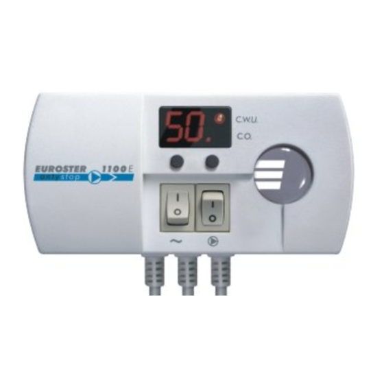
1. Status indication – DHW mode
2. Status indication – heating mode
3. Temperature adjustment – up
4. Mode switch: DHW/ heating, temperature adjustment – down
5. On/off switch for continuous pump operation
6. On/off mains switch
7. Temperature sensor
8. Pump supply, 230 V AC
9. Controller supply, 230 V AC
10. Pump status
1. INSTALLATION
DANGER!!! Dangerous voltage is present both inside the enclosure and on the
outgoing cables. Prior to installation by a qualified electrician make sure that
the unit has been disconnected from power supply to avoid the risk of electric
shock. Units with mechanical damage should not be installed.
a. mounting of the controller:
•
the controller is fixed directly to the wall or to any other support with two screws
(plastic plugs c/w screws are part of delivery)
•
the cables extending from the controller are fixed to the wall with cable clips
b. mounting of the temperature sensor:
•
the sensor is NOT intended for immersion in liquids and installation on
breechings (flues between the boiler and chimney)
•
install the heating water temperature sensor on the bare outlet pipe of the boiler (as
close to the boiler as possible) or on the hot water cylinder
•
secure the sensor on the pipe by tightening the supplied fixing clip
NOTE: As a recommendation, the outlet pipe should be provided with thermal insulation on
the section between the boiler and the temperature sensor. If the central heating system is
supplied from both a coal- and a gas-fired boiler, the temperature sensor should be installed at
the meeting point of the two outlet pipes and insulated.
c. connecting of the power supply cable to the pump:
•
connect the yellow or yellow/green wire (protective conductor) to terminal (
•
connect the blue wire to terminal (N)
EUROSTER 1100E
1
)
Advertisement
Table of Contents

Related Manuals for EUROSTER 1100E


Summary of Contents for EUROSTER 1100E
- Page 1 EUROSTER 1100E – USER MANUAL EUROSTER 1100E Congratulations on choosing our thermostatic controller EUROSTER. It is a technically advanced product which will serve you and your family for years bringing energy savings and thermal comfort. 1. Status indication – DHW mode 2.
- Page 2 EUROSTER 1100E – USER MANUAL • connect the brown wire to terminal (L) d. check-up of connections: • make sure the connections have been made as indicated and secure the cover of the pump motor terminal box e. connection of the controller: •...
- Page 3 With the () switch in position I in DHW mode the pump will be switched off at 90°C and restarted when the temperature has dropped below 90°C. 4. COMPLIANCE WITH STANDARDS AND CONFORMITY CERTIFICATES EUROSTER 1100 E is in compliance with the following EU directives: EMC, LVD The CE certificate of conformity is posted on our website: www.euroster.com.pl 5.
- Page 4 7. WIRING DIAGRAMS These are simplified diagrams and as such they not show all the components necessary for fully functional operation of the system. wiring of EUROSTER 1100E in a system with a stand-alone hot water cylinder heating boiler hot water cylinder...
- Page 5 - radiator temperature sensor EUROSTER 1100E wiring between EUROSTER 1100E and an integral hot water cylinder heating boiler hot water cylinder shutoff valve strainer heating water circulating pump check valve...
Need help?
Do you have a question about the 1100E and is the answer not in the manual?
Questions and answers