Table of Contents
Advertisement
INSTRUCTION MANUAL
21-inch Single Stage Gas Snow Thrower
Model # DB7005
Have product questions or need technical support? Please feel free to contact us!
Website: www.Amerisuninc.com
www.powersmartusa.com
Toll free: USA (800)791-9458 Mon-Fri 9-5 EST
Canada (888)980-4937 Mon-Fri 9-5 EST
Email:
support@amerisuninc.com
Advertisement
Table of Contents

Related Manuals for Powersmart DB7005


Summary of Contents for Powersmart DB7005
-
Page 1: Instruction Manual
INSTRUCTION MANUAL 21-inch Single Stage Gas Snow Thrower Model # DB7005 Have product questions or need technical support? Please feel free to contact us! Website: www.Amerisuninc.com www.powersmartusa.com Toll free: USA (800)791-9458 Mon-Fri 9-5 EST Canada (888)980-4937 Mon-Fri 9-5 EST Email:... -
Page 3: Table Of Contents
Storage & Cleaning…………...…………………………………………. Troubleshooting…………………………………………………………. Exploded view and parts list……………………………………………... 20 Two (2) years limited warranty……………………...…………………… 24 TECHNICAL DATA 21-inch Single Stage Gas Snow Thrower Model #: DB7005 Engine: 196cc Snow Engine Engine oil Capacity: 20 fl.oz Fuel Tank Capacity: 0.42 Gallon... -
Page 4: Introduction
INTRODUCTION ® Thank You for Purchasing a PowerSmart Product. This manual provides information regarding the safe operation and maintenance of this product. Every effort has been made to ensure the accuracy of the ® information in this manual. PowerSmart reserves the right to change this product and specifications at any time without prior notice. - Page 5 TRAINING Read, understand, and follow all instructions on the machine and in the manual(s) before attempting to assemble and operate. Keep this manual in a safe place for future and regular reference. • Be familiar with all controls and their proper operation. Know how to stop the machine and disengage them quickly.
- Page 6 • Read, understand and follow all instructions on your Snow Thrower and in this Operator's Manual before attempting to assemble and operate your machine. • Keep this manual in a safe place for future and regular reference. If replacement parts are needed, refer to the manual.
- Page 7 • Never store the machine or fuel container inside where there is an open flame, spark or pilot light (e.g. furnace, water heats, space heater, clothes dryer etc.). • Allow machine to cool at least 5 minutes before storing. • Never fill containers inside a vehicle or on a truck or trailer bed with a plastic liner.
- Page 8 • Disengage power to the auger impeller when transporting or not in use. • Never operate machine at high transport speeds on slippery surfaces. Look down and behind and use care when backing up. • If the machine should start to vibrate abnormally, stop the engine, disconnect the spark plug wire and ground it against the engine.
- Page 9 • Check control levels periodically to verify they engage and disengage properly and adjust, if necessary. Refer to the adjustment section in this operator's manual for instructions. • Maintain or replace safety and instruction labels, as necessary. • Observe proper disposal laws and regulations for gas, oil, etc. to protect the environment. •...
-
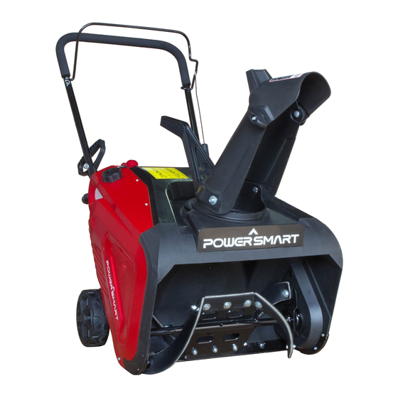
Page 10: Knowing Your Snow Thrower
KNOWING YOUR SNOW THROWER Use the illustrations below to become familiar with the locations and functions of the various components and controls of this snow thrower. Auger Control Bar Wheel Chute Rotation Handle Fuel Tank Discharge Chute Fuel Tank Cap Shave Plate Recoil Starter handle Auger... - Page 11 Oil Dipstick Switch Key Choke lever Primer Bulb Drain Plug Auger Control Bar The Auger Control Bar is used to engage and disengage the augers. Pull back the Auger Control Bar to engage the augers; release to disengage the augers. Chute Rotation Handle To adjust snow discharge direction, rotate the handle clockwise or counter-clockwise.
-
Page 12: Assembly And Adjustments
ASSEMBLY AND ADJUSTMENTS The following section describes steps necessary to prepare the snow thrower for use. If after reading this section, you are unsure about how to perform any of the steps please call USA (800) 791-9458 or Canada (888)980-4937 Mon-Fri 9-5 EST for customer service. Failure to perform these steps properly can damage the snow thrower or shorten its life. - Page 13 2. Insert the bolts into the aligned holes, with the bolt heads on the inside of the handle. 3. Install the washers and knobs on the bolts on the outside of the handle. Tighten firmly by hand. NOTICE: Do not bend or kink the control cable. The cables should be routed under the Lower handle and not wrapped around the handle or knobs.
-
Page 14: Snow Thrower Preparation
SNOW THROWER PREPARATION Step 1 - ADD OIL The snow thrower is shipped without oil. User must add the proper amount of oil before operating the snow blower for the first time. The oil capacity of the engine crankcase is 20 fl. oz. For general use, we recommend 5W, 4-stroke engine oil. -
Page 15: Operating Your Snow Thrower
OPERATING YOUR SNOW THROWER The following section describes steps to use your Snow Thrower for use. If after reading this section, you are unsure about how to perform any of the steps please call 1-800-791-9458 for customer service. Failure to perform these steps properly can damage your Snow Thrower or shorten its life. Review the SAFETY section in this manual before operating the engine and snow thrower. -
Page 16: Clearing Snow
STARTING 1. Move the choke lever to START position (Right side). 2. Press the primer bulb 3 times. 3. Insert switch key into slot (Do not turn switch key). 4. Pull on the recoil starter handle slowly until a slight resistance is felt, then pull quickly to start the engine. -
Page 17: Maintenance
MAINTENANCE WARNING! Never perform maintenance while your Snow Thrower is running. Turn OFF the engine before performing any maintenance tasks on your Snow Thrower. Proper maintenance of your Snow Thrower will help prolong its life. Please perform the following maintenance procedures as required. Do not attempt to repair your Snow Thrower unless you have the proper tools and instructions for disassembly and repair. -
Page 18: Storage & Cleaning
CHANGING/ADDING OIL Change the oil according to the Recommended Maintenance Schedule. Change the oil when the engine is warm. This will allow for complete drainage. Change oil more often if operating under heavy load. It is also necessary to drain the oil from the crankcase if it has become contaminated with water or dirt. The oil capacity of the engine is 20 fl.oz. -
Page 19: Troubleshooting
TROUBLESHOOTING Problem Causes Remedy WARNING - Before attempting to make any inspections, repairs or adjustments, stop the engine, wait for all moving parts to stop moving and carefully disconnect the engine spark plug wire. If tipping or turning the snow blower is required for any inspection or repair, first wait until the engine is cool to the touch and then drain the engine of all fuel and oil into suitable containers and store or dispose of in a proper manner. -
Page 20: Exploded View And Parts List
EXPLODED VIEW AND PARTS LIST... - Page 21 Item Stock# Description Item Stock# Description 303020106 Hex washer screw M10x1 203050171 Chute base 303042013 flat washer 10 303190253 Engine 302110079 Small rubber blade 303200098 shock absorb 303030036 Lock nut 303020275 Hex washer screw 302110078 Rubber blade 303060099A Small belt pulley 303180852 Auger axle 303020279...
- Page 22 Engine exploded view and parts list...
- Page 23 Item Stock # Description Item Stock # Description 380140215-0003 Bolt M6x14 380740696-0001 Breather tube 120220031-0001 Cylinder head cover 130150039-0001 Connecting rod 120250013-0001 Head cover gasket 380560056-0001 Pin ring 380140336-0001 Bolt M8x60 130070079-0001 Piston ring combination 120080276-0001 Cylinder head 130030083-0001 Piston 380140089-0003 Bolt M6x8 130060031-0001...
-
Page 24: Two (2) Years Limited Warranty
Limited Warranty, you must return the entire power tool product; transportation prepaid, to PowerSmart Include a legible copy of the original receipt, which lists the date of purchase (month and year) and the name of the company purchased from.
Need help?
Do you have a question about the DB7005 and is the answer not in the manual?
Questions and answers
how do i adjust the valves on my power smart snow blower