Table of Contents
Advertisement
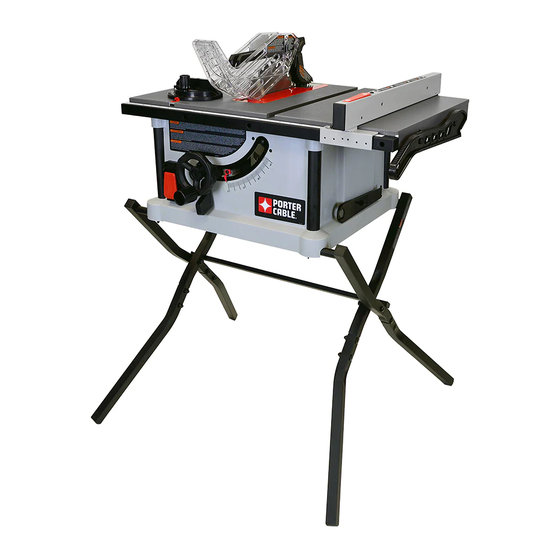
10-IN PORTABLE TABLE SAW
Français (#)
Español (#)
www.portercable.com
Instruction Manual
To reduce the risk of serious injury, thoroughly read and comply with all warnings and instructions in this manual and on product.
KEEP THIS MANUAL NEAR YOUR SAW FOR EASY REFERENCE AND TO INSTRUCT OTHERS
PCX362010
Advertisement
Table of Contents

Related Manuals for Porter-Cable PCX362010


Summary of Contents for Porter-Cable PCX362010
- Page 1 Español (#) www.portercable.com Instruction Manual PCX362010 To reduce the risk of serious injury, thoroughly read and comply with all warnings and instructions in this manual and on product. KEEP THIS MANUAL NEAR YOUR SAW FOR EASY REFERENCE AND TO INSTRUCT OTHERS...
-
Page 2: Table Of Contents
TURNING THE SAW ON AND OFF ........18 SPANISH ..................# MAKING CUTS ................ 19 FUNCTIONAL DESCRIPTION SPECIFICATIONS The PORTER CABLE PCX362010 10-inch Max depth of cut at 90 degrees: 3” Portable Table Saw is designed for high quality Max depth of cut at 45 degrees: 2-1/2”... -
Page 3: Safety Symbol-Definitions
SAFETY SYMBOLS- DEFINITIONS The definitions below describe the level of severity of each signal word. Please read the manual and pay attention to these symbols. Indicates an imminently hazardous situation which, if not avoided, will result in death or serious injury. Indicates a potentially hazardous situation which, if not avoided, could result in death or serious injury. -
Page 4: Proposition 65 Warning
GENERAL POWER TOOL SAFETY RULES (CONTINUED) and heavy enough to carry the current your product keys and wrenches are removed before starting will draw. An undersized cord will cause a drop tool. in line voltage, resulting in loss of power and 24. -
Page 5: Table Saw Safety Rules
TABLE SAW SAFETY RULES TERMINOLOGY The following terms will be used throughout the manual and you should become familiar with them. — Through-cut - any cut that completely cuts through — Freehand - cutting without the use of a miter the workpiece. -
Page 6: Saw Blade Guard, Anti-Kickback Pawls And Riving Knife Assembly
TABLE SAW SAFETY RULES fixtures or feather boards to help guide and control WORKPIECE AGAINST THE BLADE to reduce The workpiece. Accessories for use with your saw the risk of a thrown workpiece. are available at extra cost from your local dealer or 21. -
Page 7: Kickbacks
TABLE SAW SAFETY RULES (CONTINUED) KICKBACKS Kickbacks can cause serious injury. A kickback occurs the nearest authorized service center for repair. when a part of the workpiece binds between the saw • Plastic and composite materials (like hardboard) blade and the rip fence, or other fixed object, and rises may be cut on your saw. -
Page 8: Power Connections
POWER CONNECTIONS POWER SOURCE This saw is equipped with a 15-amp motor for use with A separate electrical circuit should be used for your a 120-volt, 60-HZ alternating current. See instructions machines. This circuit should not be less than #12 wire below regarding proper connections for your saw. -
Page 9: Shipping Contents
UNPACKING (CONTINUED) SHIPPING CONTENTS A. Saw Stand Part 2 B. Rip Fence J. Stand legs (4) C. Blade K. Blade Wrenches (on board storage) D. Anti-Kickback Pawls L. Push Stick E. Blade Guard M. Extension Wing Throat Plate N. Fence Rail G. -
Page 10: Contents Of Hardware Bag
UNPACKING (CONTINUED) CONTENTS OF HARDWARE BAG Description (QTY) g. M5 x 10 mm (3/8 in.) Hex Socket Cap Screw (3) a. M8 x 35 mm (1 1/2 in.) Carriage Bolt (8) h. M5 Flat Washer (2) b. M8 Lock Nut (8) M5 x 25 mm (1 in.) Hex Socket Cap Screw (6) c. -
Page 11: General Parts Knowledge
GENERAL PARTS KNOWLEDGE RIVING KNIFE ANTI-KICKBACK PAWLS BLADE GUARD THROAT PLATE TABLE FENCE LOCK MITER GAUGE RIP FENCE SCALE EXTENSION WING FENCE RAIL PUSH STICK HEIGHT ADJUSTMENT WHEEL HEX/PHILLIPS WRENCH BEVEL SCALE ON/OFF SWITCH BLADE WRENCHES BEVEL LOCK STAND ASSEMBLY The part and hardware names and letters correspond to those used in General Parts Knowledge on Page 11 and the Shipping Contents on page 9 &... - Page 12 ASSEMBLY (CONTINUED) NOTE: Please refer to (Fig. 2) for correct stand cross section parts setup. CORRECT INCORRECT FIG. 2 With assembled cross section stand open, attach legs (J) to the stand using (8) M8 x 35mm (1 1/2 in.) carriage bolts (a) and (8) M8 lock nuts (b).
-
Page 13: Attaching Saw To Stand
ASSEMBLY (CONTINUED) ATTACHING STAND TO SAW Place saw (A) on stand assembly while aligning wing screws with threaded holes in saw base. See Fig. 6 and Tighten wing screws to secure stand assembly to saw (A). NOTE: Do not over tighten. STAND ASSEMBLY FIG. -
Page 14: Height Adjustment Knob Installation
ASSEMBLY (CONTINUED) Insert (2) remaining M5 x 25mm (1 in.) hex socket cap screws (i) through the fence rail (N) and extension wing (M) and secure with (2) M5 kep nuts (k) as shown in Fig. 10. Use straightedge to ensure extension wing is level as shown in Fig. -
Page 15: Position The Riving Knife
ASSEMBLY (CONTINUED) POSITION THE RIVING KNIFE A riving knife is a flat plate that fits into the cut made by the saw blade (the “kerf”). It is intended to reduce the risk of kickback by holding the kerf open and lessening the tendency of the workpiece to pinch the blade. -
Page 16: Anti-Kickback Pawls And Blade Guard
ASSEMBLY (CONTINUED) If adjustment is needed, remove the throat plate and adjust the (4) Phillips set screws (Fig. 16a) up or down as needed. See Fig. 16. Replace throat plate and recheck. Repeat this process as needed until the throat plate is level. -
Page 17: Rip Fence
ASSEMBLY (CONTINUED) RIP FENCE Position rip fence (B) over the table as shown in Fig. 19. Lower rip fence (B) over front of rail on the front of the saw and back of the table as shown in Fig. 19a. Engage lock on the rip fence after placing fence in desired location on the table. -
Page 18: Operation
OPERATION Failure to comply with the following warnings may result in serious personal injury. READ ENTIRE MANUAL. In addition to reading these operating instructions, it is important to read and understand the entire manual before operating this saw. Follow all applicable instructions regarding assembly, preparation, and adjustment prior to making any cuts and comply with all safety rules and warnings in this section and elsewhere throughout this manual. -
Page 19: Making Cuts
MAKING CUTS Failure to comply with the following warnings may result in serious personal injury. • Never touch the free end of the workpiece or a free alignment and clearance with saw blade. Check piece that is cut off, while the power is on and/or alignment after each change of beveling angle. -
Page 20: Rip Cuts
MAKING CUTS (CONTINUED) RIP CUTS 1. Remove miter gauge 13. Do not push or hold onto the free or cut-off side of the workpiece. 2. Make sure bevel angle is set to 0°. 14. Continue pushing the workpiece until it is clear of 3. -
Page 21: Crosscutting
MAKING CUTS (CONTINUED) CROSSCUTTING 7. Make sure the workpiece is clear of the blade - at least 1 inch or 25mm away - before starting the • NEVER use the fence as a guide or length stop saw. when crosscutting. 8. -
Page 22: Compound Miter Cuts
MAKING CUTS (CONTINUED) COMPOUND MITER CUTS This is a combination of bevel crosscutting and mitering. Refer to Figure 26 and follow the instructions for both bevel crosscutting and mitering. Remember to use the right miter slot on the right side of the blade for all bevel cuts. -
Page 23: Cutting Aids And Accessories
CUTTING AIDS AND ACCESSORIES PUSH STICK In order to operate your table saw safely, you must use a push stick whenever the size or shape of the workpiece would otherwise cause your hands to be within 6-inches (152mm) of the saw blade or other cutter. -
Page 24: Auxiliary Miter Gauge Facing
CUTTING AIDS AND ACCESSORIES (CONTINUED) AUXILIARY MITER GAUGE FACING An auxiliary miter gauge facing is used to increase the surface area of the miter gauge face. If desired, you can fit the miter gauge with an auxiliary wood facing that should be at least 1-inch (25mm) higher than the maximum depth of cut, and at least as wide as the miter gauge. -
Page 25: Featherboard
CUTTING AIDS AND ACCESSORIES (CONTINUED) FEATHERBOARD Featherboards are used to keep the workpiece in 1. Select a solid piece of lumber approximately contact with the fence and table (Figure 30), and help ¾-inch thick, 2 ½-inches wide and 12-inches long. prevent kickback. -
Page 26: Making Adjustments
MAKING ADJUSTMENTS LEVELING THE THROAT PLATE Check that the throat plate is properly adjusted to the table. Front of throat plate should be level or slightly below the surface of the table and rear of the throat plate should be level or slightly above the surface of the table. See Fig. 15. There are four phillips set screws (A) pre-assembled to the table that are used to level the throat plate. -
Page 27: Adjusting The Blade Height
MAKING ADJUSTMENTS (CONTINUED) ADJUSTING THE BLADE HEIGHT ADJUSTMENT For all through cuts, the top of the blade points should WHEEL be above the workpiece and the bottom of the blade gullets are below the top surface of workpiece. For non-through cuts, the top of the blade points should be set to the depth of the cut. - Page 28 RIVING KNIFE ALIGNMENT Your riving knife may be out of alignment if your work NON-THRU CUT piece is hitting the riving knife after the cut or causing POSITION some binding during the cut. When this condition occurs you will need to make an adjustment to the THRU-CUT riving knife alignment.
-
Page 29: Maintenance
MAINTENANCE To reduce the risk of injury, turn unit off and disconnect it from power source before cleaning or servicing, before installing and removing accessories, before adjusting and when making repairs. An accidental start-up can cause injury. KEEP MACHINE CLEAN Periodically blow out all air passages with dry compressed air. -
Page 30: Warranty
® PORTER-CABLE will either repair or replace this product, without charge, if it has any defects due to faulty materials or workmanship for three years from the date of purchase. This warranty does not cover part failure due to normal wear or tool abuse, products purchased in used or damaged condition or from a retailer located outside the United States or Canada. - Page 31 NOTES...
- Page 32 2651 New Cut Rd. Spartanburg, SC 29303 1-844-816-8986 www.portercable.com Copyright © 2016 PORTER CABLE DPEC004198 - 02-01-16 Rev Date: 02-03-16...
Need help?
Do you have a question about the PCX362010 and is the answer not in the manual?
Questions and answers