Table of Contents
Advertisement
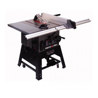
10 IN. (254 MM) STATIONARY TABLE SAW
BANC DE SCIE 254 MM (10 PO)
SIERRA DE MESA 254 MM (10 PULG.)
Instruction Manual
Manuel d'instructions
Manual de instrucciones
www.portercable.com
INSTRUCTIVO DE OPERACIÓN, CENTROS
DE SERVICIO Y PÓLIZA DE GARANTÍA.
ADVERTENCIA: LÉASE ESTE
CATALOG NUMBER
INSTRUCTIVO ANTES DE USAR EL
PCB270TS
PRODUCTO.
– 1 –
Advertisement
Table of Contents

Related Manuals for Porter-Cable PCB270TS


Summary of Contents for Porter-Cable PCB270TS
- Page 1 10 IN. (254 MM) STATIONARY TABLE SAW BANC DE SCIE 254 MM (10 PO) SIERRA DE MESA 254 MM (10 PULG.) Instruction Manual Manuel d’instructions Manual de instrucciones www.portercable.com INSTRUCTIVO DE OPERACIÓN, CENTROS DE SERVICIO Y PÓLIZA DE GARANTÍA. ADVERTENCIA: LÉASE ESTE...
-
Page 2: Table Of Contents
To avoid electrical hazards, fire hazards or damage to the table saw, use proper circuit protection. This table saw is wired at the factory for 110-120/220-240 Volt operation. It must be connected to a 110-120 Volt / 15 Ampere or 220-240 Volt / 7.5 Ampere time delay fuse or circuit breaker. -
Page 3: Safety Guidelines - Definitions
SAFETY GUIDELINES - DEFINITIONS WARNING ICONS Your power tool and its Instruction Manual may contain “WARNING ICONS” (a picture symbol intended to alert you to, and/or instruct you how to avoid, a potentially hazardous condition). Understanding and heeding these symbols will help you operate your tool better and safer. Shown below are some of the symbols you may see. SAFETY ALERT: Precautions that involve your safety. -
Page 4: Power Tool Safety
25. Dust generated from certain materials can be hazardous to your health. Always operate saw in well-ventilated area and provide for proper dust removal. -
Page 5: Table Saw Safety
KICKBACK AND FINGER/HAND AMPUTATIONS. 5. NEVER STAND or have any part of your body in line with the path of the saw blade. Keep your hands out of the saw blade path. 6. NEVER REACH behind or over the cutting tool for any reason. - Page 6 How to Avoid Them and Protect Yourself from Possible Injury: a. Be certain that the rip fence is parallel to the saw blade. b. Do not rip by applying the feed force to the section of the workpiece that will become the cut-off (free) piece.
-
Page 7: Electrical Requirements And Safety
To avoid electrical hazards, fire hazards, or damage to the tool, use proper circuit protection. Use a seperate electrical circuit for your tool. Your saw is wired at the factory for 120 V operation. Connect to a 120 V, 15 Amp circuit and use a 15 Amp time delay fuse or circuit breaker. -
Page 8: Tools Needed For Assembly
240 VOLT SINGLE PHASE OPERATION WARNING To avoid injury, disconnect the motor from power source outlet before reconnecting the wire. The motor supplied with your machine is a dual voltage, 120/240 volt motor. It is shipped ready-to-run for 120 volt operation. -
Page 9: Unpacking And Checking Contents
UNPACKING AND CHECKING CONTENTS Carefully unpack the table saw and all its parts, and compare against the list below and the illustration on the next page. With the help of an assistant place the saw on a secure surface and examine it carefully. - Page 10 UNPACKING YOUR TABLE SAW – 10 –...
-
Page 11: Know Your Table Saw
KNOW YOUR TABLE SAW Rip fence Table extension (left) Micro-adjustment rollers Blade elevation handwheel ON/OFF switch with key Power cord storage Rip fence storage Caster Front rail Rear rail Blade wrench & push stick storage Blade guard storage Anti-kickback pawl storage... -
Page 12: Glossary Of Terms
Always use a push block for rip widths less than 2 in (50.8 mm). RESAWING - flipping material to make a cut the saw is not capable of making in one pass. -
Page 13: Assembly And Adjustments
ASSEMBLY AND ADJUSTMENTS Estimated Assembly Time: 90~120 minutes (2 people) WARNING For your safety, never connect plug to power source receptacle until all assembly and adjustment steps are complete, and you have read and understood the safety instructions. ASSEMBLING STAND (FIG. A~I) 1. - Page 14 ASSEMBLING TABLE SAW TO STAND (FIG. J) 1. Lift the saw body (1) and place on the stand (2), 2. Bag “P” - Attach the table saw to the stand with four 3. Tighten all mounting bolts with a wrench.
- Page 15 BLADE GUARD ASSEMBLY STORAGE (FIG. K) Storage brackets for anti-kickback pawl and blade guard assembly are located on the right side of the saw base. 1. Bag “J, K” - Insert the bracket (1) into the left slot (2) on the right side of saw base, attach the brackets by using two of six screws (22).
- Page 16 Power cord storage (Fig. R) Storage for the power cord (3) is located on the left side of the stand. Wrap the power cord onto the brackets (4) when saw in not in use. This can prevent damage to the cord. Fig. R ASSEMBLING THE TABLE EXTENSION (FIG.
-
Page 17: Hex Nuts
ADJUSTING THE 90° AND 45° POSITIVE STOPS (FIG. X, Y, Z) Your saw has positive stops that will quickly position the saw blade at 90° and 45° to the table. Make adjustments necessary. – 17 – machine while spinning the blade until the latch locks into place and the blade will no longer turn. - Page 18 90° Stop (Fig. X, Y) 1. Disconnect the saw from the power source. 2. Turn the blade tilting handwheel until the blade tilting scale is at 90°. 3. Turn the blade elevation handwheel and raise the blade (1) to the maximum elevation.
-
Page 19: Aligning Riving Knife To Blade
Check alingment after each change of bevel angle. NOTE: DO NOT operate saw if riving knife is not locked in the thru-cut or non thru-cut position hole. Fig. DD ALIGNING THE RIVING KNIFE TO BLADE (FIG. -
Page 20: Installing Blade Guard Assembly
The maximum radial distance between the riving • knife and the toothed rim of the saw blade is 0.12 in ~ 0.31 in. (3 mm ~ 8 mm) The tip of the riving knife shall not be lower than 0.04 •... -
Page 21: Installing/Adjusting The Rip Fence
1. Lift upward on the rip fence handle (1) so the rear holding clamp (2) is fully extended. 2. Place the rip fence on the saw table and engage the holding clamp to the rear rail (3). Lower the front end into the front rail (4). -
Page 22: Nuts
RIP FENCE INDICATOR AJUSTMENT(FIG. KK) NOTE: The rip fence indicator points to the scale on the front of the table saw. Measurement shown by the indicator will provide the user with accuracy up to 1/16 in. (1.6 mm). Measurement shown is the distance from the blade to the side of the fence closest to the blade. -
Page 23: Basic Saw Operations
1. Lift the switch cover (1). 2. To turn the table saw ON, insert the black key (2) into the key slot in the center of the switch (3). 3. Push the key firmly into the slot, then pull switch up to the ON position to start the table saw. - Page 24 4. Place the workpiece flat on the table and against the fence. Keep the workpiece away from the blade. 5. Turn the saw ON and wait for the blade to come to full speed. 6. Slowly feed the workpiece into the blade by pushing forward only on the workpiece section (1) that will pass between the blade and the fence.
- Page 25 Move the workpiece to 1in. (25.4 mm) distance from the blade (3). 5. Start the saw and wait for the blade to come up to full speed. Never stand directly inline of the saw blade path, always stand to the side of the blade that you are cutting on.
- Page 26 BEVEL CROSSCUTTING (FIG. TT) This cutting operation is the same as crosscutting except the blade is at bevel angle other than 0°. WARNING Always work to the right side of the blade during this type of cut. The miter gauge (1) must be in the right side groove (4) because the bevel angle may cause the blade guard to interfere with the cut if used on the left side groove.
- Page 27 Blade or chipper must not exceed 13/16 inch (20.6 mm). 7. Check saw to ensure that the dado will not strike the housing, insert, or motor when in operation. WARNING...
- Page 28 Fig. ZZ 120 V Wire Wiring (Terminal Block) Blue Rocker Switch Black Black Black 120V 60HZ Power Brown White White Green Motor (GROUND) White White Black Terminal Block Black Blue Black Rocker Switch White Black Power Cord Green (GROUND) Motor Black White (Rocker Switch)
-
Page 29: Maintaining Your Table Saw
1. Clean out all sawdust that has accumulated inside the saw cabinet and the motor. 2. Polish the saw table with an automotive wax to keep it clean and to make it easier to slide the workpiece. 3. Clean cutting blades with pitch and gum remover. -
Page 30: Troubleshooting Guide
Use only identical replacement parts. For a parts list or to order parts, visit our service website at www.portercable. com. You can also order parts from your nearest Porter-Cable Factory Service Center or Porter-Cable Authorized Warranty Service Center. Or, you can call our Customer Care Center at (888) 609-9779. -
Page 31: Accessories And Attachments
Since accessories, other than those offered by Porter- Cable, have not been tested with this product, use of such accessories with this tool could be hazardous. To reduce the risk of injury, only Porter-Cable recommended accessories should be used with this product. -
Page 32: Push Stick Pattern
PUSH STICK PATTERN PUSH STICK CONSTRUCTION • Use good quality plywood or solid wood • Use 1/2 in. (13 mm) or 3/4 in. (19 mm) material • Push stick MUST be thinner than the width of material being cut Drill Hole for Hanging Notch for Prevent Hand from Slipping... -
Page 33: Square Nuts
10 IN. (254 MM) STATIONARY TABLE SAW PARTS LIST FOR TABLE SAW I.D. Description 2389 WHEEL 2390 COMPRESSION SPRING 2552 HANDLE 09JK WRENCH 0B98 BEVEL GEAR 0BAC SET NUT 0BAE ARBOR COLLAR 0GCM BEVEL GEAR 0HVX BALL BEARING 0J3V WRENCH HEX. - Page 34 10 IN. (254 MM) TABLE SAW SCHEMATIC FOR TABLE SAW ���� ���� ���� ���� � ���� ���� � � ���� ���� � ���� ���� ���� ���� ���� ���� ���� ���� ���� ���� ���� � ���� ���� � ���� � ����...
- Page 35 10 IN. (254 MM) STATIONARY TABLE SAW PARTS LIST & SCHEMATIC FOR STAND I.D. Description 01AE LEVELING PAD 0CSE POWER CORD CLAMP 0K7D CR. RE. ROUND WASHER HD. SCREW 0K7F CR. RE. ROUND WASHER HD. SCREW 0K7L CR. RE. ROUND WASHER HD. SCREW 0KJ7 CAP HD.
- Page 36 10 IN. (254 MM) STATIONARY TABLE SAW PARTS LIST & SCHEMATIC FOR MOTOR I.D. Description 1314 CR. RE. PAN HD. SCREW 1451 LEAD WIRE ASS’Y 0HVW BALL BEARING 0HVX BALL BEARING 0JAF EXTERNAL TOOTH LOCK WASHER 0JBA WAVE WASHER 0KF2 CR.-RE.
- Page 37 NOTES – 37 –...
-
Page 38: Warranty
In addition to the warranty, PORTER-CABLE tools are covered by our: 1 YEAR FREE SERVICE: PORTER-CABLE will maintain the tool and replace worn parts caused by normal use, for free, any time during the first year after purchase.
Need help?
Do you have a question about the PCB270TS and is the answer not in the manual?
Questions and answers