Shure DDS 5900 User Manual
Discussion system
Hide thumbs
Also See for DDS 5900:
- Manual (97 pages) ,
- User manual (81 pages) ,
- Upgrade manual (10 pages)

Related Manuals for Shure DDS 5900


Summary of Contents for Shure DDS 5900
-
Page 1: User Guide
Discussion and Conferencing DDS 5900 Discussion System USER GUIDE © 2016 Shure Incorporated 27A20456 (Rev. 1) -
Page 2: Important
Important Important Important Safeguards 1. Read these instructions - All the safety and operating 12. Do not defeat the safety purpose of the polarized or ground-type plug. A polarized plug has two blades with instructions should be read before the apparatus or system is operated. -
Page 3: Power Disconnect
Important Note for Power Connections 19. Safety Check - Upon completion of any service or repairs to this apparatus, ask the service technician to Check that the voltage of your local power supply is within perform safety checks to determine that the apparatus is the operating voltage of the unit. -
Page 4: Compliance
(screened) cable types may degrade EMC performance. more of the following measures: Changes or modifications not expressly approved by Shure • Reorient or relocate the receiving antenna. Incorporated could void your authority to operate this •... -
Page 5: Table Of Contents
Managing Speakers from the Web Browser Warranty Language Interpretation Certifications Troubleshooting Table of Contents Factory Default Reset Diagnostic Report DDS 5900 Digital Discussion System Firmware Update Features System Concepts External Control Protocol Component Overview General Protocol Behavior Central Control Unit... -
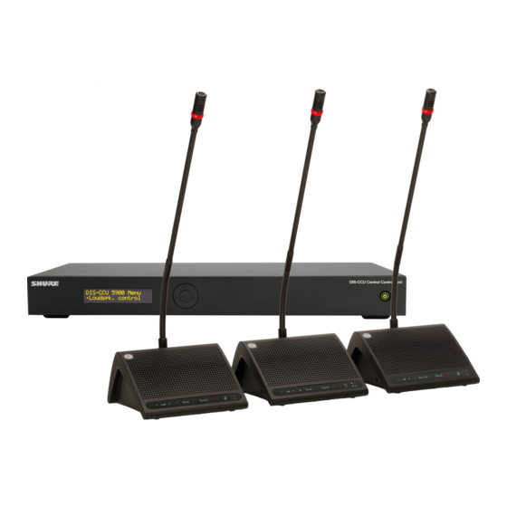
Page 6: Dds 5900 Digital Discussion System
Flexible Setup and Easy Installation The DDS 5900 system uses a proprietary protocol to transport digital audio, control data, and power over the same cable (shielded Cat5e). The system supports large events of up to 250 participants, easily scaling with additional components added inline for a simplified layout topology. -
Page 7: System Concepts
When a participant speaks, their voice is heard at the other units' loudspeakers. The DDS 5900 is a perfect solution when every participant is both a talker and a listener. -
Page 8: Component Overview
① DIS-CCU Central Control Unit The central control unit (CCU) is the processor for the DDS 5900 system. It provides power and control to the discussion units, analog audio inputs and outputs for external equipment, and a web server that hosts the browser interface for remote system control. -
Page 9: Central Control Unit
Central Control Unit The DIS-CCU Central Unit provides the intelligence for systems of up to 250 participants in the DDS 5900 system. It processes audio and control signals from each discussion and interpreter unit, and distributes audio to other participants for listening to the discussion. -
Page 10: Front Panel
Component Overview DIS-CCU Hardware Description DIS-CCU Central Control Unit TCP/IP Out A Out B Out C Out D Out E Out F Out G Out H DIS-CCU Central Unit Front Panel ⑦ Audio Outputs Eight balanced, male XLR connectors for connection to ①... - Page 11 Component Overview Simplified Audio Diagram DIS-CCU Audio Diagram...
-
Page 12: Menu Navigation
Component Overview Menu Navigation Main Menu The DIS-CCU provides controls from the front panel for system setup and configuration. Use the 5-button keypad to Loudspk. Control navigate the menu and change settings. Loudspk. Volume 0 to -40 dB, Off The figure below gives an overview of the menu structure. Mic ->... -
Page 13: Discussion Units
The sleek, professional design and minimal cabling allows seamless integration into professional meeting spaces. A DDS 5900 system supports up to 250 discussion units at the same time. - Page 14 Component Overview Model Variations DC 5980 P Portable Discussion Unit Sits on the tabletop without drilling or cutting the surface, and easily dismantles for system reconfiguration. Features include an integrated speaker, rear-exit cable routing, and operation as an chairman, delegate, or interpreter unit. DC 5980 P Portable Discussion Unit Integrated Design The following features are integrated in the unit...
- Page 15 • FP 5921 F: not supported Sound Reinforcement Add the optional LS 5900 F loudspeaker for listening to other talkers. Microphone Variations In addition to DIS microphones, several Shure Microflex Gooseneck microphones are compatible with the flushmount Ⓡ unit by connecting the AC 5901 adapter.
- Page 16 Component Overview Overlay Control Buttons The discussion unit is programmable to support different people involved in the discussion. For example, as the moderator of the discussion, the chairman has an extra control that immediately turns off all delegate microphones. DC 5900 F DC 5980 P Delegate (Participant) Chairman (Moderator)
- Page 17 Component Overview Overlay Variations DC 5980 P Portable Unit ▪ Delegates Buttons Image • speech • mute • Interpretation monitoring • headphone volume • speech • Interpretation monitoring • headphone volume ▪ Chairman Buttons Image • speech • delegate off •...
- Page 18 Component Overview DC 5900 F Flushmount Unit The DC 5900 F flushmount unit has two options for the front plate: ▪ FP 5981 F Front Plate (with interpretation monitoring) Delegates Buttons Image • speech • mute • interpretation monitoring • headphone volume •...
-
Page 19: Gooseneck Microphones
Component Overview Gooseneck Microphones GM 592x Series The DIS GM 592x microphone delivers excellent audio performance with a frequency response specifically tailored for speech. The gooseneck is on the base of the microphone, providing flexible positioning. A red LED ring at the top of the microphone clearly indicates when the microphone is active and the participant is speaking. - Page 20 Component Overview MX 400 Gooseneck for Flushmount Units The DC 5900 F Flushmount discussion unit functions with Shure MX 400 RLP series microphones. Featuring legendary Shure audio performance and build quality, CommShield Technology eliminates noise caused by ® smart phones, tablets, WiFi and other RFI. A red LED ring at the top of the microphone clearly indicates when the microphone is active and the participant is speaking.
-
Page 21: Additional Compatible Equipment
Component Overview Additional Compatible Equipment RC 6000 Redundancy Controller The following units are available to use in the DDS 5900 system: Enables the connection of a redundant PS-CCU power supply to protect the CCU operation against power failures. Additional Power and Advanced Setup... -
Page 22: Hardware Installation
The Shure EC for stable system performance. If an installation does 6001 are high-quality Ethernet cables available various not use Shure EC 6001 cables, they must follow the lengths from 0.5 m to 100 m. Each cable has been Cat5e cable requirements. -
Page 23: Connecting Microphone Units And Dcs-Lan Components
Hardware Installation Connecting Microphone Units and DCS-LAN Components Microphone units and DCS-LAN components are connected in sequence (daisy-chain) using the two RJ45 ports on each unit. The connectors are interchangeable; simply connect the previous unit to one port, and the following unit to the other port. -
Page 24: Connection Diagrams
Hardware Installation Connection Diagrams The following system diagrams illustrate typical hardware connections to the DIS-CCU central control unit. Actual installations may use different combinations of hardware, but follow the general concepts outlined below. Note: Flushmount and portable discussion units are interchangeable in the following drawings, unless noted. Basic Setup with Discussion Units The system is operational without the use of a computer. - Page 25 Wireless Control Interpretation Units The DDS 5900 Discussion System supports bilingual discussion, routing an interpretation channel to each discussion unit. Program the DC 5980 P portable discussion unit for use as an interpretation station. Other participants use the headphone jack on their unit to listen to the interpretation channel of their choice.
- Page 26 Connect a mixer to the CCU analog outputs to control individual microphone volume or equalization. Use the browser interface to buss units to groups and assign them to the specific output (A-H). To return the audio to the DDS 5900 system: 1. Connect the output of the external device to Audio Input 1 on the CCU 2.
-
Page 27: Wireless Language Distribution
Hardware Installation Wireless Language Distribution For additional monitoring, connect a wireless language distribution system to one of the CCU audio outputs. Use the browser interface to select the desired microphones (seat) for that group output (A-H). The DCS 6000 Digital Infrared Language System transmits this audio signal to a number of listening stations. -
Page 28: Power Requirements
Hardware Installation Power Requirements For most installations, the DIS-CCU supplies sufficient power for the discussion units. Depending on the setup, the CCU powers up to 50 units at a time without additional equipment. The number of supported discussion units depends on the size and layout of the installation. - Page 29 Hardware Installation Discussion Units Powered by the DIS-CCU The following tables show how to connect the most discussion units without adding additional equipment. Note: When using multiple chains, distribute the number of units evenly across the chains to maximize unit count. 1 m Spacing Between Discussion Units Estimated Number of Discussion Units Powered from CCU Cable length from...
- Page 30 Hardware Installation Using Junction Boxes The JB 6104 junction box adds four additional outputs to a point on the DCS-LAN chain. These four outputs are available for short-run connections to DUs, protecting the DCS-LAN chain from technical failures or hot-plugging damage. A single DU can connect to each JB output, with a maximum cable length of 10 m.
-
Page 31: Installing Large Systems
Hardware Installation Installing Large Systems Power Supplies for Additional Components To add additional components to the system, add an inline or rackmount power supply to the discussion unit chain. Inline Power Supply Use the PI-6000 power inserter to add an inline power supply for approximately 50 more discussion units. The unit may be connected at any point in the chain to power the additional components. - Page 32 Hardware Installation Extending Total Cable Length The CCU operates a system with up to 120 m of shielded Cat5e cable. To add more cable for large or more complex installations, add an RP 6004 Repeater before 120 m limit has been reached. The RP 6004 connects anywhere in the DCS-LAN chain, refreshing audio and control data for the units that follow it.
-
Page 33: Installing The Dc 5900 F
Hardware Installation Installing the DC 5900 F Installing the Base The DC 5900 base installs directly onto a table or podium. 1. Determine the location of the microphone and cut a hole with a diameter of 53 mm. 2. Use the base to mark the location for the screw and drill the holes. 3. - Page 34 Hardware Installation Installing the Loudspeaker 1. Determine the location of the speaker (<1m from the base to accommodate the cable) and cut a hole with a 53 mm diameter. 2. Insert the loudspeaker into the hole and connect the loudspeaker cable to the base unit. Make sure the cable is not pinched.
- Page 35 Hardware Installation Attaching the Front Plate 1. Align the front plate and place it onto the base. 2. Secure the plate to the base using the screws. 3. Snap the cover onto the front plate. cover front plate base Attaching the Front Plate Removal To remove the front plate: 1.
- Page 36 Hardware Installation...
-
Page 37: Installation Best Practices
Hardware Installation Installation Best Practices Follow these guidelines for the most reliable installation. Continuity of Shielding Shielding must be consistent through the DCS-LAN chain. Any cable or patch panel used for DIS components requires shielded RJ45 connectors. All DIS components feature shielded RJ45 female connectors. Avoiding Accidental Grounding (Galvanic Isolation) Avoid accidentally grounding the DCS-LAN signal with the chassis ground of a patch panel. - Page 38 Hardware Installation Bending Rule Do not sharply bend the cable. Ethernet cables cannot bend more than four-times the diameter of the cable. Pinching Do not over-fasten the cable. A pinched cable may not operate correctly.
-
Page 39: Using The Discussion Units
To lock the microphone into place, use the supplied hex key and turn counterclockwise. DIS GM: Simply insert the microphone into the XLR socket. Adjust the gooseneck for proper position. Shure MX4xxRLP: Attach the AC 5901 XLR/Microflex adapter to the microphone. Insert the adapter into the XLR socket of the flushmount unit. -
Page 40: Program The User Type
Program the User Type DDS 5900 discussion units are programmable, changing the function of the control buttons to support different user types. The three types are chairman, delegate, or interpreter, each requiring unique control functionality. The setting is stored in the unit, and persists after a power cycle. -
Page 41: Controlling The Discussion Unit
Using the Discussion Units Controlling the Discussion Unit Interpreter DDS 5900 discussion units are programmable during setup The primary function of the interpreter unit is to translate to support the role of each member of a meeting. the discussion into a foreign language. Participants that... -
Page 42: System Set Up
Note: The computer network is separate from the component network (DCS-LAN). System and Discussion Setup DDS 5900 Web Interface System Requirements For best performance, always update the browser to the latest released version. The following browsers function properly with the system interface: •... - Page 43 System Set Up Open the DIS-CCU System Interface Follow these instructions to open the browser interface on a computer. TCP/IP Connect to the CCU 1. Connect the computer to the port on the CCU. TCP/IP 2. Power on the equipment. 3.
- Page 44 System Set Up Assigning the Network Address Access to the system interface is available from two network addresses: IP address and hostname. Typing either address into a browser will access the interface of the connected CU. Manage the network address from the browser: >...
- Page 45 System Set Up Language Setting The browser interface is supported in a variety of languages. Go to > to select the desired language. System Language Albanian Shqip Arabic ةيبرعلا ةغللا Bosnian Bosanski Bulgarian български Chinese (Simplified) 中文(简体) Chinese (Traditional) 中文(繁體) Croatian Hrvatski Danish...
- Page 46 System Set Up Additional Interface Pages for Meeting Participants In addition to the administrator access to the web interface, there are two separate addresses useful to the participants during the meeting: • Microphone control for speaker management • Display-only page for meeting participants to view the speaker lists Display for participants Microphone control for the chairman By default, anyone can access these views from a computer or mobile device connected to the network.
- Page 47 System Set Up Microphone Control Page This page is dedicated for microphone control during the meeting. Use this view as a chairperson or meeting operator to manage speakers, speak requests, and replies. For access, enter the IP address of the CCU, followed by (example: /chairman http://172.17.11.137/chairman...
- Page 48 System Set Up Display Page The display page is used to provide the meeting participants with a view of the speaker, speak request, and reply lists. For access, enter the IP address of the CCU, followed by (example: /display http://172.17.11.137/display Tip: Put the page in full-screen mode during the meeting: •...
-
Page 49: Security
System Set Up Security DIS components use a proprietary codec algorithm to prevent unauthorized devices from listening to the audio signal. To further protect the discussion, assign a password to the browser interface and enable security features on wireless routers. Password Protect the Browser Interface You can assign a password to restrict access to the browser interface. - Page 50 System Set Up Removing the Password To clear the password access to the CCU, restore factory default settings. Note: Resetting to factory defaults will erase all delegate, system, and IP settings. From the Hardware a) Go to the front panel of the CCU. b) Scroll the main menu to Restore Factory Defaults c) Press the center button to enter menu d) Press the center button again to confirm the reset.
-
Page 51: Assigning Names And Seat Numbers
System Set Up Assigning Names and Seat Numbers When the discussion begins, the chairman or discussion moderator will need to refer to the participants by either name, seat number, or both. The proper assignment of names and seat numbers is critical to ensure the continuity of the discussion. - Page 52 System Set Up Add Participant names...
-
Page 53: Audio Settings
System Set Up Audio Settings The Floor Mix When a microphone is turned on, the audio is routed to the main mix (Group A) by default. This mix is often referred to as the floor mix because it transmits the audio from anyone participating in the meeting. Interpreters also listen to the floor to provide language interpretation for multilingual discussions. - Page 54 System Set Up Floor Mix on the Loudspeakers Loudspeakers are included in most microphone units for localized sound-reinforcement of the discussion. When a participant uses their microphone, their speech is heard at other unit loudspeakers. This improves speech clarity in large rooms and reduces typical problems associated with sound reinforcement systems.
- Page 55 System Set Up Headphone Channels Most microphone units include a headphone output for listening to interpreter channels or other participants on the floor channel. Each participant chooses their channel from the microphone unit channel selectors. Channels 1 and 2 are dedicated for language interpretation. Participants select one of the channels to listen to their language during a bilingual event.
- Page 56 System Set Up Audio Source for the Loudspeaker and Headphones By default all microphones are routed to loudspeaker and headphone mixes. To change the audio source: 1. Route microphones to to add them to the floor mix (all selected by default) >...
- Page 57 System Set Up Analog Audio Outputs Eight analog outputs are available for recording, language distribution system, teleconferencing unit, or an external PA system. TCP/IP DIS-CCU Out A Out B Out C Out D Out E Out F Out G Out H Eight Analog Outputs Go to >...
- Page 58 System Set Up 4. Select the routing for the audio channel: • Loudspeaker: to all microphone unit loudspeakers • Ch. 0: to the headphone output on the microphone unit 5. If desired, route the channel to Output A (Group) to output a blend of the external source with the microphone units: •...
- Page 59 System Set Up Emergency Audio Signal To prepare for an emergency, connect an Emergency Evacuation Message (EEM) audio signal to Input 2. The block connector provides a 'normally-open' switch that when closed, distributes the emergency signal to the loudspeakers and all input and output connections.
-
Page 60: Running A Discussion
Running a Discussion Running a Discussion Microphone Operation Modes FIFO (First In, First Out) The operation mode determines how participant microphones function during a meeting. Several factors Automatically turns on the participant microphone if there may affect the meeting requirements and the manner is room in the speaker list. - Page 61 Running a Discussion Speak Interrupt Mode This mode determines the behavior of the microphone units when the speaker list is full: • Off (default): A participant unit cannot turn on until a space is available in the speaker list. • On: A participant can turn on the microphone even when the speaker list is full. This turns off the microphone of the participant that has been in the list the longest (at the bottom of the Speaker List).
-
Page 62: Maximum Speaker Setting
Running a Discussion Maximum Speaker Setting To improve speaker management and clarity of the audio, there is a limit to the number of speakers at the same time. Up to eight chairman and delegate microphones can be open at once. There are several settings: Note: Interpreter units are always active and do not impact the speaker list. - Page 63 Running a Discussion Example Settings Chairman (Moderator) Can Speak At Any Time Set the total number of speakers to one (1) higher than the maximum number of participants. If there are two chairmen, set the number to two (2) higher. Using FIFO Mode First In, First Out (FIFO) mode automatically turns on microphones based on a chronological queue list.
-
Page 64: Voice Detection
Running a Discussion Voice Detection Voice Activation (VOX) In VOX mode, the microphone activates automatically once a participant speaks. The mode is ideal for meetings that are more conversational, allowing back-and-forth communication that doesn't involve speak requests and button activation. The following settings allow VOX to be customized for the meeting: Voice Detection Threshold Determines the input level (dB) that activates the microphone. - Page 65 Running a Discussion Auto Off This setting automatically turns off the microphone when the participant stops talking. • Off (default) • On Automatic Off Time The time for a microphone to turn off after the participant stops speaking. Default 20 seconds Minimum 5 seconds Maximum 60 seconds...
-
Page 66: Managing Speakers From The Web Browser
Running a Discussion Managing Speakers from the Web Browser For increased control over the meeting, the chairman uses the browser interface to activate microphones. The chairman page is dedicated for controlling the speaker list and request queue. The chairman can manually turn on/off microphones, or simply monitor the list in an automatic mode. - Page 67 Running a Discussion Open the Chairman Page For access to the chairman page, enter the IP address of the CCU, followed by (example: /chairman http://172.17.11.137/ chairman Controlling Participant Microphones The following buttons are available to the chairman for controlling the microphones during a meeting: Speak Instantly turns on a participant’s microphone.
-
Page 68: Language Interpretation
Running a Discussion Language Interpretation There are two additional audio channels used for language interpretation. In bilingual meetings, participants speak their native language into the microphone and listen to the interpretation on headphones. Interpreters English Floor mix Channel 1 Channel 2 DC 5980 P Participants DC 5900 F... -
Page 69: Troubleshooting
Troubleshooting Troubleshooting Attention: Always use shielded Cat 5e (or higher) network cables for reliable system operation. Ensure the right cables are used and installed correctly before referencing the troubleshooting table. The light rings on the microphone are • Check that cables are shielded Cat 5e (or higher) constantly flashing after the system is •... -
Page 70: Factory Default Reset
1. Go to > Diagnostics Report 2. Select Generate to view the report in a new window. 3. Save the file as an HTML document and mail it to the Shure support group to diagnose the issue. Generated System Report... -
Page 71: Firmware Update
Use the Firmware Update Utility (FUU) to update the system firmware. 1. Make sure the system is on and operating properly. 2. Download the latest firmware from the Shure website. The FUU is bundled with the firmware download. 3. Install the application and save the firmware folder to the computer. -
Page 72: External Control Protocol
External Control protocol offers a means for supplementing This section describes the TCP/IP raw socket protocol for the control functionality available through the DDS 5900 communicating with the DDS 5900 Discussion System. Browser interface and the DIS-CCU interactive display,... -
Page 73: Microphone Control
External Control Protocol Command Structure (from DIS-CCU to Example: When a 'mic_on' command results in a External Control) microphone being turned on, the CCU replies with a 'mic_on' command. On the other hand, if a 'mic_on' Command lines out of the DIS-CCU are just as simple: command does not lead to turning on a microphone, <command><SP><data><CR><LF>... - Page 74 External Control Protocol If a microphone is turned off, the CCU issues the 'mic_off' mic_on (for all microphones on) command. mic_request_on (for all microphones in request list) mic_status_done If a microphone is turned on, the CCU issues the 'mic_on' command and the 'mic_request_off' command. Help Set the maximum number of total speakers help<CR>...
- Page 75 External Control Protocol Operation Mode This command informs about seat number 12, which is active and has the name Sharon Hall attached. mic_mode <mode><CR> Provides system operation mode. Microphone Status Complete <mode> "auto" (Automatic), "fifo" (First-in-first-out), mic_status_done<CR> "manual" (Manual) or "vox" (Voice Active) Provides notification that complete system status has been sent.
-
Page 76: Audio Control
External Control Protocol Audio Control Commands from External Control to line_output_volume (for all outputs A-D) DIS-CCU audio_path (for all paths) line_input_level Set Loudspeaker Volume audio_status_done loudspeaker_volume <volume><CR> Sets the volume of the loudspeakers for all Discussion Units. Commands from DIS-CCU to External Control <volume>... -
Page 77: Technical Specifications
Technical Specifications Technical Specifications DDS 5900 System Temperature Range The microphone system conforms to IEC 60914, the international standard for discussion systems. However the To guarantee specified 5 Deg C. to 40 Deg C. functionality of an Interpreter Unit differs from the standard. -
Page 78: Dis-Ccu
Technical Specifications DIS-CCU THD < 0.1 % The following table provides maximum number unit and channel counts per DDS 5900 system. Signal-to-noise ratio > 85 dBA Max. number of Mechanical discussion units Number of discussion up to 50 Mounting • tabletop units powered by •... - Page 79 Technical Specifications DC 5980 P Electrical Interconnections Frequency response 65 Hz-16 kHz DCS-LAN Two RJ45 female (headphone) sockets with auto-termination Frequency range 150 Hz-15 kHz (loudspeaker) Mechanical Power consumption 1.5 W Power maximum 2.1 W RMS Mounting Tabletop (loudspeaker) Dimensions (H x W x 71 x 128 x 146 mm (2.8 THD <...
-
Page 80: Gooseneck Microphones
Technical Specifications Gooseneck Microphones GM 59xx Sensitivity Cardioid: −35 dBV/Pa (18 mV) Transducer type Condenser Supercardioid: −34 dBV/ Polar pattern Cardioid Pa (21 mV) Frequency response 30 Hz - 18 kHz (0dB = 1V/1Pa, 1 kHz) Sensitivity -52 +/- 3dB (0dB = Maximum input sound Cardioid: 121 dB 1V/1Pa, 1 kHz) -
Page 81: Emergency Switch
Technical Specifications Pair 2: Pin 1 & 2 Pair 3: Pin 3 & 6 Pair 1: Pin 4 & 5 Pair 4: Pin 7 & 8 The phase of the pairs must be correct and the wiring specification EIA 568-B (Cat5e). Cat6 and Cat7 cables are normally only be terminated in sockets (female) and not in cable plugs. -
Page 82: How To Order
How To Order DIS-CCU DIS-CCU Variations Central control unit for the DIS lines of discussion and conferencing systems. Operates with the DDS 5900 system Central control unit, without power DIS-CCU as shipped, and is upgradeable for the DCS 6000 system supply with a feature license. -
Page 83: Microphones
DC 5900 F Overlay: no buttons (5 pack; FP 5921 OL4 XLR/Microflex Adapter (5 pack) AC 5901 5PK Chairman & Delegate) Spare Part Set DDS 5900 F SPS DDS 5900 F FP 5981 F DC 5900 F front plate with headphone FP 5921 F jack and channel selectors. -
Page 84: Advanced Setup
Storage box for ten units of DC 5980 P SB 5980 and GM 59xx Spare Parts Spare Part Set DDS 5900 F SPS DDS 5900 F Spare Part Set DDS 5900 P SPS DDS 5900 P Spare Part Set DDS 5900 P SPS DDS 5900 P AC 5900 Cable Clamps;...
Need help?
Do you have a question about the DDS 5900 and is the answer not in the manual?
Questions and answers