Shure DCS 6000 User Manual
Dis-ccu central control unit
Hide thumbs
Also See for DCS 6000:
- User manual (71 pages) ,
- User manual (51 pages) ,
- User manual (66 pages)

Related Manuals for Shure DCS 6000


Summary of Contents for Shure DCS 6000
-
Page 1: User Guide
Discussion and Conferencing DIS-CCU Central Control Unit DCS 6000 System Mode USER GUIDE © 2016 Shure Incorporated 27131341 (Rev. 1) -
Page 2: Table Of Contents
Menu Navigation Audio Control Connecting the DCS-LAN Equipment Voting Commands Connecting Microphone Units and DCS-LAN Troubleshooting Components Firmware Update DCS 6000 Cable Requirements Factory Default Reset Connection Diagrams Diagnostic Report Power Requirements Installing Large Systems Technical Specifications DCS 6000 System... -
Page 3: Important Product Information
Important Product Information Important Important Safeguards 12. Do not defeat the safety purpose of the polarized or 1. Read these instructions - All the safety and operating ground-type plug. A polarized plug has two blades with instructions should be read before the apparatus or one wider than the other. -
Page 4: Note For Power Connections
19. Safety Check - Upon completion of any service or “Exclamation Point Symbol” with the repairs to this apparatus, ask the service technician to exclamation point within an equilateral triangle perform safety checks to determine that the apparatus is is intended to alert the user to the presence in proper operating condition. - Page 5 These limits are designed to provide reasonable protection Authorized European representative: against harmful interference when the equipment is Shure Europe GmbH operated in residential, commercial or light industrial Headquarters Europe, Middle East & Africa environments. The equipment generates, uses, and can...
-
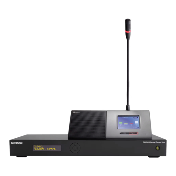
Page 6: Dis-Ccu Central Control Unit
The DIS-CCU operates standard in 5900 mode for use in a DCS 5900 system. By uploading a feature license, the DIS- CCU can operate in 6000 mode for use in a DCS 6000 system. This manual describes the DIS-CCU when operating in DCS 6000 mode. -
Page 7: Overview
Overview The DIS-CCU Central Unit (CCU) is the system controller for the DDS 5900 Discussion and DCS 6000 Conference Systems. The CCU processes a mixture of microphone units, interpretation stations, and loudspeakers, all on the same network. DIS systems comply with international conference standards, supporting advanced speaker control, interpretation, voting, and conference management for up to 3,800 participants. -
Page 8: Feature Licenses
DIS-CCU. Upgrading Legacy DIS CUs Shure provides a free upgrade for legacy DIS CUs to add features that are now included as standard with the DIS-CCU. Contact your local Shure sales representative to obtain the file. The CU 5905 upgrades to the following features: •... -
Page 9: Adding The License To The Dis-Ccu
DIS-CCU. The unit will reboot. After Installing the License File The features are listed at the top of the web page and the mode is selectable for operation with the DDS 5900 or DCS 6000 system. -
Page 10: Select The System Mode
Select the System Mode A unit with the DCS 6000 license installed can operate for either DDS 5900 or DCS 6000 system. In 5900 mode, the additional feature licenses are disabled. Note: Microphone units cannot be mixed across systems; DDS 5900 microphone units only operate in DDS 5900 system mode, and DCS 6000 units operate in DCS 6000 mode. -
Page 11: Dis-Ccu Hardware Description
DIS-CCU Hardware Description DIS-CCU Central Control Unit TCP/IP Out A Out B Out C Out D Out E Out F Out G Out H DIS-CCU Central Unit Front Panel ⑥ Control Connector (TCP/IP) The RJ45 connector allows access to the built-in web ①... -
Page 12: Rackmounting The Ccu
Rackmounting the CCU Install the central control unit in a standard 19” rack using the supplied 19” brackets. Remove the screws holding the top and bottom covers, then attach the brackets to the front of the unit using the same screws. Important: Use the two 10 mm length self-threading screws closest to the front and the 8 mm length threaded screw furthest from the front. -
Page 13: Menu Navigation
System License Info 250/3800 Max. Conf. Units Licensed 4 to 31 Max. Intp. Channels 6000 Operation License Available Select 5900 System OK/Cancel x.x.xxx FW Release ID Serial Number xxx.xxx.xxx Restore Factory Defaults OK/Cancel Menu Overview - DCS 6000 Mode... -
Page 14: Connecting The Dcs-Lan Equipment
Connecting the DCS-LAN Equipment Shure offers cables designed specifically for the DIS line of conferencing and discussion equipment. The Shure EC 6001 are high-quality Ethernet cables available various lengths from 0.5 m to 100 m. Each cable has been tested to ensure reliable system performance. -
Page 15: Dcs 6000 Cable Requirements
• DIS-CCU with repeater units: 680 m Important: Cables and connectors must be shielded for stable system performance. If an installation does not use Shure EC 6001 cables, they must follow the Cat5e cable requirements. Using Patch Panels When designing a system with a patch panel, crimp the cable to the female shielded connector on the panel. Then simply use short jumper cables to connect to the microphone units. - Page 16 Properly Securing Cables As with any cable carrying a signal, use care when installing the equipment. Bending Rule Do not sharply bend the cable. Ethernet cables cannot bend more than four-times the diameter of the cable. Pinching Do not over-fasten the cable. A pinched cable may not operate correctly.
-
Page 17: Connection Diagrams
Connection Diagrams The following system diagrams illustrate typical hardware connections to the DIS-CCU central control unit. Actual installations may use different combinations of hardware, but follow the general concepts outlined below. Note: Flushmount and portable microphone units are interchangeable in the following drawings, unless noted. Basic Setup with Microphone Units The system is operational without the use of a computer. - Page 18 Wireless Control Interpretation Units The DCS 6000 system supports simultaneous interpretation for up to 31 languages, routing the interpretation channels to each microphone unit. Typically, a separate room or booth is dedicated for interpreters for greater sound isolation. Interpreter Stations...
- Page 19 Connect a mixer to the CCU analog outputs to control individual microphone volume or equalization. Use the browser interface to buss units to groups and assign them to the specific output (A-H). To return the audio to the DCS 6000 system: 1. Connect the output of the external device to Audio Input 1 on the CCU 2.
-
Page 20: Wireless Language Distribution
For additional monitoring, connect a wireless language distribution system to one of the CCU audio outputs. Use the browser interface to select the desired microphones (seat) for that group output (A-H). The DCS 6000 Digital Infrared Language System transmits this audio signal to a number of listening stations. -
Page 21: Power Requirements
Power Requirements For many installations, the DIS-CCU supplies sufficient power for the microphone units. Depending on the setup, the CCU powers up to 50 units at a time without additional equipment. The number of supported microphone units depends on the size and layout of the installation. - Page 22 Units Supported by the DIS-CCU The following tables provide estimates to the number of conference units powered by the CCU without additional equipment. All units in a system should be tested after installation to ensure that enough power is supplied to each unit. When using multiple chain outputs, arrange the same number of conference units on each chain..
- Page 23 CM/DM 6080 F / DM 6620 F Chairman/Delegate 1 m Spacing Between Microphone Units Cable Length Maximum Number of Microphone Units CCU to the first unit Total One Chain 10 m 39 m 30 m 56 m 50 m 73 m 100 m 115 m 150 m...
- Page 24 MU 6040 C/D and MU 6042 D The following numbers when no loudspeaker is connected. If loudspeakers are used, then use the tables for DC 6120 P or DC 6190 P. 1 m Spacing Between Microphone Units Cable Length Maximum Number of Microphone Units CCU to the first unit Total One Chain...
- Page 25 CS 6340 F Channel Selector These estimates are for units with the back light on. 1 m Spacing Between Units Cable Length Maximum Number of Units CCU to the first unit Total One Chain 30 m 122 m 50 m 129 m 100 m 163 m...
- Page 26 Using Junction Boxes The JB 604 junction box adds four additional outputs to a point on the DCS-LAN chain. These four outputs are available for short-run connections to microphone units, protecting the DCS-LAN chain from technical failures or hot-plugging damage. A single unit can connect to each JB output, with a maximum cable length of 10 m. The following tables show the maximum number of DC 6120 P, DC 6190 P or DM 6680 units.
-
Page 27: Installing Large Systems
Installing Large Systems Power Supplies for Additional Components To add additional components to the system, add an inline or rackmount power supply to the microphone unit chain. Multiple power supplies can be used to reach the maximum 3,800 supported units. Note: To exceed 250 units, make sure the FL6000-3800 license has been purchased and installed in the CCU. - Page 28 Extending Total Cable Length The CCU operates a system with up to 160 m of shielded Cat5e cable. Add an EX 6010 or the RP 6004 Repeater to add more cable for large or more complex installations. The RP 6004 connects anywhere in the DCS-LAN chain, refreshing audio and control data for the units that follow it. It provides four additional chain outputs that each operate for an additional 200 m.
-
Page 29: System Set Up
Note: The computer network is separate from the component network (DCS-LAN). DCS 6000 Web Interface System Requirements For best performance, always update the browser to the latest released version. The following browsers function properly with the system interface: •... - Page 30 Open the DIS-CCU System Interface Follow these instructions to open the browser interface on a computer. TCP/IP Connect to the CCU 1. Connect the computer to the port on the CCU. TCP/IP 2. Power on the equipment. 3. Assign the computer to automatically obtain an IP address. This enables the computer to automatically connect to the CCU.
- Page 31 Assigning the Network Address Access to the system interface is available from two network addresses: IP address and hostname. Typing either address into a browser will access the interface of the connected CU. Manage the network address from the browser: >...
- Page 32 Additional Pages for Meeting Participants In addition to the administrator access to the web interface, there are two separate addresses useful to the participants during the meeting: • Microphone control for speaker management • Display-only page for meeting participants to view the speaker lists Display for participants Microphone control By default, anyone can access these views from a computer or mobile device connected to the network.
- Page 33 Microphone Control Page This page is dedicated for microphone control during the meeting. Use this view as a chairperson or meeting operator to manage speakers, speak requests, and replies. For access, enter the IP address of the CCU, followed by (example: /chairman http://172.17.11.137/chairman...
- Page 34 Display Page The display page is used to provide the meeting participants with a view of the speaker, speak request, and reply lists. For access, enter the IP address of the CCU, followed by (example: /display http://172.17.11.137/display Tip: Put the page in full-screen mode during the meeting: •...
-
Page 35: Language Setting
Language Setting The browser interface is supported in a variety of languages. Go to > to select the desired language. System Language Albanian Shqip Arabic ةيبرعلا ةغللا Bosnian Bosanski Bulgarian български Chinese (Simplified) 中文(简体) Chinese (Traditional) 中文(繁體) Croatian Hrvatski Danish Dansk English English... -
Page 36: Security
Security DIS components use a proprietary codec algorithm to prevent unauthorized devices from listening to the audio signal. To further protect the meeting, assign a password to the browser interface and enable security features on wireless routers. Password Protect the Browser Interface You can assign a password to restrict access to the browser interface. -
Page 37: Assigning Names And Seat Numbers
Assigning Names and Seat Numbers When the meeting begins, the chairman or moderator will need to refer to the participants by either name, seat number, or both. The proper assignment of names and seat numbers is critical to ensure the continuity of the meeting. When logging in with the browser interface to an installation for the first time, each microphone unit appears with its default name. - Page 38 3. Draw a seating chart, or diagram, that represents the room. Number each seat that requires a microphone unit. Add participant names to the seating chart. 4. Go back to the Participant Setup page > and change the descriptions next to the assigned Configuration Participant Setup seat numbers to the appropriate participant names.
-
Page 39: Audio Settings
Audio Settings The Floor Mix When a microphone is turned on, the audio is routed to the main mix (Group A) by default. This mix is often referred to as the floor mix because it transmits the audio from the talker to the rest of the participants in the meeting. Interpreters also listen to the floor to provide language interpretation for multilingual meetings. -
Page 40: Floor Mix On The Loudspeakers
Floor Mix on the Loudspeakers Loudspeakers are included in most microphone units for localized sound-reinforcement of the meeting. When a participant uses their microphone, their speech is heard at other unit loudspeakers. This improves speech clarity in large rooms and reduces typical problems associated with sound reinforcement systems. -
Page 41: Audio Source For The Loudspeaker And Headphones
Audio Source for the Loudspeaker and Headphones By default all microphones are routed to loudspeaker and headphone mixes. To change the audio source: 1. Route microphones to to add them to the floor mix (all selected by default) > Group A Audio Group Setup Group A = Floor... -
Page 42: Analog Audio Outputs
Analog Audio Outputs Eight analog outputs are available for recording, language distribution system, teleconferencing unit, or an external PA system. TCP/IP DIS-CCU Out A Out B Out C Out D Out E Out F Out G Out H Eight Analog Outputs Select the audio source for each analog output Go to >... -
Page 43: Adding An External Audio Source
Adding an External Audio Source Two inputs are available on the DIS-CCU for adding an external audio source to the system, often useful for teleconferencing or internet calling. 1. Connect a line-level audio source, such as the audio output of a computer, teleconferencing unit, or wireless microphone system to the audio input on the DIS-CCU back panel. - Page 44 Emergency Audio Signal To prepare for an emergency, connect an Emergency Evacuation Message (EEM) audio signal to Input 2. The block connector provides a 'normally-open' switch that when closed, distributes the emergency signal to the loudspeakers and all input and output connections. Important: When the switch is used for Input 2, the EEM audio signal bypasses the volume and on/off settings.
-
Page 45: Adding Ambient Sound
Adding Ambient Sound The ambient microphone unit improves the experience of listening to a conference on headphones. The microphone provides natural noise from the room during pauses in a speech or brief breaks between agenda items. This is especially helpful for interpreters or other participants that are not in the same room as the conference. The ambient room sound informs participants that these pauses in speech are not a connection or audio problem. -
Page 46: Participant Microphone Settings
Participant Microphone Settings Several factors may affect the meeting requirements and the manner in which the meeting is run: room size, number of participants, formality of the event, and amount of technical support on staff. Adjust these operation settings in the DIS- CCU to best fit the meeting needs: •... - Page 47 > Operation Operation Mode Change the Operation Mode • CCU hardware: > Operation Operation Mode • Browser interface: > or from the page Operation Operation Mode Microphone Control...
-
Page 48: Replies
Replies The reply mode enables participants to briefly comment or ask a question to the present speaker. This allows a concise follow-up to the speaker without affecting the request queue. On the participant microphone unit, the left button is reprogrammed to operate as a reply button. The participant presses the reply button to add themselves to the reply list, and the chairman or operator manually activates the reply. -
Page 49: Number Of Active Microphones
Number of Active Microphones To improve speaker management and clarity of the audio, there is a limit to the number of speakers at the same time. The number of active microphones is adjustable from 1 - 8. Once the limit is reached, a participant trying to turn on the microphone may be added to a request queue or denied access, depending on the microphone operating mode. -
Page 50: Interrupt Mode
Example Settings Chairman (Moderator) Can Speak At Any Time Set the total number of speakers to one (1) higher than the maximum number of participants. If there are two chairmen, set the number to two (2) higher. Using FIFO Mode First In, First Out (FIFO) mode automatically turns on microphones based on a chronological queue list. -
Page 51: Voice Detection
Voice Detection Release Time Adjust voice detection settings from > Operation Determines how long a microphone remains active after Voice Detection a participant stops talking. The setting is selectable in 0.5 second increments. Default 4 seconds Minimum 1 seconds Maximum 10 seconds Book Drop To ensure that only the speech from a participant activates the microphone, turn on the book drop feature. -
Page 52: Language Interpretation
DIS-CCU, transmitting audio to independent language channels. Participants listen to their language on headphones connected to the microphone unit. 4 languages are provided with the DCS 6000 mode license, and can expand to 8, 16, or 31 with an additional license. Booth 1... -
Page 53: Wireless Language Distribution
Use the browser interface to route the desired interpretation channels or a subset of microphones to that group output. The DCS 6000 Digital Infrared Language System transmits this audio signal to a number of portable listening devices. Analog outputs to digital transmitter... -
Page 54: Interpretation Settings
Interpretation Settings Interpreter Interrupt Ability The Interpreter Lock setting applies when multiple people are interpreting the same language. By default, interpreters alternate with each other and cannot override a unit already in use. Note: Interpreters select their primary (A) and secondary (B) languages from the IS 6132 interpreter station. Change the setting from >... -
Page 55: Command Strings For External Controller
Set up a TCP/IP connection to control and monitor the • Setting a microphone in speak or in request DCS 6000 from an external interface. Controllers such as • Retrieving a list of seats available in the system. or Crestron connect to the DIS-CCU using a simple ®... -
Page 56: Voting Control
Command Structure (from DIS-CCU to Example: When a 'mic_on' command results in a External Control) microphone being turned on, the CCU replies with a 'mic_on' command. On the other hand, if a 'mic_on' Command lines out of the DIS-CCU are just as simple: command does not lead to turning on a microphone, <command><SP><data><CR><LF>... -
Page 57: Voting Results
Voting Results Example: Voting During voting sessions the CCU delivers interim voting Assume that the DIS-CCU is not controlled by the SW 6000 results, unless the session is secret. ExtCtrl At completion of a voting session, the CCU delivers final voting results. - Page 58 Set the maximum number of delegate If the CCU inserts the unit into the reply list and it issues speakers the 'mic_reply_on' command. max_speakers <max speakers><CR> Remove a microphone from the reply list Maximum number of delegates allowed to speak. mic_reply_off <seat no><CR>...
- Page 59 Ask the CCU to deliver status of the system (microphones <seat no>: the seat number in speak, and microphones in request list). <reply position>: the position in the reply list <reply #>: the reply number in the reply configuration The CCU issues the microphone system status. The status <name>: the seat name or delegate name is a list of commands from the CCU: •...
-
Page 60: Audio Control
<mode> “auto” (Automatic), “fifo” (First-in-first-out), • When the external control application requests “manual” (Manual), “vox” (Voice Active), “auto+reply” microphone status (mic_status) (Automatic+Reply), “manual+reply” (Manual+Reply) and • When a microphone unit becomes lost or found “vox+reply” (Voice Active + Reply) <seat number> The seat number identification of a Interrupt Mode microphone unit. -
Page 61: Loudspeaker Volume
Adjusts the level of the line input 2 signal. This command sets the attenuation of a microphone. <level> The level of line input 2 ranges from -41 to 0. The <seat_number>: The desired microphone value -41 indicates the signal level is zero. Values from -40 <Attenuation>: The desired microphone attenuation. -
Page 62: Voting Commands
Gain can be set to 0 dB or 10 dB. 0 dB will not add any <path> Indicates which connection is being controlled. gain to the line input whereas 10 dB will add 10 dB gain to Possible values are: 'mic_to_speaker', 'mic_to_floor', the line input. - Page 63 Used to cancel an ongoing voting session in the CCU. During a voting session the CCU informs about interim If the voting session is cancelled, the CCU replies with voting results. When new votes are cast, the CCU voting_cancelled. distributes interim voting results. This command informs about one of the interim voting results.
- Page 64 <final_result> contains the interim attendance check result. For a standalone system it indicates how many delegates have pressed the ‘attendance’ button. Voting Configuration voting_configuration<voting_configuration_id><voting_configuration_name><CR> Identifies a voting configuration. <voting_configuration_id> is an integer identifying the voting configuration. <voting_configuration_name> is a name for the configuration. Voting Status complete voting_status_done<CR>...
-
Page 65: Troubleshooting
Troubleshooting Attention: Always use shielded Cat 5e (or higher) network cables for reliable system operation. Ensure the right cables are used and installed correctly before referencing the troubleshooting table. The light rings on the microphone • Check that cables are shielded Cat 5e (or higher) are constantly flashing after the •... -
Page 66: Firmware Update
1. Make sure the system is on and operating properly. • Ethernet: Type the IP address of the CCU and use IP port 2. Download the latest firmware from the Shure website. 3142. The FUU is bundled with the firmware download. -
Page 67: Technical Specifications
Technical Specifications DCS 6000 System Temperature Range The microphone system conforms to IEC 60914, the international standard for conference systems. However the To guarantee specified 5 Deg C. to 40 Deg C. functionality of an Interpreter Unit differs from the standard. -
Page 68: Wiring Details
Wiring Details Main Power Analog Audio Out XLR3 male Blue Neutral Brown Live Signal Cable type Green/Yellow Earth (Ground) Earth 2 x 0.25 mm2 shielded. Signal + Signal – DCS-LAN Chain The DIS-CCU uses Cat5e, Cat6 or Cat7 F/UTP or U/FTP cables with shielded RJ45 connectors. -
Page 69: How To Order
Central control unit for the DIS lines of discussion and conferencing systems. Operates with the DDS 5900 system as shipped, and is upgradeable for the DCS 6000 system with a feature license. Includes a web interface for system configuration, microphone control, and displaying the speaker list during the meeting. -
Page 70: Ps-Ccu Power Supply
Taiwan PS-CCU-UK Pre-Tested Shure Cables Shure offers individually-tested cables for Shure conferencing and discussion equipment. The EC 6001 are high-quality, shielded Cat5e cables available various lengths from 0.5 m to 100 m. Made with male-to-male shielded connectors. Male-to-Male Patch Cables 0.5 m black shielded Cat5e F/UTP cable (shielded RJ45) EC 6001-0.5... -
Page 71: Advanced Setup
Advanced Setup Distribution box with 4 outputs. DCS 6000 and DDS 5900 systems JB 6104 DCS-LAN extension unit for additional 160 conference units EX 6010 Inline data repeater for DCS–LAN network; 1 input x 4 outputs RP 6004 Inline power supply for up to 40 additional discussion units. See PI-6001 table for regional variations.
Need help?
Do you have a question about the DCS 6000 and is the answer not in the manual?
Questions and answers