Advertisement
Quick Links
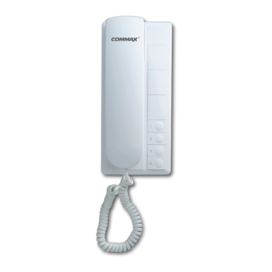
TP–nKP
Cautions for installation
1. Total connected cable length shouldn't be over 1km between first & last product (0.65m/m)
2. Be sure not to change the wiring sequence.
Troubleshooting
1. A voice through the phones feels quite low or they are not working at all.
▶ Test total three interphones with short wires than normal or connected 1 more power source.
2. It doesn't make a call to the targeted interphone
▶ Check the connection wire "L" on "Terminal BOX".
3. A certain unit does not work properly.
▶ Change each unit to check which one makes malfunction.
Wiring Diagram
STA1
STA2
STA3
STA4
STA5
STA10
Own No. Terminal
Common Talk Terminal
Paging Terminal
External Speaker
Installation manual
1. Installation tools & parts : Nipper, Screw driver, UTP cable(Cat 6.E)
2. Products: TP-4/6/10KP , RF-1A
3. Wiring & setting method
3-1. Put TP-4/6/10KP on the place to install and open the cover of
"Terminal BOX".
3-2. Unscrew slightly 1~4,6,10th,L1,+,-P,-1 with screw driver
▶From first interphone to the last one all connectors should be connected in
parallel except "L","-1"
▶First interphone : Move the wire on "1" terminal to "L" terminal.
Make "P" and "1" terminals in short.
▶Second interphone : Move the wire on "2" terminal to "L" terminal.
Make "P" and "2" terminals in short.
▶ tenth interphone : Move the wire on "10" terminal to "L" terminal.
Make "P" and "10" terminals in short.
3-3. After complete wiring, screw them all tightly.
3-4. Connect "RF-1A" to separate + , - terminals
* For additional speakers, refer to user manual
Advertisement

Summary of Contents for Commax TP–nKP
- Page 1 TP–nKP Installation manual 1. Installation tools & parts : Nipper, Screw driver, UTP cable(Cat 6.E) 2. Products: TP-4/6/10KP , RF-1A 3. Wiring & setting method 3-1. Put TP-4/6/10KP on the place to install and open the cover of “Terminal BOX”. 3-2.
- Page 2 C-MIC ▶ HOOK S/W ▶ IC1 3rd pin ▶ IC1 5th pin ▶ HOOK S/W ▶ T1 Trans ▶ Output through “L1” Deliver a voice message 3. Receiving a call Pick up the phone “L1” terminal ▶ T1 Trans ▶ HOOK S/W ▶ Speaker Listening WWW.COMMAX.COM...


Need help?
Do you have a question about the TP–nKP and is the answer not in the manual?
Questions and answers