Table of Contents
Advertisement
file:///C|/Documents%20and%20Settings/Administrator/Plocha/PANASONIC%20SA-PM27E/s0000000000.htm
Service Manual
TOP NEXT
Order No. MD0206158C2
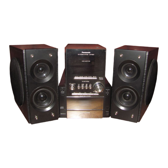
CD Stereo System
SA-PM27E
SA-PM27EB
SA-PM27EG
Colour
(K) ... Black Type
file:///C|/Documents%20and%20Settings/Administrator/Plocha/PANASONIC%20SA-PM27E/s0000000000.htm (1 of 3) [14.6.2003 18:23:08]
Specification
Amplifier Section
RMS Power output
10% Total harmonic distortion
100 Hz, both channels driven (Low channel)
1 kHz, both channels driven (High channel)
Total Bi-Amp power
Input sensitivity
AUX
Input impedance
AUX
FM Tuner Section
Frequency range
87.50-108.00 MHz (50 kHz steps)
Sensitivity
S/N 26 dB
Antenna terminal(s)
AM Tuner Section
Frequency range
522-1629 kHz (9 kHz steps)
Sensitivity
S/N 20 dB (at 999 kHz)
30 W per channel (6Ω)
30 W per channel (6Ω)
60 W per channel
250 mV
11.8 kΩ
1.8•V (IHF)
1.5•V
75Ω (unbalanced)
560•V/m
Advertisement
Table of Contents

Related Manuals for Panasonic SA-PM27E


Summary of Contents for Panasonic SA-PM27E
- Page 1 87.50-108.00 MHz (50 kHz steps) Sensitivity 1.8•V (IHF) S/N 26 dB 1.5•V Antenna terminal(s) 75Ω (unbalanced) AM Tuner Section Frequency range 522-1629 kHz (9 kHz steps) Sensitivity S/N 20 dB (at 999 kHz) 560•V/m file:///C|/Documents%20and%20Settings/Administrator/Plocha/PANASONIC%20SA-PM27E/s0000000000.htm (1 of 3) [14.6.2003 18:23:08]...
- Page 2 Mass and dimensions are approximate. Total harmonic distortion is measured by the digital spectrum analyzer. © 2002 Matsushita Electronics (S) Pte. Ltd. All rights reserved. Unauthorized copying and distribution is a violation of law. file:///C|/Documents%20and%20Settings/Administrator/Plocha/PANASONIC%20SA-PM27E/s0000000000.htm (2 of 3) [14.6.2003 18:23:08]...
-
Page 3: Before Repair And Adjustment
After repairs are completed, restore power gradually using a variac, to avoid over current. Current consumption at AC 230 V, 50 Hz in NO SIGNAL mode should be ~300 mA. TOP PREVIOUS NEXT file:///C|/Documents%20and%20Settings/Administrator/Plocha/PANASONIC%20SA-PM27E/s0100000000x.htm [14.6.2003 18:24:11]... -
Page 4: Protection Circuitry
2. Determine the cause of the problem and correct it. 3. Turn on the power once again after one minute. Note: When the protection circuitry functions, the unit will not operate unless the power is first turned off and then on again. TOP PREVIOUS NEXT file:///C|/Documents%20and%20Settings/Administrator/Plocha/PANASONIC%20SA-PM27E/s0200000000x.htm [14.6.2003 18:24:38]... - Page 5 3 Accessories TOP PREVIOUS NEXT AC Mains lead (E/EG)..1 pc AC Mains lead (EB)..1 pc AM Loop Antenna..1 pc FM Indoor Antenna..1 pc file:///C|/Documents%20and%20Settings/Administrator/Plocha/PANASONIC%20SA-PM27E/s0300000000x.htm (1 of 2) [14.6.2003 18:25:03]...
- Page 6 Antenna Plug Adaptor..1 pc (EB only) Remote Control Transmitter..1 pc TOP PREVIOUS NEXT file:///C|/Documents%20and%20Settings/Administrator/Plocha/PANASONIC%20SA-PM27E/s0300000000x.htm (2 of 2) [14.6.2003 18:25:03]...
-
Page 7: Caution For Ac Mains Lead
4 Caution for AC Mains Lead TOP PREVIOUS NEXT file:///C|/Documents%20and%20Settings/Administrator/Plocha/PANASONIC%20SA-PM27E/s0400000000x.htm (1 of 2) [14.6.2003 18:25:35]... - Page 8 This unit is equipped with a self-diagnostic display function, which will be useful during servicing and maintenance. Refer to the next page for display symbols, symptoms, etc. 5.1 Preparations 5.2 Setting of the Self-Diagnostic Mode 5.3 Restoring Normal Display 5.4 Clearing Self-Diagnostic Memory 5.5 Displaying Self-Diagnostic Results TOP PREVIOUS NEXT file:///C|/Documents%20and%20Settings/Administrator/Plocha/PANASONIC%20SA-PM27E/s0500000000x.htm [14.6.2003 18:25:57]...
- Page 9 1. A Cr02-positioned blank cassette tape with an erase prevention niche on either Side A or B. 2. A normal-positioned music tape with erase prevention niches on both Sides A and B. Both tapes are halfway forwarded in advance. 3. The remote controller that comes with this unit. TOP PREVIOUS NEXT file:///C|/Documents%20and%20Settings/Administrator/Plocha/PANASONIC%20SA-PM27E/s0501000000.htm [14.6.2003 18:26:20]...
- Page 10 5.2 Setting of the Self-Diagnostic Mode TOP PREVIOUS NEXT TOP PREVIOUS NEXT file:///C|/Documents%20and%20Settings/Administrator/Plocha/PANASONIC%20SA-PM27E/s0502000000.htm [14.6.2003 18:26:45]...
- Page 11 From the F76 display, the normal display does not appear till an error is recovered. For displays other than F76, press “POWER” button to turn off the power, and then turn on the power. TOP PREVIOUS NEXT file:///C|/Documents%20and%20Settings/Administrator/Plocha/PANASONIC%20SA-PM27E/s0503000000.htm [14.6.2003 18:27:07]...
- Page 12 /-DEMO" button is pressing repeatedly. (e.g. H01 CD F15 F01) If no error is found, only "TEST" indication is displayed and remains unchange even if " /-DEMO" button is pressed. TOP PREVIOUS NEXT file:///C|/Documents%20and%20Settings/Administrator/Plocha/PANASONIC%20SA-PM27E/s0504000000.htm [14.6.2003 18:27:45]...
- Page 13 6. Remove the cassette tape, and set the other side. 7. Press [ /REW/ ] button. The tape will be rewound and automatically stops after two seconds. 8. Press [ /-DEMO] button on the unit. file:///C|/Documents%20and%20Settings/Administrator/Plocha/PANASONIC%20SA-PM27E/s0505000000.htm (1 of 3) [14.6.2003 18:28:08]...
- Page 14 A blank section that lasts only 4 seconds or less. No blank sections (recording through microphones, etc.). Music selections that have extremely low pitches or prolonged silent sections (such as classical music). and/or Music recorded with fade in/out effect. file:///C|/Documents%20and%20Settings/Administrator/Plocha/PANASONIC%20SA-PM27E/s0505000000.htm (2 of 3) [14.6.2003 18:28:08]...
- Page 15 TOP PREVIOUS NEXT file:///C|/Documents%20and%20Settings/Administrator/Plocha/PANASONIC%20SA-PM27E/s0505000000.htm (3 of 3) [14.6.2003 18:28:08]...
-
Page 16: Handling Precautions For Traverse Deck
Caution: The static electricity of your clothes will not be grounded through the wrist strap. So, take care not to let your clothes touch the traverse deck (optical pickup). file:///C|/Documents%20and%20Settings/Administrator/Plocha/PANASONIC%20SA-PM27E/s0600000000x.htm (1 of 2) [14.6.2003 18:28:31]... - Page 17 The traverse deck has a short point shorted with solder to protect the laser diode against electrostatics breakdown. Be sure to remove the solder from the short point before making connections. TOP PREVIOUS NEXT file:///C|/Documents%20and%20Settings/Administrator/Plocha/PANASONIC%20SA-PM27E/s0600000000x.htm (2 of 2) [14.6.2003 18:28:31]...
-
Page 18: Precaution Of Laser Diode
2. Den werkseitig justierten Einstellregler der Lasereinhit nicht verstellen. 3. Nicht mit optischen Instrumenten in die Fokussierlinse blicken. 4. Nicht über längere Zeit in die Fokussierlinse blicken. ADVARSEL: I dette a apparat anvendes laser. file:///C|/Documents%20and%20Settings/Administrator/Plocha/PANASONIC%20SA-PM27E/s0700000000x.htm (1 of 2) [14.6.2003 18:28:52]... - Page 19 CAUTION! THIS PRODUCT UTILIZES A LASER. USE OF CONTROLS OR ADJUSTMENTS OR PERFORMANCE OF PROCEDURES OTHER THAN THOSE SPECIFIED HEREIN MAY RESULT IN HAZARDOUS RADIATION EXPOSURE. Use of Caution Labels TOP PREVIOUS NEXT file:///C|/Documents%20and%20Settings/Administrator/Plocha/PANASONIC%20SA-PM27E/s0700000000x.htm (2 of 2) [14.6.2003 18:28:52]...
-
Page 20: Front Panel Controls
8 Front Panel Controls TOP PREVIOUS NEXT file:///C|/Documents%20and%20Settings/Administrator/Plocha/PANASONIC%20SA-PM27E/s0800000000o.htm (1 of 2) [14.6.2003 18:29:16]... - Page 21 TOP PREVIOUS NEXT file:///C|/Documents%20and%20Settings/Administrator/Plocha/PANASONIC%20SA-PM27E/s0800000000o.htm (2 of 2) [14.6.2003 18:29:16]...
- Page 22 2. Procedure of replacing Pinch Roller and Head Block (Cassette Mechanism Unit) 3. Procedure of replacing Motor, Capstan Belt A, Capstan Belt B and Winding Belt (Cassette Mechanism Unit) 4. Procedure of replacing Parts on Mechanism P.C.B file:///C|/Documents%20and%20Settings/Administrator/Plocha/PANASONIC%20SA-PM27E/s0900000000e.htm (1 of 3) [14.6.2003 18:29:41]...
- Page 23 9.3 Procedure for Replacing Pinch Roller and Head Block (Cassette Mechanism Unit) 9.4 Procedure for Replacing Motor, Capstan Belt A, Capstan Belt B, and Winding Belt (Cassette Mechanism Unit) 9.5 Procedure for Replacing Parts on Mechanism PCB 9.6 Replacement of CD traverse deck file:///C|/Documents%20and%20Settings/Administrator/Plocha/PANASONIC%20SA-PM27E/s0900000000e.htm (2 of 3) [14.6.2003 18:29:41]...
-
Page 24: Table Of Contents
9.12 Disassembly of CD loading section 9.13 Assembly of CD loading unit 9.13.1 Notes on fixing of CD loading section 9.14 Disassembly of traverse mechanism 9.15 Handling of cassette tape jam TOP PREVIOUS NEXT file:///C|/Documents%20and%20Settings/Administrator/Plocha/PANASONIC%20SA-PM27E/s0900000000e.htm (3 of 3) [14.6.2003 18:29:41]... - Page 25 9.1 Disassembly Procedure for each major P.C.B. TOP PREVIOUS NEXT Step 1 & 2 Remove all the screws. file:///C|/Documents%20and%20Settings/Administrator/Plocha/PANASONIC%20SA-PM27E/s0901000000.htm (1 of 9) [14.6.2003 18:30:10]...
- Page 26 Step 3 Remove all the screws and pull up the cassette lid as the arrow shown. Step 4 Release the connectors CN307, CN308 and CN1303. Remove the cassette lid. file:///C|/Documents%20and%20Settings/Administrator/Plocha/PANASONIC%20SA-PM27E/s0901000000.htm (2 of 9) [14.6.2003 18:30:10]...
- Page 27 Step 5 Release the connector CN310 and pull out the back cover as the arrow shown. Step 6 Release the connectors CN504, CN305 and CN301. file:///C|/Documents%20and%20Settings/Administrator/Plocha/PANASONIC%20SA-PM27E/s0901000000.htm (3 of 9) [14.6.2003 18:30:10]...
- Page 28 Step 7 Release the connectors CN606, CN602, CN505, CN500 and remove all the screws. file:///C|/Documents%20and%20Settings/Administrator/Plocha/PANASONIC%20SA-PM27E/s0901000000.htm (4 of 9) [14.6.2003 18:30:10]...
- Page 29 Step 8 Remove all the screws. Step 9 Release the catches and pull out the front panel as the arrow shown. file:///C|/Documents%20and%20Settings/Administrator/Plocha/PANASONIC%20SA-PM27E/s0901000000.htm (5 of 9) [14.6.2003 18:30:10]...
- Page 30 Step 10 Remove all the screws and release the connector CN607A. file:///C|/Documents%20and%20Settings/Administrator/Plocha/PANASONIC%20SA-PM27E/s0901000000.htm (6 of 9) [14.6.2003 18:30:10]...
- Page 31 Steps 11 & 12 Remove all the screws. file:///C|/Documents%20and%20Settings/Administrator/Plocha/PANASONIC%20SA-PM27E/s0901000000.htm (7 of 9) [14.6.2003 18:30:10]...
- Page 32 Step 13 Remove all the screws and pull up the cover as the arrow shown. Step 14 Remove all the screws. file:///C|/Documents%20and%20Settings/Administrator/Plocha/PANASONIC%20SA-PM27E/s0901000000.htm (8 of 9) [14.6.2003 18:30:10]...
- Page 33 Step 15 Reconnect all the connectors back to do the testing. TOP PREVIOUS NEXT file:///C|/Documents%20and%20Settings/Administrator/Plocha/PANASONIC%20SA-PM27E/s0901000000.htm (9 of 9) [14.6.2003 18:30:10]...
- Page 34 9.2 Procedure for Replacing Cassette Holder TOP PREVIOUS NEXT Follow Steps 1 to 4 described in Item 9.1. Step 2 Press the lever to open the cassette cover. file:///C|/Documents%20and%20Settings/Administrator/Plocha/PANASONIC%20SA-PM27E/s0902000000.htm (1 of 2) [14.6.2003 18:30:38]...
- Page 35 TOP PREVIOUS NEXT file:///C|/Documents%20and%20Settings/Administrator/Plocha/PANASONIC%20SA-PM27E/s0902000000.htm (2 of 2) [14.6.2003 18:30:38]...
- Page 36 9.3 Procedure for Replacing Pinch Roller and Head Block (Cassette Mechanism Unit) TOP PREVIOUS NEXT Follow Steps 1 to 4 described in Item 9.1. Follow Steps 1 to 3 described in Item 9.2. file:///C|/Documents%20and%20Settings/Administrator/Plocha/PANASONIC%20SA-PM27E/s0903000000.htm (1 of 2) [14.6.2003 18:31:00]...
- Page 37 TOP PREVIOUS NEXT file:///C|/Documents%20and%20Settings/Administrator/Plocha/PANASONIC%20SA-PM27E/s0903000000.htm (2 of 2) [14.6.2003 18:31:00]...
- Page 38 Winding Belt (Cassette Mechanism Unit) TOP PREVIOUS NEXT Follow Steps 1 to 4 described in Item 9.1. Follow Steps 1 to 3 described in Item 9.2. Follow Steps 2 to 4 described in Item 9.3. file:///C|/Documents%20and%20Settings/Administrator/Plocha/PANASONIC%20SA-PM27E/s0904000000.htm (1 of 4) [14.6.2003 18:31:26]...
- Page 39 (2 of 4) [14.6.2003 18:31:26]...
- Page 40 (3 of 4) [14.6.2003 18:31:26]...
- Page 41 TOP PREVIOUS NEXT file:///C|/Documents%20and%20Settings/Administrator/Plocha/PANASONIC%20SA-PM27E/s0904000000.htm (4 of 4) [14.6.2003 18:31:26]...
- Page 42 9.5 Procedure for Replacing Parts on Mechanism PCB TOP PREVIOUS NEXT Follow Steps 1 to 4 described in Item 9.1. Follow Steps 1 to 3 described in Item9.2. Follow Steps 2 to 4 described in Item 9.3. TOP PREVIOUS NEXT file:///C|/Documents%20and%20Settings/Administrator/Plocha/PANASONIC%20SA-PM27E/s0905000000.htm [14.6.2003 18:31:46]...
- Page 43 9.6 Replacement of CD traverse deck TOP PREVIOUS NEXT Follow Steps 1 to 14 described in Item 9.1. file:///C|/Documents%20and%20Settings/Administrator/Plocha/PANASONIC%20SA-PM27E/s0906000000.htm (1 of 2) [14.6.2003 18:32:56]...
- Page 44 TOP PREVIOUS NEXT file:///C|/Documents%20and%20Settings/Administrator/Plocha/PANASONIC%20SA-PM27E/s0906000000.htm (2 of 2) [14.6.2003 18:32:56]...
-
Page 45: Replacement Of Optical Pickup Unit (Cd Mechanism)
9.7 Replacement of optical pickup unit (CD mechanism) TOP PREVIOUS NEXT Follow Steps 1 to 14 described in Item 9.1. Follow Steps 1 to 2 described in Item 9.6. file:///C|/Documents%20and%20Settings/Administrator/Plocha/PANASONIC%20SA-PM27E/s0907000000.htm (1 of 8) [14.6.2003 18:33:20]... - Page 46 (2 of 8) [14.6.2003 18:33:20]...
- Page 47 (3 of 8) [14.6.2003 18:33:20]...
- Page 48 (4 of 8) [14.6.2003 18:33:20]...
- Page 49 (5 of 8) [14.6.2003 18:33:20]...
- Page 50 (6 of 8) [14.6.2003 18:33:20]...
- Page 51 (7 of 8) [14.6.2003 18:33:20]...
- Page 52 TOP PREVIOUS NEXT file:///C|/Documents%20and%20Settings/Administrator/Plocha/PANASONIC%20SA-PM27E/s0907000000.htm (8 of 8) [14.6.2003 18:33:20]...
-
Page 53: Replacement Of A Traverse Gear A And A Traverse Gear B
B TOP PREVIOUS NEXT Follow Steps 1 to 14 described in Item 9.1. Follow Steps 1 to 2 described in Item 9.6. Follow Steps 1 to 12 described in Item 9.7. file:///C|/Documents%20and%20Settings/Administrator/Plocha/PANASONIC%20SA-PM27E/s0908000000.htm (1 of 3) [14.6.2003 18:33:41]... - Page 54 (2 of 3) [14.6.2003 18:33:41]...
- Page 55 TOP PREVIOUS NEXT file:///C|/Documents%20and%20Settings/Administrator/Plocha/PANASONIC%20SA-PM27E/s0908000000.htm (3 of 3) [14.6.2003 18:33:41]...
-
Page 56: Disassembly Of Cd Loading Unit
9.9 Disassembly of CD loading unit TOP PREVIOUS NEXT 9.9.1 Regarding a jig "gear" TOP PREVIOUS NEXT file:///C|/Documents%20and%20Settings/Administrator/Plocha/PANASONIC%20SA-PM27E/s0909000000.htm [14.6.2003 18:34:08]... -
Page 57: Regarding A Jig "Gear
"gear" as it may possibly not be attached at the top cover part becauseit is already used. 1. Remove the gear attached to the top cover of CD loading mechanism. 2. Insert a hexagonal wrench of 2.5mm (opposite side diameter) into the gear. file:///C|/Documents%20and%20Settings/Administrator/Plocha/PANASONIC%20SA-PM27E/s0909010000.htm (1 of 2) [14.6.2003 18:34:31]... - Page 58 TOP PREVIOUS NEXT file:///C|/Documents%20and%20Settings/Administrator/Plocha/PANASONIC%20SA-PM27E/s0909010000.htm (2 of 2) [14.6.2003 18:34:31]...
-
Page 59: Replacement Of Disk Tray
9.10 Replacement of disk tray TOP PREVIOUS NEXT Follow Steps 1 to 14 described in Item 9.1. file:///C|/Documents%20and%20Settings/Administrator/Plocha/PANASONIC%20SA-PM27E/s0910000000.htm (1 of 7) [14.6.2003 18:34:57]... - Page 60 (2 of 7) [14.6.2003 18:34:57]...
- Page 61 (3 of 7) [14.6.2003 18:34:57]...
- Page 62 (4 of 7) [14.6.2003 18:34:57]...
- Page 63 (5 of 7) [14.6.2003 18:34:57]...
- Page 64 (6 of 7) [14.6.2003 18:34:57]...
- Page 65 TOP PREVIOUS NEXT file:///C|/Documents%20and%20Settings/Administrator/Plocha/PANASONIC%20SA-PM27E/s0910000000.htm (7 of 7) [14.6.2003 18:34:57]...
-
Page 66: Replacement Of The Traverse Mechanism
9.11 Replacement of the traverse mechanism TOP PREVIOUS NEXT Follow Steps 1 to 7 described in Item 9.10. file:///C|/Documents%20and%20Settings/Administrator/Plocha/PANASONIC%20SA-PM27E/s0911000000.htm (1 of 2) [14.6.2003 18:35:23]... -
Page 67: Disassembly Of Cd Loading Section
9.12 Disassembly of CD loading section TOP PREVIOUS NEXT Follow Steps 1 to 7 described in Item 9.10. Follow Step 1 described in Item 9.11. file:///C|/Documents%20and%20Settings/Administrator/Plocha/PANASONIC%20SA-PM27E/s0912000000.htm (1 of 10) [14.6.2003 18:35:45]... - Page 68 (2 of 10) [14.6.2003 18:35:45]...
- Page 69 (3 of 10) [14.6.2003 18:35:45]...
- Page 70 (4 of 10) [14.6.2003 18:35:45]...
- Page 71 (5 of 10) [14.6.2003 18:35:45]...
- Page 72 (6 of 10) [14.6.2003 18:35:45]...
- Page 73 (7 of 10) [14.6.2003 18:35:45]...
- Page 74 (8 of 10) [14.6.2003 18:35:45]...
- Page 75 (9 of 10) [14.6.2003 18:35:45]...
- Page 76 TOP PREVIOUS NEXT file:///C|/Documents%20and%20Settings/Adminis...r/Plocha/PANASONIC%20SA-PM27E/s0912000000.htm (10 of 10) [14.6.2003 18:35:45]...
-
Page 77: Assembly Of Cd Loading Unit
For assembly of CD loading unit, follow the reverse way of the disassembly procedure. And see following procedure as there are some points to be noticed in the assembly. 9.13.1 Notes on fixing of CD loading section TOP PREVIOUS NEXT file:///C|/Documents%20and%20Settings/Administrator/Plocha/PANASONIC%20SA-PM27E/s0913000000.htm [14.6.2003 18:36:09]... -
Page 78: Notes On Fixing Of Cd Loading Section
1. Set a marking of a select drive gear at a marking of a mechanism base. 2. Fix a select gear 3. Slide a select track as shown by the arrow and fit it to a select gear. file:///C|/Documents%20and%20Settings/Administrator/Plocha/PANASONIC%20SA-PM27E/s0913010000.htm (1 of 26) [14.6.2003 18:36:37]... - Page 79 4. Draw up a select track at the edge of the rear side. file:///C|/Documents%20and%20Settings/Administrator/Plocha/PANASONIC%20SA-PM27E/s0913010000.htm (2 of 26) [14.6.2003 18:36:37]...
- Page 80 9.13.1.2 Notes on fixture of a vertical drive gear and GENEVA gear 1. Fix a vertical drive gear, GENEVA gear, a vertical reduction gear, gears (2 pieces) and a relay gear. file:///C|/Documents%20and%20Settings/Administrator/Plocha/PANASONIC%20SA-PM27E/s0913010000.htm (3 of 26) [14.6.2003 18:36:37]...
- Page 81 2. The marking should be at the position as shown below figure to fix a vertical drive gear. file:///C|/Documents%20and%20Settings/Administrator/Plocha/PANASONIC%20SA-PM27E/s0913010000.htm (4 of 26) [14.6.2003 18:36:37]...
- Page 82 3. Set a hole as shown below to fix GENEVA gear. file:///C|/Documents%20and%20Settings/Administrator/Plocha/PANASONIC%20SA-PM27E/s0913010000.htm (5 of 26) [14.6.2003 18:36:37]...
- Page 83 9.13.1.3 Notes on fixing a vertical rack (L) 1. Fix vertical rack (L) and (R). file:///C|/Documents%20and%20Settings/Administrator/Plocha/PANASONIC%20SA-PM27E/s0913010000.htm (6 of 26) [14.6.2003 18:36:37]...
- Page 84 2. Position the concave portion of a vertical rack (L) to trapezoidal cog of a vertical rack (L) and fix. file:///C|/Documents%20and%20Settings/Administrator/Plocha/PANASONIC%20SA-PM27E/s0913010000.htm (7 of 26) [14.6.2003 18:36:37]...
- Page 85 3. Fix a timing gear plate and a timing gear, then fasten them with screws. file:///C|/Documents%20and%20Settings/Administrator/Plocha/PANASONIC%20SA-PM27E/s0913010000.htm (8 of 26) [14.6.2003 18:36:37]...
- Page 86 9.13.1.4 Notes on fixing of a change gear and a main gear 1. Fix a change lever and a change gear following 2. Then fix a level drive gear and a main gear spring, and fix a main gear following 3 and 4. file:///C|/Documents%20and%20Settings/Administrator/Plocha/PANASONIC%20SA-PM27E/s0913010000.htm (9 of 26) [14.6.2003 18:36:37]...
- Page 87 2. Position a convex portion of a change gear to a marking of a mechanism base and fix. file:///C|/Documents%20and%20Settings/Adminis...r/Plocha/PANASONIC%20SA-PM27E/s0913010000.htm (10 of 26) [14.6.2003 18:36:37]...
- Page 88 3. Position a hole of a main gear against a boss (a) of a mechanism base and fix. 4. Rotate a main gear to the arrow direction to position a hole of a main gear to a boss (b). file:///C|/Documents%20and%20Settings/Adminis...r/Plocha/PANASONIC%20SA-PM27E/s0913010000.htm (11 of 26) [14.6.2003 18:36:37]...
- Page 89 5. Draw up a select rack to the far front part. file:///C|/Documents%20and%20Settings/Adminis...r/Plocha/PANASONIC%20SA-PM27E/s0913010000.htm (12 of 26) [14.6.2003 18:36:37]...
- Page 90 9.13.1.5 Notes on fixing a pitch plate 1. Fix a reduction gear (2), a relay gear, a pulley gear, a tray relaying gear and a large belt (2). file:///C|/Documents%20and%20Settings/Adminis...r/Plocha/PANASONIC%20SA-PM27E/s0913010000.htm (13 of 26) [14.6.2003 18:36:37]...
- Page 91 2. Fix a level reduction gear (1), a horizontal reduction gear (2), a relay gear, a reverse gear, a speedup gear and a small belt (1). file:///C|/Documents%20and%20Settings/Adminis...r/Plocha/PANASONIC%20SA-PM27E/s0913010000.htm (14 of 26) [14.6.2003 18:36:37]...
- Page 92 4. The hole A of a pitch plate should be positioned at the hole of a main gear. (Figure 2) 5. The hole B of a pitch plate should be positioned at the hole of a speedup gear. (Figure 3) 6. Fasten with screws. file:///C|/Documents%20and%20Settings/Adminis...r/Plocha/PANASONIC%20SA-PM27E/s0913010000.htm (15 of 26) [14.6.2003 18:36:37]...
- Page 93 9.13.1.6 Notes on fixing a traverse mechanism 1. Fix a vertical lever. (Fit a rib into both side grooves) file:///C|/Documents%20and%20Settings/Adminis...r/Plocha/PANASONIC%20SA-PM27E/s0913010000.htm (16 of 26) [14.6.2003 18:36:37]...
- Page 94 2. Fit a traverse mechanism into the groove. file:///C|/Documents%20and%20Settings/Adminis...r/Plocha/PANASONIC%20SA-PM27E/s0913010000.htm (17 of 26) [14.6.2003 18:36:37]...
- Page 95 3. The projecting portion of a dividing lever (2) should be inserted into a concave portion of a dividing lever (1). 4. Set a loading gear at the position shown by figure 2. 5. Draw a vertical rack (R) to the arrow direction. file:///C|/Documents%20and%20Settings/Adminis...r/Plocha/PANASONIC%20SA-PM27E/s0913010000.htm (18 of 26) [14.6.2003 18:36:37]...
- Page 96 9.13.1.7 Notes on fixing a disk tray 1. Fix a tray drive gear and a tray drive gear shaft. (Position the lowest rib of a tray drive gear to be level) file:///C|/Documents%20and%20Settings/Adminis...r/Plocha/PANASONIC%20SA-PM27E/s0913010000.htm (19 of 26) [14.6.2003 18:36:37]...
- Page 97 2. Move a tray guide (R) and a tray guide (L) to the arrow direction at a stretch, and fix disk trays (all of 5 pieces). file:///C|/Documents%20and%20Settings/Adminis...r/Plocha/PANASONIC%20SA-PM27E/s0913010000.htm (20 of 26) [14.6.2003 18:36:37]...
- Page 98 D. The hole B of pitch plate should be positioned at a hole of a speedup gear. (Figure 4) E. Set the bottom rib of a tray drive gear to be level. (Figure 5) file:///C|/Documents%20and%20Settings/Adminis...r/Plocha/PANASONIC%20SA-PM27E/s0913010000.htm (21 of 26) [14.6.2003 18:36:37]...
- Page 99 Push in 5 disk trays simultaneously. file:///C|/Documents%20and%20Settings/Adminis...r/Plocha/PANASONIC%20SA-PM27E/s0913010000.htm (22 of 26) [14.6.2003 18:36:37]...
- Page 100 Fix a speedup lock. file:///C|/Documents%20and%20Settings/Adminis...r/Plocha/PANASONIC%20SA-PM27E/s0913010000.htm (23 of 26) [14.6.2003 18:36:37]...
- Page 101 Fix an open switch lever. (Insert a boss of an open switch lever into the hole of mechanism base) file:///C|/Documents%20and%20Settings/Adminis...r/Plocha/PANASONIC%20SA-PM27E/s0913010000.htm (24 of 26) [14.6.2003 18:36:37]...
- Page 102 Fix a top cover. (Fix to the arrow direction after putting into the catch) file:///C|/Documents%20and%20Settings/Adminis...r/Plocha/PANASONIC%20SA-PM27E/s0913010000.htm (25 of 26) [14.6.2003 18:36:37]...
- Page 103 TOP PREVIOUS NEXT file:///C|/Documents%20and%20Settings/Adminis...r/Plocha/PANASONIC%20SA-PM27E/s0913010000.htm (26 of 26) [14.6.2003 18:36:37]...
-
Page 104: Disassembly Of Traverse Mechanism
9.14 Disassembly of traverse mechanism TOP PREVIOUS NEXT Follow Steps 1 to 14 described in Item 9.1. Follow Steps 1 to 7 described in Item 9.10. Follow Step 1 descrbed in Item 9.11. file:///C|/Documents%20and%20Settings/Administrator/Plocha/PANASONIC%20SA-PM27E/s0914000000.htm (1 of 6) [14.6.2003 18:37:03]... - Page 105 (2 of 6) [14.6.2003 18:37:03]...
- Page 106 (3 of 6) [14.6.2003 18:37:03]...
- Page 107 (4 of 6) [14.6.2003 18:37:03]...
- Page 108 (5 of 6) [14.6.2003 18:37:03]...
- Page 109 TOP PREVIOUS NEXT file:///C|/Documents%20and%20Settings/Administrator/Plocha/PANASONIC%20SA-PM27E/s0914000000.htm (6 of 6) [14.6.2003 18:37:03]...
-
Page 110: Handling Of Cassette Tape Jam
9.15 Handling of cassette tape jam TOP PREVIOUS NEXT Follow Steps 1 to 3 described in Item 9.1. file:///C|/Documents%20and%20Settings/Administrator/Plocha/PANASONIC%20SA-PM27E/s0915000000.htm (1 of 2) [14.6.2003 18:37:26]... - Page 111 TOP PREVIOUS NEXT file:///C|/Documents%20and%20Settings/Administrator/Plocha/PANASONIC%20SA-PM27E/s0915000000.htm (2 of 2) [14.6.2003 18:37:26]...
- Page 112 10.1 Operation Check with Cassette Tape 10.1.1 Connection Status between Mechanism and Power Supply (Motor, Plunger) 10.1.2 Operative Parts of Mechanism Unit (EJECT lever fitted with rubber band, Plunger/Rib operation) 10.2 Operation Check without Cassette Tape TOP PREVIOUS NEXT file:///C|/Documents%20and%20Settings/Administrator/Plocha/PANASONIC%20SA-PM27E/s1000000000x.htm [14.6.2003 18:38:05]...
-
Page 113: Operation Check With Cassette Tape
(Note) Other operation may start if a timing of supplying the plunger power is missed. 10.1.1 Connection Status between Mechanism and Power Supply (Motor, Plunger) 10.1.2 Operative Parts of Mechanism Unit (EJECT lever fitted with rubber band, Plunger/Rib operation) TOP PREVIOUS NEXT file:///C|/Documents%20and%20Settings/Administrator/Plocha/PANASONIC%20SA-PM27E/s1001000000.htm [14.6.2003 18:38:29]... - Page 114 10.1.1 Connection Status between Mechanism and Power Supply (Motor, Plunger) TOP PREVIOUS NEXT TOP PREVIOUS NEXT file:///C|/Documents%20and%20Settings/Administrator/Plocha/PANASONIC%20SA-PM27E/s1001010000.htm [14.6.2003 18:39:24]...
- Page 115 10.1.2 Operative Parts of Mechanism Unit (EJECT lever fitted with rubber band, Plunger/Rib operation) TOP PREVIOUS NEXT TOP PREVIOUS NEXT file:///C|/Documents%20and%20Settings/Administrator/Plocha/PANASONIC%20SA-PM27E/s1001020000.htm [14.6.2003 18:39:49]...
-
Page 116: Operation Check Without Cassette Tape
3. Lift up the mechanism unit’s plunger/rib with the tip of a negative screwdriver, and operate the unit in the same timing as supplying the power. (Cf. Fig. 7) (Note) Follow Step 4 in Item 1.1. for procedure on operatingeach function. TOP PREVIOUS NEXT file:///C|/Documents%20and%20Settings/Administrator/Plocha/PANASONIC%20SA-PM27E/s1002000000.htm [14.6.2003 18:40:15]... -
Page 117: Measurement And Adjustments
11 Measurement And Adjustments TOP PREVIOUS NEXT 11.1 Tuner/CD Sections 11.2 Cassette Deck Section 11.2.1 Requirements 11.2.2 Setting of Unit 11.2.3 Preparations 11.2.4 Head Azimuth Adjustment 11.2.5 Tape Speed Adjustment 11.2.6 Bias Voltage Check TOP PREVIOUS NEXT file:///C|/Documents%20and%20Settings/Administrator/Plocha/PANASONIC%20SA-PM27E/s1100000000x.htm [14.6.2003 18:40:44]... - Page 118 11.1 Tuner/CD Sections TOP PREVIOUS NEXT No adjustment required. TOP PREVIOUS NEXT file:///C|/Documents%20and%20Settings/Administrator/Plocha/PANASONIC%20SA-PM27E/s1101000000.htm [14.6.2003 18:41:11]...
-
Page 119: Cassette Deck Section
11.2 Cassette Deck Section TOP PREVIOUS NEXT 11.2.1 Requirements 11.2.2 Setting of Unit 11.2.3 Preparations 11.2.4 Head Azimuth Adjustment 11.2.5 Tape Speed Adjustment 11.2.6 Bias Voltage Check TOP PREVIOUS NEXT file:///C|/Documents%20and%20Settings/Administrator/Plocha/PANASONIC%20SA-PM27E/s1102000000.htm [14.6.2003 18:41:44]... - Page 120 11.2.1 Requirements TOP PREVIOUS NEXT Test tape (QZZCFM) (QZZCWAT) Normal blank cassette tape (QZZCRA) Frequency indicator Oscilloscope Electrical voltmeter Headphone jack output jig (Cf. Fig. 8) TOP PREVIOUS NEXT file:///C|/Documents%20and%20Settings/Administrator/Plocha/PANASONIC%20SA-PM27E/s1102010000.htm [14.6.2003 18:42:05]...
- Page 121 11.2.2 Setting of Unit TOP PREVIOUS NEXT VOLUME: MAX TOP PREVIOUS NEXT file:///C|/Documents%20and%20Settings/Administrator/Plocha/PANASONIC%20SA-PM27E/s1102020000.htm [14.6.2003 18:42:27]...
- Page 122 Replacing Pinch Roller (JUN) and Head Block (Cassette Mechanism Unit)] under [9. Disassembly and Main Component Replacement Procedures before Operation Checks]. 3. Connect the headphone jack output jig (cf. Fig. 8) to headphone jack. TOP PREVIOUS NEXT file:///C|/Documents%20and%20Settings/Administrator/Plocha/PANASONIC%20SA-PM27E/s1102030000.htm [14.6.2003 18:42:50]...
- Page 123 1.5dB. 5. After the adjustment, fasten screwlock to the azimuth adjusting screw. (Note) Before adjusting the head azimuth, be sure to remove the screwlock adhesive attached around the head for fine adjustments. TOP PREVIOUS NEXT file:///C|/Documents%20and%20Settings/Administrator/Plocha/PANASONIC%20SA-PM27E/s1102040000.htm [14.6.2003 18:43:14]...
- Page 124 2. Playback the middle portion of the test tape (QZZCWT). 3. Adjust the motor volume so that the following output level is produced. (Cf. Fig. 16) Adjustment Range: 3,000 ± 90Hz (a constant speed) TOP PREVIOUS NEXT file:///C|/Documents%20and%20Settings/Administrator/Plocha/PANASONIC%20SA-PM27E/s1102050000.htm [14.6.2003 18:43:36]...
- Page 125 )] button to pause the recording mode. (Repeat pressing the buttons till the recording pause mode is activated.) 5. Check that the output level is within the standard range. Standard Range: 14 ± 4mV TOP PREVIOUS NEXT file:///C|/Documents%20and%20Settings/Administrator/Plocha/PANASONIC%20SA-PM27E/s1102060000.htm [14.6.2003 18:44:27]...
-
Page 126: Block Diagram
12 Block Diagram TOP PREVIOUS NEXT TOP PREVIOUS NEXT file:///C|/Documents%20and%20Settings/Administrator/Plocha/PANASONIC%20SA-PM27E/s1200000000b.htm [14.6.2003 18:44:53]... -
Page 127: Schematic Diagram
S616 Disc 2 Switch S617 Disc 1 Switch S618 Power Switch S619 CD/MD Switch S701 Reset Switch S780 Open Switch S971 Mode Switch S972 Leaf Switch S973 Leaf Switch S974 Leaf Switch S975 Leaf Switch file:///C|/Documents%20and%20Settings/Administrator/Plocha/PANASONIC%20SA-PM27E/s1300000000s.htm (1 of 3) [14.6.2003 18:45:22]... - Page 128 Cover the parts boxes made of plastics with aluminium foil. Put a conductive mat on the work table. Ground the soldering iron. Do not touch the pins of IC, LSI or VLSI with fingers directly. file:///C|/Documents%20and%20Settings/Administrator/Plocha/PANASONIC%20SA-PM27E/s1300000000s.htm (2 of 3) [14.6.2003 18:45:22]...
- Page 129 TOP PREVIOUS NEXT file:///C|/Documents%20and%20Settings/Administrator/Plocha/PANASONIC%20SA-PM27E/s1300000000s.htm (3 of 3) [14.6.2003 18:45:22]...
-
Page 130: Printed Circuit Board
14 Printed Circuit Board TOP PREVIOUS NEXT file:///C|/Documents%20and%20Settings/Administrator/Plocha/PANASONIC%20SA-PM27E/s1400000000x.htm (1 of 2) [14.6.2003 18:45:42]... -
Page 131: Wiring Connection Diagram
15 Wiring Connection Diagram TOP PREVIOUS NEXT file:///C|/Documents%20and%20Settings/Administrator/Plocha/PANASONIC%20SA-PM27E/s1500000000x.htm (1 of 2) [14.6.2003 18:46:03]... - Page 132 TOP PREVIOUS NEXT file:///C|/Documents%20and%20Settings/Administrator/Plocha/PANASONIC%20SA-PM27E/s1500000000x.htm (2 of 2) [14.6.2003 18:46:03]...
- Page 133 16 Troubleshooting Flowchart (CD Section Circuit) TOP PREVIOUS NEXT TOP PREVIOUS NEXT file:///C|/Documents%20and%20Settings/Administrator/Plocha/PANASONIC%20SA-PM27E/s1600000000x.htm [14.6.2003 18:46:23]...
- Page 134 17 Type Illustrations of ICs, Transistors& Diodes TOP PREVIOUS NEXT TOP PREVIOUS NEXT file:///C|/Documents%20and%20Settings/Administrator/Plocha/PANASONIC%20SA-PM27E/s1700000000x.htm [14.6.2003 18:46:46]...
- Page 135 18 Terminal Function of IC’s TOP PREVIOUS NEXT 18.1 IC701 (AN8885SBE1) Servo Amplifier 18.2 IC702 (MN662790RSC) Servo processor/ Digital signal processor/ Digital filter/ D/A converter 18.3 IC703 (BA5948FPE2) Focus coil/ Tracking coil/ Traverse motor/ Spindle motor driver TOP PREVIOUS NEXT file:///C|/Documents%20and%20Settings/Administrator/Plocha/PANASONIC%20SA-PM27E/s1800000000x.htm [14.6.2003 18:47:09]...
- Page 136 OFTR OFTR output N.C. 3T-ENV output N.C. N.C. TE amp input TEOUT TE amp output FEOUT FE amp output FE amp input VREF Reference voltage output TBAL Tracking balance control FBAL Focus balance control file:///C|/Documents%20and%20Settings/Administrator/Plocha/PANASONIC%20SA-PM27E/s1801000000.htm (1 of 2) [14.6.2003 18:47:34]...
- Page 137 Frequency Selection Terminal H = 33.8688 MHz ; L = 16.9344 MHz Traverse drive output Spindle motor ON output ("L" : ON) Spindle motor drive signal output(forced mode output) Spindle motor drive signal output(servo error signal output) KICK N.C. file:///C|/Documents%20and%20Settings/Administrator/Plocha/PANASONIC%20SA-PM27E/s1802000000.htm (1 of 3) [14.6.2003 18:48:01]...
- Page 138 Crystal oscillating circuit input (f = 16.9344MHz) X2 OUT Crystal oscillating circuit input (f = 16.9344 MHz) Power supply input (for oscillating circuit) BYTCK Byte clock output /CLDCK Sub-code frame clock signal output (fCLDCK = 7.35 kHz during normal playback) file:///C|/Documents%20and%20Settings/Administrator/Plocha/PANASONIC%20SA-PM27E/s1802000000.htm (2 of 3) [14.6.2003 18:48:01]...
- Page 139 RF signal polarity assignment input (at "H" level, RSEL="H", at "L" level, RESL="L") IOVOD 5V supply input PSEL Test terminal (connected to Gnd) MSEL SMCK oscillating frequency designation input (“L”:4.2336 MHz, “H”:8.4672 MHz) SSEL SUBQ output mode select (“H”:Q-code buffer mode) TOP PREVIOUS NEXT file:///C|/Documents%20and%20Settings/Administrator/Plocha/PANASONIC%20SA-PM27E/s1802000000.htm (3 of 3) [14.6.2003 18:48:01]...
- Page 140 N.C. PGND2 - Ground connection (2) for driver PVCC2 I Power supply (2) for driver N.C. Power supply terminal VREF Reference voltage input Motor driver (4) input Motor driver (3) input RSTIN Reset terminal file:///C|/Documents%20and%20Settings/Administrator/Plocha/PANASONIC%20SA-PM27E/s1803000000.htm (1 of 2) [14.6.2003 18:48:26]...
-
Page 141: Parts Location And Replacement Parts List
The retention period of availabilityis dependant on the type of assembly, and in accordance with the lows govening part and product retention. After the end of this period, the file:///C|/Documents%20and%20Settings/Administrator/Plocha/PANASONIC%20SA-PM27E/s1900000000e.htm (1 of 3) [14.6.2003 18:48:49]... - Page 142 19.2.2 CD Loading Mechanism Parts List 19.3 Cabinet& CD Loading Mechanism 19.3.1 Cabinet& CD Loading Mechanism Parts Location 19.3.2 Cabinet& CD Loading Mechanism Parts List 19.4 Components Parts List 19.5 Packing Materials& Accessories Parts List 19.6 Packaging file:///C|/Documents%20and%20Settings/Administrator/Plocha/PANASONIC%20SA-PM27E/s1900000000e.htm (2 of 3) [14.6.2003 18:48:49]...
- Page 143 19.1 Deck Mechanism TOP PREVIOUS NEXT 19.1.1 Deck Mechanism Parts Location 19.1.2 Deck Mechanism Parts List TOP PREVIOUS NEXT file:///C|/Documents%20and%20Settings/Administrator/Plocha/PANASONIC%20SA-PM27E/s1901000000.htm [14.6.2003 18:49:12]...
-
Page 144: Deck Mechanism Parts Location
19.1.1 Deck Mechanism Parts Location TOP PREVIOUS NEXT TOP PREVIOUS NEXT file:///C|/Documents%20and%20Settings/Administrator/Plocha/PANASONIC%20SA-PM27E/s1901010000.htm [14.6.2003 18:50:19]... -
Page 145: Deck Mechanism Parts List
EJECT LEVER RMM0131 BRAKE ROD RMM0133-1 EJECT ROD RMQ0519 REEL HUB RMS0398-1 MOVING CORE RSJ0003 PLUNGER RMC0061 PACK SPRING RXF0061 FLYWHEEL F ASSY RXF0062 FLYWHEEL R ASSY RXG0040 FF RELAY GEAR ASSY RMK0283A-J SUB-CHASSIS file:///C|/Documents%20and%20Settings/Administrator/Plocha/PANASONIC%20SA-PM27E/s1901020000.htm (1 of 2) [14.6.2003 18:51:51]... - Page 146 FR ROD SPRING 133-2 RMM0132 FR ROD REM0098 CAP MOTOR ASSY RHD26022 MOTOR SCREW XTW2+5L HEAD BLOCK UNIT SCRE [M] XTW26+10S SUB-CHASSIS SCREW XYC2+JF17 PCB EARTH SCREW RFKJSTR280PP MAIN CHASSIS ASS’Y TOP PREVIOUS NEXT file:///C|/Documents%20and%20Settings/Administrator/Plocha/PANASONIC%20SA-PM27E/s1901020000.htm (2 of 2) [14.6.2003 18:51:51]...
- Page 147 19.2 CD Loading Mechanism TOP PREVIOUS NEXT 19.2.1 CD Loading Mechanism Parts Location 19.2.2 CD Loading Mechanism Parts List TOP PREVIOUS NEXT file:///C|/Documents%20and%20Settings/Administrator/Plocha/PANASONIC%20SA-PM27E/s1902000000.htm [14.6.2003 18:50:52]...
-
Page 148: Cd Loading Mechanism Parts Location
19.2.1 CD Loading Mechanism Parts Location TOP PREVIOUS NEXT TOP PREVIOUS NEXT file:///C|/Documents%20and%20Settings/Administrator/Plocha/PANASONIC%20SA-PM27E/s1902010000.htm [14.6.2003 18:51:15]... -
Page 149: Cd Loading Mechanism Parts List
UD SPEED DOWN GEAR [2] RDG0536 SELECT SPEED DOWN GE RDG0537 SELECT DRIVE GEAR RDG0538 CHANGE GEAR RDG0539 UD DRIVE GEAR RDG0540 TIMING GEAR RDG0542 TRAY GEAR RDG0543 HOR PULLEY GEAR RDV0068 HOR BELT file:///C|/Documents%20and%20Settings/Administrator/Plocha/PANASONIC%20SA-PM27E/s1902020000.htm (1 of 3) [14.6.2003 18:52:16]... - Page 150 RMM0239 UD.RACK [L] RMM0240 UD.RACK [R] RMM0241 TRV.SLIDE PLATE [L] RMM0242 TRV.SLIDE PLATE [R] RMM0243 SELECT RACK RMM0244 SELECT GUIDE RMQ1051 PITCH PLATE RMQ1052 UD BASE RMQ1056 TRAY GUIDE [L] RMQ1057 TRAY GUIDE [R] file:///C|/Documents%20and%20Settings/Administrator/Plocha/PANASONIC%20SA-PM27E/s1902020000.htm (2 of 3) [14.6.2003 18:52:16]...
- Page 151 LOAD RELAY GEAR SHAFT RMS0762 TRAY GEAR SHAFT RXG0053 TRAY DRIVE GEAR ASSY RXQ0704 OPU UNIT RXQ0803 LOADING MOTOR ASSY RXQ0804 UD MOTOR ASSY XTB3+10J SCREW XTN2+6G SCREW RMC0472 TRAY SPRING TOP PREVIOUS NEXT file:///C|/Documents%20and%20Settings/Administrator/Plocha/PANASONIC%20SA-PM27E/s1902020000.htm (3 of 3) [14.6.2003 18:52:16]...
- Page 152 19.3 Cabinet& CD Loading Mechanism TOP PREVIOUS NEXT 19.3.1 Cabinet& CD Loading Mechanism Parts Location 19.3.2 Cabinet& CD Loading Mechanism Parts List TOP PREVIOUS NEXT file:///C|/Documents%20and%20Settings/Administrator/Plocha/PANASONIC%20SA-PM27E/s1903000000.htm [14.6.2003 18:52:46]...
- Page 153 19.3.1 Cabinet& CD Loading Mechanism Parts Location TOP PREVIOUS NEXT TOP PREVIOUS NEXT file:///C|/Documents%20and%20Settings/Administrator/Plocha/PANASONIC%20SA-PM27E/s1903010000.htm [14.6.2003 18:53:10]...
- Page 154 CD LID COVER RGPX0065A-K FRONT PANEL RGPX0074B-K REAR PANEL [M]EG E RGPX0074C-K REAR PANEL [M]EB RGPX0078A-K TOP PANEL RGU2094-S FUNCTION BUTTON RGU2096-S FAMILY BUTTON A RGUX0440-S SUB BUTTON RGU2142-K FAMILY BUTTON D RGW0388-S VOLUME KNOB file:///C|/Documents%20and%20Settings/Administrator/Plocha/PANASONIC%20SA-PM27E/s1903020000.htm (1 of 3) [14.6.2003 18:53:35]...
- Page 155 RUS757ZAA CASS HALF SPRING RXXX0034A HEAT SINK UNIT XTB26+8JFZ SCREW XTB3+10JFZ SCREW XTB3+8JFZ SCREW XTBS26+10J SCREW XTV3+10G SCREW XTW3+15T SCREW RGCX0005-W LIGHT PIECE REFLECTO [M] RDG0357 DAMPER GEAR RGL0591-Q REC LIGHTING TIP XTWS3+8T SCREW file:///C|/Documents%20and%20Settings/Administrator/Plocha/PANASONIC%20SA-PM27E/s1903020000.htm (2 of 3) [14.6.2003 18:53:35]...
- Page 156 C2BBGF000385 IC MICROPROCESSOR IC701 AN8885SBE1 IC HEAD AMP IC702 MN662790RSC IC LSI IC703 BA5948FPE2 IC 4 CH DRIVE IC971 CNB13030R2AU IC PHOTO INTERUPTOR IC1000 C1AA00000612 IC ANALOG SW IC1001 AN7326K IC DECK R/P TRANSISTORS file:///C|/Documents%20and%20Settings/Administrator/Plocha/PANASONIC%20SA-PM27E/s1904000000.htm (1 of 33) [14.6.2003 18:54:03]...
- Page 157 TRANSISTOR Q608 KTC3875GRTA TRANSISTOR Q609 KTC3875GRTA TRANSISTOR Q610 KTA1504GRTA TRANSISTOR Q611 KRC102STA TRANSISTOR Q613 KRC119STA TRANSISTOR Q614 KRC119STA TRANSISTOR Q615 KRC119STA TRANSISTOR Q700 B1AACF000063 TRANSISTOR Q701 2SA1037AKSTX TRANSISTOR Q701 KTA12710YTA TRANSISTOR Q702 B1AACF000063 TRANSISTOR file:///C|/Documents%20and%20Settings/Administrator/Plocha/PANASONIC%20SA-PM27E/s1904000000.htm (2 of 33) [14.6.2003 18:54:04]...
- Page 158 Q1305 DTC114EKA146 TRANSISTOR Q1306 2SC2412KT96R TRANSISTOR Q1307 2SC2412KT96R TRANSISTOR Q1309 B1AAGC000006 TRANSISTOR Q1310 B1AAGC000006 TRANSISTOR Q1312 2SC2412KT96R TRANSISTOR Q1313 2SC2784FTA TRANSISTOR Q1314 DTA143XKA146 TRANSISTOR Q1315 KTA12710YTA TRANSISTOR Q1316 2SD09650RA TRANSISTOR Q1317 B1ABGC000005 TRANSISTOR DIODES file:///C|/Documents%20and%20Settings/Administrator/Plocha/PANASONIC%20SA-PM27E/s1904000000.htm (3 of 33) [14.6.2003 18:54:04]...
- Page 159 DIODE D585 RL1N4003S-P DIODE D586 RL1N4003S-P DIODE D587 RL1N4003S-P DIODE D588 RL1N4003S-P DIODE D589 RL1N4003S-P DIODE D592 RL1N4003S-P DIODE D593 RL1N4003S-P DIODE D594 MTZJ24CTA DIODE D601 B0ACCK000005 DIODE D605 B0ACCK000005 DIODE D608 B0ACCK000005 DIODE file:///C|/Documents%20and%20Settings/Administrator/Plocha/PANASONIC%20SA-PM27E/s1904000000.htm (4 of 33) [14.6.2003 18:54:04]...
- Page 160 DIODE D705 B0AACK000004 DIODE D706 B0AACK000004 DIODE D707 B0AACK000004 DIODE D708 MA2C16500E DIODE D709 MA2C16500E DIODE D743 1D3E DIODE D750 MAZ80560ML DIODE D971 MA2C16500E DIODE D1301 B0ACCK000005 DIODE VARIABLE RESISTORS VR600 EVEME2F2524B VOLUME ENCODER file:///C|/Documents%20and%20Settings/Administrator/Plocha/PANASONIC%20SA-PM27E/s1904000000.htm (5 of 33) [14.6.2003 18:54:04]...
- Page 161 SW POWER S619 EVQ21405RJ SW CD/MD S701 RSH1A048-A SW RESET S780 RSH1A049-U SW OPEN S971 RSH1A018-3U SW MODE S972 RSH1A019-2U SW LEAF S973 RSH1A019-2U SW LEAF S974 RSH1A019-2U SW LEAF S975 RSH1A019-2U SW LEAF CONNECTORS file:///C|/Documents%20and%20Settings/Administrator/Plocha/PANASONIC%20SA-PM27E/s1904000000.htm (6 of 33) [14.6.2003 18:54:04]...
- Page 162 CONNECTOR CS971 RJU071H09M1 CONNECTOR COILS & TRANSFORMERS L101 RLQBR39KT-1Y COIL L102 G0C1R0JA0027 COIL L201 G0C100JA0027 COIL L220 RLQZR73MT-T CHOKE COIL L221 RLQZR73MT-T CHOKE COIL L391 RLQB101JTD-D INDUCTOR L392 RLQB101JTD-D INDUCTOR L420 RLQZR73MT-T CHOKE COIL file:///C|/Documents%20and%20Settings/Administrator/Plocha/PANASONIC%20SA-PM27E/s1904000000.htm (7 of 33) [14.6.2003 18:54:04]...
- Page 163 INFRARED RAYS Z971 RGSD12A1445T RADA RESISTOR SP600 RMB0712 EARTH SPRING CERAMIC FILTERS CF201 J0B1075A0086 CERAMIC CAPACITOR CF202 J0B1075A0077 CERAMIC FILTER RELAY RL501 RSY0040M-0 POWER RELAY OSCILLATORS X102 RLFDFT22DD CRYSTAL OSCILLATOR X103 H0H720400005 CRYSTAL OSCILLATOR file:///C|/Documents%20and%20Settings/Administrator/Plocha/PANASONIC%20SA-PM27E/s1904000000.htm (8 of 33) [14.6.2003 18:54:04]...
- Page 164 10P CABLE HOLDER H604 RMR0316 7P WIRE HOLDER H605A RMR0316 7P WIRE HOLDER H605B RMR0316 7P WIRE HOLDER H607A RMR0321 WIRE HOLDER FOR W902 H634 RMN0655 LED HOLDER H1304 RMR0318 9P WIRE HOLDER JACKS file:///C|/Documents%20and%20Settings/Administrator/Plocha/PANASONIC%20SA-PM27E/s1904000000.htm (9 of 33) [14.6.2003 18:54:04]...
- Page 165 2P DECK EJECT PCB RESISTORS R102 ERJ3GEYJ472V 4.7K 1/16W R103 ERJ3GEYJ101V 100 1/16W R104 ERJ3GEYJ103V 10K 1/16W R105 ERJ3GEYJ471V 470 1/16W R106 ERJ3GEYJ474V 470K 1/16W R107 ERJ3GEYJ331V 330 1/16W R108 ERJ3GEYJ474V 470K 1/16W R109 ERJ3GEYJ331V 330 1/16W file:///C|/Documents%20and%20Settings/Adminis...r/Plocha/PANASONIC%20SA-PM27E/s1904000000.htm (10 of 33) [14.6.2003 18:54:04]...
- Page 166 1K 1/16W R138 ERJ3GEYJ332V 3.3K 1/16W R139 ERJ3GEYJ223V 22K 1/16W R140 ERJ3GEYJ223V 22K 1/16W R141 ERJ3GEYJ682V 6.8K 1/16W R142 ERJ3GEYJ682V 6.8K 1/16W R143 ERJ3GEYJ223V 22K 1/16W R145 ERJ3GEYJ104V 100K 1/16W R146 ERJ3GEYJ104V 100K 1/16W file:///C|/Documents%20and%20Settings/Adminis...r/Plocha/PANASONIC%20SA-PM27E/s1904000000.htm (11 of 33) [14.6.2003 18:54:04]...
- Page 167 100 1/16W R348 ERJ3GEYJ121V 120 1/16W R391 ERJ3GEYJ102V 1K 1/16W R393 ERJ3GEYJ102V 1K 1/16W R394 ERJ3GEYJ102V 1K 1/16W R395 ERJ3GEYJ104V 100K 1/16W R401 ERJ3GEYJ103V 10K 1/16W R402 ERJ3GEYJ182V 1.8K 1/16W R403 ERJ3GEYJ822V 8.2K 1/16W file:///C|/Documents%20and%20Settings/Adminis...r/Plocha/PANASONIC%20SA-PM27E/s1904000000.htm (12 of 33) [14.6.2003 18:54:04]...
- Page 168 2.2K 1/4W R517 ERDS2TJ331T 330 1/4W R518 ERDS2TJ122T 1.2K 1/4W R519 ERDS2TJ2R2T 2.2 1/4W R520 ERDS2TJ2R2T 2.2 1/4W R521 ERDS2TJ101T 100 1/4W R522 ERDS1FVJ120T 12 1/2W R523 ERD2FCVG120T 12 1/4W R524 ERDS2TJ2R2T 2.2 1/4W file:///C|/Documents%20and%20Settings/Adminis...r/Plocha/PANASONIC%20SA-PM27E/s1904000000.htm (13 of 33) [14.6.2003 18:54:04]...
- Page 169 12K 1/4W R566 ERDS2TJ103T 10K 1/4W R567 ERDS2TJ151T 150 1/4W R568 ERDS1FVJ150T 15 1/2W R569 ERDS1FVJ270T 27 1/2W R571 ERDS1FVJ332T 3.3K 1/2W R572 ERDS2TJ561T 560 1/4W R573 ERDS2TJ272T 2.7K 1/4W R574 ERDS2TJ272T 2.7K 1/4W file:///C|/Documents%20and%20Settings/Adminis...r/Plocha/PANASONIC%20SA-PM27E/s1904000000.htm (14 of 33) [14.6.2003 18:54:04]...
- Page 170 1.8K 1/16W R616 ERJ3GEYJ122V 1.2K 1/16W R617 ERJ3GEYJ102V 1K 1/16W R618 ERJ3GEYJ102V 1K 1/16W R619 ERJ3GEYJ103V 10K 1/16W R620 ERJ3GEYJ103V 10K 1/16W R621 ERJ3GEYJ101V 100 1/16W R622 ERJ3GEYJ101V 100 1/16W R623 ERJ3GEYJ223V 22K 1/16W file:///C|/Documents%20and%20Settings/Adminis...r/Plocha/PANASONIC%20SA-PM27E/s1904000000.htm (15 of 33) [14.6.2003 18:54:04]...
- Page 171 47K 1/16W R656 ERJ3GEYJ473V 47K 1/16W R657 ERJ3GEYJ473V 47K 1/16W R658 ERJ3GEYJ561V 560 1/16W R659 ERJ3GEYJ473V 47K 1/16W R660 ERJ3GEYJ101V 100 1/16W R661 ERJ3GEYJ101V 100 1/16W R662 ERJ3GEYJ103V 10K 1/16W R663 ERJ3GEYJ123V 12K 1/16W file:///C|/Documents%20and%20Settings/Adminis...r/Plocha/PANASONIC%20SA-PM27E/s1904000000.htm (16 of 33) [14.6.2003 18:54:04]...
- Page 172 470 1/16W R692 ERJ3GEYJ471V 470 1/16W R693 ERJ3GEYJ471V 470 1/16W R694 ERJ3GEYJ561V 560 1/16W R695 ERJ3GEYJ101V 100 1/16W R696 ERJ3GEY0R00V 0 1/16W R697 ERJ3GEYJ101V 100 1/16W R698 ERJ3GEYJ101V 100 1/16W R699 ERJ3GEYJ101V 100 1/16W file:///C|/Documents%20and%20Settings/Adminis...r/Plocha/PANASONIC%20SA-PM27E/s1904000000.htm (17 of 33) [14.6.2003 18:54:04]...
- Page 173 1K 1/16W R718 ERJ3GEYJ102V 1K 1/16W R720 ERDS2TJ563T 56K 1/4W R721 ERDS2TJ563T 56K 1/4W R721 ERJ3GEYJ101V 100 1/16W R722 ERDS2TJ104T 100K 1/4W R723 ERDS2TJ102T 1K 1/4W R723 ERJ3GEYJ103V 10K 1/16W R724 ERDS2TJ104T 100K 1/4W file:///C|/Documents%20and%20Settings/Adminis...r/Plocha/PANASONIC%20SA-PM27E/s1904000000.htm (18 of 33) [14.6.2003 18:54:04]...
- Page 174 27K 1/4W R742 ERJ3GEYJ224V 220K 1/16W R743 ERDS2TJ152T 1.5K 1/4W R744 ERDS2TJ124T 120K 1/4W R744 ERJ3GEYJ124V 120K 1/16W R745 ERDS2TJ103T 10K 1/4W R746 ERDS2TJ273T 27K 1/4W R747 ERDS2TJ152T 1.5K 1/4W R748 ERDS2TJ152T 1.5K 1/4W file:///C|/Documents%20and%20Settings/Adminis...r/Plocha/PANASONIC%20SA-PM27E/s1904000000.htm (19 of 33) [14.6.2003 18:54:04]...
- Page 175 100K 1/4W R772 ERDS2TJ472T 4.7K 1/4W R773 ERDS2TJ102T 1K 1/4W R774 ERDS2TJ104T 100K 1/4W R775 ERDS2TJ153T 15K 1/4W R776 ERDS2TJ102T 1K 1/4W R777 ERDS2TJ221T 220 1/4W R778 ERDS2TJ153T 15K 1/4W R779 ERDS2TJ183T 18K 1/4W file:///C|/Documents%20and%20Settings/Adminis...r/Plocha/PANASONIC%20SA-PM27E/s1904000000.htm (20 of 33) [14.6.2003 18:54:04]...
- Page 176 22K 1/16W R926 ERJ3GEY0R00V 0 1/16W R927 ERJ3GEY0R00V 0 1/16W R972 ERDS2TJ821T 820 1/4W R973 ERDS2TJ393T 39K 1/4W R1101 ERJ3GEYJ270V 27 1/16W R1102 ERJ3GEYJ152V 1.5K 1/16W R1103 ERJ3GEYJ183V 18K 1/16W R1104 ERJ3GEYJ103V 10K 1/16W file:///C|/Documents%20and%20Settings/Adminis...r/Plocha/PANASONIC%20SA-PM27E/s1904000000.htm (21 of 33) [14.6.2003 18:54:04]...
- Page 177 47 1/16W R1322 ERJ3GEYJ823V 82K 1/16W R1327 ERJ3GEYJ472V 4.7K 1/16W R1328 ERJ3GEYJ153V 15K 1/16W R1329 ERJ3GEYJ472V 4.7K 1/16W R1330 ERD2FCVJ4R7T 4.7 1/4W R1331 ERJ3GEYJ752V 7.5K 1/16W R1332 ERJ3GEYJ103V 10K 1/16W R1333 ERD2FCVJ4R7T 4.7 1/4W file:///C|/Documents%20and%20Settings/Adminis...r/Plocha/PANASONIC%20SA-PM27E/s1904000000.htm (22 of 33) [14.6.2003 18:54:04]...
- Page 178 1000P 50V C110 ECUV1E103KBV 0.01 25V C111 ECA1HAK4R7XB 4.7 50V C112 ECUV1E103KBV 0.01 25V C113 ECJ1VB1H102K 1000P 50V C114 ECA1HAK3R3XB 3.3 50V C115 ECA1HAK4R7XB 4.7 50V C116 ECUV1C333KBV 0.033 16V C117 ECUV1E103KBV 0.01 25V file:///C|/Documents%20and%20Settings/Adminis...r/Plocha/PANASONIC%20SA-PM27E/s1904000000.htm (23 of 33) [14.6.2003 18:54:04]...
- Page 179 ECA1HAK4R7XB 4.7 50V C204 ECJ1VB1H102K 1000P 50V C205 ECA1HAK2R2XB 2.2 50V C206 ECUV1H221KBV 220P 50V C207 ECA1CAK100XB 10 16V C208 ECA1HAK2R2XB 2.2 50V C209 ECA1HAK2R2XB 2.2 50V C210 ECUV1H471KBV 470P 50V C211 ECQV1H104JZ3 0.1 50V file:///C|/Documents%20and%20Settings/Adminis...r/Plocha/PANASONIC%20SA-PM27E/s1904000000.htm (24 of 33) [14.6.2003 18:54:04]...
- Page 180 ECUV1H103KBV 0.01 50V C398 ECUV1H331KBV 330P 50V C399 ECJ1VC1H470J 47P 50V C400 ECUV1H101JCV 100P 50V C401 ECUV1H471JCV 470P 50V C403 ECA1HAK4R7XB 4.7 50V C404 ECJ1VB1H102K 1000P 50V C405 ECA1HAK2R2XB 2.2 50V C406 ECUV1H221KBV 220P 50V file:///C|/Documents%20and%20Settings/Adminis...r/Plocha/PANASONIC%20SA-PM27E/s1904000000.htm (25 of 33) [14.6.2003 18:54:04]...
- Page 181 0.01 50V C514 ECA1AAK330XB 33 10V C515 ECBT1H103KB5 0.01 50V C516 ECA1HAK100XB 10 50V C517 ECKR2H103ZF5 0.01 500V C518 ECKR1H103ZF5 0.01 50V C520 ECKR1H103ZF5 0.01 50V C521 ECA1EAK330XB 33 25V C526 ECA1HM330B 33 50V file:///C|/Documents%20and%20Settings/Adminis...r/Plocha/PANASONIC%20SA-PM27E/s1904000000.htm (26 of 33) [14.6.2003 18:54:05]...
- Page 182 ECUV1H103KBV 0.01 50V C622 ECA1CAK220XB 22 16V C623 ECUV1H561KBV 560P 50V C624 ECUV1H561KBV 560P 50V C625 ECUV1H561KBV 560P 50V C626 ECUV1H561KBV 560P 50V C627 ECUV1H101JCV 100P 50V C628 ECUV1H101JCV 100P 50V C632 ECUV1C223KBV 0.022 16V file:///C|/Documents%20and%20Settings/Adminis...r/Plocha/PANASONIC%20SA-PM27E/s1904000000.htm (27 of 33) [14.6.2003 18:54:05]...
- Page 183 0.047 25V C662 ECJ1VB1E223K 0.022 25V C663 ECJ1VB1E223K 0.022 25V C664 ECUV1E104KBV 0.1 25V C700 ECA0JAK101XB 100 6.3V C701 ECA1CAK330XB 33 16V C701 ECEA0JKA330I 33 6.3V C702 ECA1HAK2R2XB 2.2 50V C702 ECUV1C104KBV 0.1 16V file:///C|/Documents%20and%20Settings/Adminis...r/Plocha/PANASONIC%20SA-PM27E/s1904000000.htm (28 of 33) [14.6.2003 18:54:05]...
- Page 184 0.033 50V C722 ECUV1H100JCV 10P 50V C722 F1D1H333A012 0.033 50V C723 ECA1HAKR22XB 0.22 50V C723 ECEA1AKA221I 220 10V C724 ECUV1C104KBV 0.1 16V C724 F1D1H333A012 0.033 50V C725 ECJ1VB1H102K 1000P 50V C725 F1D1H333A012 0.033 50V file:///C|/Documents%20and%20Settings/Adminis...r/Plocha/PANASONIC%20SA-PM27E/s1904000000.htm (29 of 33) [14.6.2003 18:54:05]...
- Page 185 0.01 50V C743 ECUV1E104ZFV 0.1 25V C744 ECBT1H103KB5 0.01 50V C744 ECUV1H562KBV 5600P 50V C745 ECUV1E104ZFV 0.1 25V C745 F1D1H101A012 100P 50V C746 F1D1H101A012 100P 50V C747 ECUV1H181JCV 180P 50V C747 F1D1H101A012 100P 50V file:///C|/Documents%20and%20Settings/Adminis...r/Plocha/PANASONIC%20SA-PM27E/s1904000000.htm (30 of 33) [14.6.2003 18:54:05]...
- Page 186 ECUV1H103KBV 0.01 50V C1123 ECUV1H271KBV 270P 50V C1201 ECA1HAK010XB 1 50V C1202 ECJ2VB1H471K 470P 50V C1203 ECA1CAK101XB 100 16V C1205 ECUV1H471KBV 470P 50V C1206 ECA1HAK2R2XB 2.2 50V C1207 ECUV1H152KBV 1500P 50V C1208 ECA1CAK100XB 10 16V file:///C|/Documents%20and%20Settings/Adminis...r/Plocha/PANASONIC%20SA-PM27E/s1904000000.htm (31 of 33) [14.6.2003 18:54:05]...
- Page 187 C1325 ECUV1E103KBV 0.01 25V C1326 ECA1CAK100XB 10 16V C1371 ECUV1H103KBV 0.01 50V CHIP JUMPER RJ701 ERJ3GEY0R00V 0 1/16W RJ702 ERJ3GEY0R00V 0 1/16W RJ703 ERJ3GEY0R00V 0 1/16W RJ709 ERJ3GEY0R00V 0 1/16W RJ710 ERJ3GEY0R00V 0 1/16W file:///C|/Documents%20and%20Settings/Adminis...r/Plocha/PANASONIC%20SA-PM27E/s1904000000.htm (32 of 33) [14.6.2003 18:54:05]...
- Page 188 0 1/16W RJ727 ERJ3GEY0R00V 0 1/16W RJ728 ERJ3GEY0R00V 0 1/16W RJ731 ERJ3GEY0R00V 0 1/16W RJ732 ERJ3GEY0R00V 0 1/16W RJ733 ERJ3GEY0R00V 0 1/16W RJ734 ERJ3GEY0R00V 0 1/16W TEST JUMPER TJ701 EYF8CU TEST JUMPER TOP PREVIOUS NEXT file:///C|/Documents%20and%20Settings/Adminis...r/Plocha/PANASONIC%20SA-PM27E/s1904000000.htm (33 of 33) [14.6.2003 18:54:05]...
- Page 189 [M]EB RQT6398-B O/I BOOK (En) [M]EB E RQT6399-E O/I BOOK (Sp/Ru/Cz/Po) [M]E RQT6400-D O/I BOOK (Ge/It/Fr) [M]EG RQT6401-H O/I BOOK (Du/Da/Sw) [M]EG RSA0007-L FM ANTENNA WIRE RSA0033A AM LOOP ANTENNA K1YZ02000013 ANT ADAPTER [M]EB TOP PREVIOUS NEXT file:///C|/Documents%20and%20Settings/Administrator/Plocha/PANASONIC%20SA-PM27E/s1905000000.htm [14.6.2003 18:54:34]...
- Page 190 19.6 Packaging TOP PREVIOUS ACCESSORIES CASE A1 : REMOTE CONTROL A2 : AC CORD A3 : O/I BOOK A4 : FM ANTENNA WIRE A5 : AM LOOP ANTENNA A6 : ANTENNA ADAPTOR TOP PREVIOUS file:///C|/Documents%20and%20Settings/Administrator/Plocha/PANASONIC%20SA-PM27E/s1906000000.htm [14.6.2003 18:54:58]...