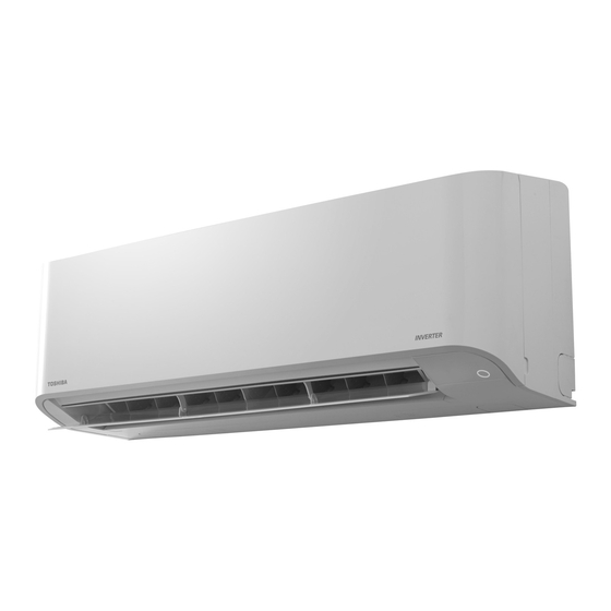
Toshiba RAS-13BKV-E Installation Manual
Hide thumbs
Also See for RAS-13BKV-E:
- Service manual (106 pages) ,
- Installation manual (315 pages) ,
- Owner's manual (84 pages)
Summary of Contents for Toshiba RAS-13BKV-E
-
Page 1: Installation Manual
INSTALLATION MANUAL ENGLISH AIR CONDITIONER (SPLIT TYPE) Indoor unit RAS-07, 10, 13BKV-E Outdoor unit RAS-07, 10, 13BAV-E 11 183 501 98... -
Page 2: Table Of Contents
CONTENTS PRECAUTIONS FOR SAFETY ............................1 ACCESSORY PARTS .................................2 INSTALLATION DIAGRAM OF INDOOR AND OUTDOOR UNITS ...................3 Optional Installation Parts ...............................3 INDOOR UNIT ..................................4 Installation Place ................................4 Cutting a Hole and Mounting Installation Plate .......................4 Piping and Drain Hose Installation ..........................4 Indoor Unit Fixing ................................5 Drainage ..................................5 OUTDOOR UNIT .................................6... -
Page 3: Precautions For Safety
PRECAUTIONS FOR SAFETY PRECAUTIONS FOR SAFETY • Before installation, please read these precautions for safety carefully. • Be sure to follow the precautions provided here to avoid safety risks. The symbols and their meanings are shown below. WARNING : It indicates that incorrect use of this unit may cause severe injury or death. CAUTION : It indicates that incorrect use of this unit may cause personal injury (*1), or property damage (*2). -
Page 4: Accessory Parts
ACCESSORY PARTS ACCESSORY PARTS Indoor Unit Part name Part name Installation Plate × 1 Wireless remote control × 1 Battery × 2 Remote control holder × 1 Mounting screw × 6 Flat head wood screw × 2 Owner’s Manual × 1 Installation Manual ×... -
Page 5: Installation Diagram Of Indoor And Outdoor Units
INSTALLATION DIAGRAM OF INDOOR AND OUTDOOR UNITS INSTALLATION DIAGRAM OF INDOOR AND OUTDOOR UNITS Hook For the rear left and left piping Installation plate Wall Insert the cushion between the indoor unit and wall, and tilt the indoor unit for better operation. -
Page 6: Indoor Unit
INDOOR UNIT INDOOR UNIT When the installation plate is directly mounted Installation Place on the wall • A place which provides the spaces around the indoor unit as shown in the 1. Securely fi t the installation plate onto the wall by screwing it in the upper and diagram lower parts to hook up the indoor unit. -
Page 7: Indoor Unit Fixing
How to remove the drain hose NOTE • The drain hose can be removed by removing the If the pipe is bent incorrectly, the indoor unit may unstably be set on the wall. screw securing the drain hose and then pulling out After passing the connecting pipe through the pipe hole, connect the the drain hose. -
Page 8: Outdoor Unit
2. Put water in the drain pan and make sure that the water is drained out of CAUTION doors. 3. When connecting extension drain hose, insulate the connecting part of Arrange the drain pipe for proper drainage from the unit. extension drain hose with shield pipe. -
Page 9: Evacuating
Packed valve handling precautions Evacuating • Open the valve stem all the way out, but do not try to open it beyond the After the piping has been connected to the indoor unit, you can perform the stopper. air purge together at once. Pipe size of Packed Valve Size of Hexagon wrench AIR PURGE... -
Page 10: Electrical Works
The power supply can be selected to connect to indoor unit or outdoor unit. Choose proper way and connect the power supply and connecting cable by follow the instruction as following. Model RAS-07BKV-E RAS-10BKV-E RAS-13BKV-E Power source 50Hz, 220 – 240 V Single phase Maximum running current 5.0A 6.7A... -
Page 11: Power Supply And Connecting Cable Connection
Power Supply and Connecting Cable Connection Power Supply Input at Indoor Unit Terminal Block (Recommend) Indoor Unit Outdoor Unit Terminal block Power supply cable Stripping length of the power Power supply cable connect to L N supply cable Terminal block (L N 1 2 3) Earth line 50 mm 10 mm... -
Page 12: Power Supply Input Wiring Diagram
Power supply input Wiring Diagram Power supply input at Indoor unit Terminal Block (Recommend) Indoor Terminal Block Power supply input CHASSIS INDOOR UNIT OUTDOOR UNIT Outdoor Terminal Block CHASSIS EARTH Power supply input at Outdoor unit Terminal Block (Optional) Indoor Terminal Block CHASSIS... -
Page 13: Others
OTHERS OTHERS Gas Leak Test Test Operation To switch the TEST RUN (COOL) mode, press [RESET] button for 10 seconds. (The beeper will make a short beep.) Check places for the indoor unit. OPERATION / RESET Button Check places for the outdoor unit. - Page 15 1 1 1 8 3 5 0 1 9 8...


