Samsung nx10 Service Manual
Hide thumbs
Also See for nx10:
- User manual (217 pages) ,
- Manual del usuario (128 pages) ,
- Quick start manual (88 pages)
Table of Contents
Advertisement
Advertisement
Table of Contents

Related Manuals for Samsung nx10


Summary of Contents for Samsung nx10
-
Page 1: Digital Camera
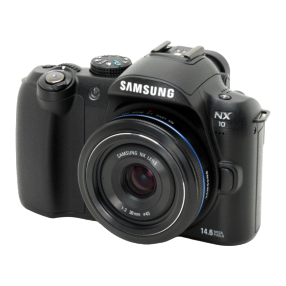
Digital Camera NX10 B Type : NC110... -
Page 2: Table Of Contents
Contents 1. Product Specification 1-1 Specifications ..................1-1 1-2 Instructions on how to use the memory card ........ 1-4 1-3 LCD monitor indicator ............... 1-5 1-4 Camera connections diagram ............1-6 1-5 Identification of features ..............1-7 2. - Page 3 Contents 5-5 Dust reduction (ADJ_02) ..............5-5 5-6 OB, AFE GAIN, ISO Adjustment (ADJ_04) ........5-6 5-7 VFPN, DEFECT PIXEL Adjustment (ADJ_05) ....... 5-7 5-8 AWB Low level adjustment (ADJ_06) ..........5-8 5-9 Internal Strobe, AWB Strobe, AF auxiliary light Test (ADJ_07) .. 5-9 5-10 Proximity sensor Adjustment (ADJ_08) .
-
Page 4: Product Specification
Compensation ±3 EV (1/2EV, 1/3EV step) Eyepoint About 20.2mm AE Lock AEL button Diopter Approx. -4.0 ~ +2.0m ISO Equivalent Auto, 100, 200, 400, 800, Adjustment 1600, 3200 (1EV step) SAMSUNG This Document can not be used without Samsung's authorization... - Page 5 Each 7steps in Amber / Blue adjustment / Green / Magenta axis Picture Modes Standard, Vivid, Portrait, Wizard Landscape, Forest, Retro, Cool, Calm, Classic, Custom (1-3) Parameter Contrast, Sharpness, Saturation, Color tone This Document can not be used without Samsung's authorization SAMSUNG...
- Page 6 ※ These figures are * Specifications are subject to change without prior notice measured under the * All trademarks are the property of their respective owners Samsung standard Direct Printing PictBridge SAMSUNG This Document can not be used without Samsung's authorization...
-
Page 7: Instructions On How To Use The Memory Card
- Check that there is any dust or substance on the memory card contact. - When you use card adaptor, be aware of dust or substance (like a hair) that can be inserted into card adaptor. This Document can not be used without Samsung's authorization SAMSUNG... -
Page 8: Lcd Monitor Indicator
Time, date and year info Shooting option display (right) Focus indicator Drive mode AF zone AF mode Histogram White balance Grid display White balance adjustment Metering option Picture wizard Timer SAMSUNG This Document can not be used without Samsung's authorization... -
Page 9: Camera Connections Diagram
Product Specification 1-4 Camera Connection Diagram SD Memory Card Reader TV Monitor PC (OS: Windows)/ Laptop Computer Mac (OS 9, OS X) Fig. 1-3 Camera Connection Diagram This Document can not be used without Samsung's authorization SAMSUNG... -
Page 10: Identification Of Features
Product Specification 1-5 Identifi cation of features TOP & FRONT Fig. 1-4 Top & Front SAMSUNG This Document can not be used without Samsung's authorization... - Page 11 Product Specification BACK Fig. 1-5 Back This Document can not be used without Samsung's authorization SAMSUNG...
-
Page 12: Operation Instruction & Installation
● Caution ■ It isn’t compatible with Windows XP / Vista / 7 64-bit Editions. ■ Samsung is not responsible for any defects or damages caused by the use of unauthorized computer including an assembled PC. <Table 2-2 For Macintosh>... - Page 13 ■ You can visit the Samsung web-site through the internet. http://www.samsungcamera.com : English http://www.samsungcamera.co.kr : Korean The auto run frame will display. Click the [Samsung Digital Camera Installer] menu in the Auto run frame. Fig. 2-2 This Document can not be used without Samsung's authorization...
- Page 14 Operation Instruction & Installation Install DirectX, Samsung Master by selecting a button shown on the monitor. If a recent version of DirectX has been installed on your computer, DirectX may not be installed. Fig. 2-3 After restarting the computer, connect the PC to the camera with the USB cable.
- Page 15 Install Adobe Reader from the CD provided. If the Internet is not enabled, install Adobe Reader by using the executable file located in the CD. ■ To install the Adobe Reader 6.0.1 correctly, Internet Explorer 5.01 or later has to be installed. Visit “www.microsoft.com” and upgrade the Internet Explorer. This Document can not be used without Samsung's authorization SAMSUNG...
-
Page 16: Faq
• Adjust the exposure value. • Adjust the aperture value or the shutter speed. The photo is too dark • Turn on the fl ash. • Adjust the ISO speed. SAMSUNG This Document can not be used without Samsung's authorization... - Page 17 Depending on your computer environment, the video playback may be intermittent. • Adjust the ISO speed. The wide-angle lens may create distortions on the image. This is the normal feature of the The photo is distorted wide-angle lens. This Document can not be used without Samsung's authorization SAMSUNG...
-
Page 18: Exploded View And Parts List
Exploded View and Parts List 3. Exploded View and Parts List 3-1 TOTAL ASSEMBLY Loc. No Parts No.. Description Q ty Available Remark AD63-03977A COVER HOT SHOE AD67-01399A CAP MOUNT SAMSUNG This Document can not be used without Samsung’s authorization... -
Page 19: Body Assembly
Exploded View and Parts List 3-2 BODY ASSEMBLY 2-18 2-16 2-22 2-11 2-19 2-15 2-11 2-10 2-14 2-17 2-11 2-29 2-20 2-21 2-11 2-12 2-13 2-26 2-23 2-27 2-25 2-28 2-24 This Document can not be used without Samsung's authorization SAMSUNG... - Page 20 SPRING BATTERY COVER 2-26 AD66-00668A LEVER BATTERY COVER LOCK 2-27 AD61-04082A PLATE BATTERY COVER AD97-17794A ASSY-BATTERY COVER COVER BLACK 2-28 AD97-17794B ASSY-BATTERY COVER COVER TITTAN SILVER 2-29 AD07-00117A OLED AM SAMSUNG This Document can not be used without Samsung’s authorization...
-
Page 21: Main Assembly
Exploded View and Parts List 3-3 MAIN ASSEMBLY 3-11 3-10 This Document can not be used without Samsung's authorization SAMSUNG... - Page 22 AD97-17729A ASSY-HOLDER MOUNT 6107-001777 SPRING CMOS ADJUST AD97-17731A ASSY-CMOS 6001-002279 SCREW-MACHINE AD41-01400A FPC_DIGTAL AD41-01401A FPC_ANALOG AD92-01021A MAIN PCB ASSY 6003-001692 SCREW-TAPTYPE 6003-001637 SCREW-TAPTYPE 3-10 6003-00175 SCREW-TAPTYPE 3-11 AD97-17728A MAIN ASSY SAMSUNG This Document can not be used without Samsung’s authorization...
-
Page 23: Mount Holder Assembly
4-19 4-30 4-29 4-35 4-27 4-28 4-18 4-29 4-26 4-29 4-25 4-43 4-38 4-39 4-39 4-37 4-16 4-18 4-11 4-40 4-42 4-36 4-12 4-18 4-16 4-17 4-16 4-15 4-13 4-10 This Document can not be used without Samsung's authorization SAMSUNG... - Page 24 AD63-04413A TAPE MAIN FRAME A 4-29 AD63-04555A CUSHION SHIELD FOAM JACK 4-30 6003-001641 TAPTITE 1.7*3.5 4-31 AD63-04457A SHEET ABSORB A 4-32 AD63-04458A SHEET ABSORB B 4-33 AD63-04592A SHEET ABSORB C SAMSUNG This Document can not be used without Samsung’s authorization...
- Page 25 4-37 AD61-04083A PLATE BOTTOM 4-38 AD61-04141A HOLDER TRIPOD 4-39 6003-001641 TAPTITE 1.7*3.5 4-40 6003-001641 TAPTITE 1.7*3.5 4-41 6003-001647 TAPTITE FH 1.7*4.0 4-42 AD97-17793A ASSY-BOTTOM BASE PLATE CAULKING 4-43 AD97-18500A ASSY-NX-10_CONDENSOR This Document can not be used without Samsung's authorization SAMSUNG...
-
Page 26: Viewfinder Assembly
Exploded View and Parts List 3-5 VIEWFINDER ASSEMBLY 5-11 5-10 5-19 5-13 5-18 5-15 5-17 5-16 5-12 5-20 SAMSUNG This Document can not be used without Samsung’s authorization... - Page 27 5-14 AD63-04196A T/SHEET FINDER WINDOW B 5-15 6031-001688 WASHER B 5-16 AD66-00669A GEAR EP 5-17 6003-001756 SCREW 5-18 AD73-00332A RUBBER EP RING 5-19 AD97-18499A ASSY EVF 5-20 AD97-17732B ASSY-FINDER 3-10 This Document can not be used without Samsung's authorization SAMSUNG...
-
Page 28: Front Cover Assembly
Q ty Available Remark AD63-03954A COVER FRONT AD63-04136A T/SHEET-GRIP SIDE C AD63-04134A T/SHEET-GRIP SIDE A AD63-04135A T/SHEET-GRIP SIDE B AD64-02613A BUTTON-PREVIEW AD97-17736A COVER ASSY-FRONT BLACK AD97-17736B COVER ASSY-FRONT TITTAN SILVER SAMSUNG This Document can not be used without Samsung’s authorization 3-11... -
Page 29: Back Cover Assembly
Exploded View and Parts List 3-7 BACK COVER ASSEMBLY 7-16 7-10 7-11 7-13 7-14 7-15 7-12 7-17 3-12 This Document can not be used without Samsung's authorization SAMSUNG... - Page 30 7-12 AD64-02617A BUTTON PLAY 7-13 AD64-02615A BUTTON-4WAY 7-14 AD64-02616A BUTTON OK 7-15 AD73-00329A RUBBER BUTTON-4WAY 7-16 AD63-04133A T/SHEET-GRIP BACK AD97-17737A COVER ASSY-BACK BLACK 7-17 AD97-17737B COVER ASSY-BACK TITTAN SILVER SAMSUNG This Document can not be used without Samsung’s authorization 3-13...
-
Page 31: Top Cover Assembly
8-10 8-31 8-14 8-26 8-11 8-12 8-28 8-15 8-43 8-37 8-16 8-29 8-38 8-30 8-17 8-18 8-39 8-21 8-19 8-19 8-22 8-19 8-22 8-19 8-45 8-40 8-20 8-40 8-40 3-14 This Document can not be used without Samsung's authorization SAMSUNG... - Page 32 AD61-04087A PLATE-POWER LEVER CLICK 8-29 AD67-01174A CONTACT-POWER LEVER 8-30 6003-001297 SCREW-TAPTYPE 8-31 AD63-04198A T/SHEET-WINDOW AF 8-32 AD64-02606A WINDOW-AF 8-33 6107-001784 SPRING-CS(MODE DIAL) 8-34 AD64-01738A KNOB MODE DIAL -CLICK BALL SAMSUNG This Document can not be used without Samsung’s authorization 3-15...
- Page 33 AD61-04096A PLATE SPRING SHOE 8-45 AD63-04534A CUSHION SHIELD FOAM TOP FPCB 8-46 AD97-17748A ASSY-DIAL MODE 8-47 AD97-17747A ASSY-LEVER POWER AD97-17741A COVER ASSY-TOP-NX-10 BLACK 8-48 AD97-17741B COVER ASSY-TOP-NX-10 TITTAN SILVER 3-16 This Document can not be used without Samsung's authorization SAMSUNG...
-
Page 34: Packing Items
AC CODE CABLE_EXP-D1 AD81-00681A AC CODE CABLE_USA-D1 AD81-00682A AC CODE CABLE_UK-DSC220SE 3903-000348 AC CODE CABLE_AUS-D1 AD43-00192A NX BATTERY(BP1310) AD44-00157A NX CHARGER(BC1310) AD39-00174A USB_CABLE_8PIN AD39-00175A AV CABLE_8PIN AD67-01378A BARREL-HOOD(18-55) AD67-01294A BARREL-HOOD(50-200) SAMSUNG This Document can not be used without Samsung’s authorization 3-17... -
Page 35: Firmware Update
- SD card reader to read and write SD card and PC - Fully charged battery. ► Download the latest NX10 firmware file and save it into the ROOT folder. ► Insert an SD card for firmware into the camera. -
Page 36: Upgrading Procedure By Using C/S Menu
- SD card reader to read and write SD card and PC. - Fully charged battery. ► Download the latest NX10 firmware file and save it into the ROOT folder. ► Insert an SD card for firmware into the camera. - Page 37 Firmware update Fig 4-3 EVC Button 4-way key Fig 4-4 Fig 4-5 Fig 4-6 Fig 4-7 SAMSUNG This Document can not be used without Samsung’s authorization...
-
Page 38: Adjustment
First of all, please un-zip the S/W and install it as below. 1) Please un-zip the attached S/W file on the root of C: 2) Please run the ‘install.bat’ inside the /USB_Filter sub-folder. 3) Please run the ‘_2005vcredist_x86.exe’ inside the /VC++ Patch sub-folder. 4) Please run the NXShutterSpeed.exe program. - To adjust the other sections, please save the each adjustment data to the SD card. The adjustment file name must be “nx10.adj” and save it with info.tg and info.tgw files to root of SD card. SAMSUNG This Document can not be used without Samsung’s authorization... -
Page 39: Tester Mode
(1) OIS lens adjustment. 4. LENS CONTROL (2) ZOOM WIDE SET (2) Fix the wide value of zoom lens. (3) ZOOM TELE SET (3) Fix the tele value of zoom lens. This Document can not be used without Samsung's authorization SAMSUNG... -
Page 40: Cis Tilt Adjustment
■ If you change or disassemble the CMOS ASS’Y, you must do the CMOS Tilt adjustment. <How to Adjust> 1. Prepare CIS Tilt adjustment tools. (Kyoritsu (RSM-5000)) 2. After pressing the Start button, Tilt adjustment procedure finished automatically. 3. After completing the adjustment, please bonding 3 screws and fix it as below. The screw of CMOS Tilt adjustment. Fig. 5-2 <Adjustment Result> It can be adjust below 10 between MOUNT and CMOS ASS’Y. SAMSUNG This Document can not be used without Samsung’s authorization... -
Page 41: Input Cis Dot & Adjust The Shutter Speed (Adj_01)
- (3) LINE PROCESS MARK value is Off. 4. Please run NX-Shutter Speed adjustment program after insert the SD Card which contain the adjustment file. 5. Press the send ( ) button after input CMOS S/N on the Serial section of MAIN PCB. 6. You can find the result of CMOS DOT on the right side as a ( CMOS S/N <NX-Shutter Speed Adjust Program> Fig. 5-4 * If total defects of B, O, T are over 1000, it may display NG. This Document can not be used without Samsung's authorization SAMSUNG... -
Page 42: Dust Reduction (Adj_02)
1. Change the setting on the tester mode as below. - TEST MODE : Left → OK → Right → Ev + OK button at the same time. - 3. Select ADJUSTMENT CONTROL - (2) LINE PROCESS STEP value is 02. - (3) LINE PROCESS MARK value is 01. 2. Insert the SD card to the camera which contained adjustment data. 3. After turning on the camera, it will be start automatically. 4. After completing the adjustment, camera turned off automatically. <Adjustment Result> You can see the adjustment result by using Log File saved on the memory card. You can also confirm the ADJUSTMENT RESULT on the Tester mode. SAMSUNG This Document can not be used without Samsung’s authorization... -
Page 43: Ob, Afe Gain, Iso Adjustment (Adj_04)
- (2) LINE PROCESS STEP value is 04. - (3) LINE PROCESS MARK value is 03. 3. Insert the SD card to the camera which contained adjustment data. 4. After combine the master lens to the camera, attached to the Light Source Box. Light source box Camera Fig. 5-5 5. After turning on the camera, it will be start automatically. 6. After completing the adjustment, camera turned off automatically. <Adjustment Result> You can see the adjustment result by using Log File saved on the memory card. You can also confirm the ADJUSTMENT RESULT on the Tester mode. This Document can not be used without Samsung's authorization SAMSUNG... -
Page 44: Vfpn, Defect Pixel Adjustment (Adj_05)
- TEST MODE : Left → OK → Right → Ev + OK button at the same time. - 3. Select ADJUSTMENT CONTROL. - (2) LINE PROCESS STEP value is 05. - (3) LINE PROCESS MARK value is 04. 3. Insert the SD card to the camera which contained adjustment data. 4. After combine the master lens to the camera, cover the front area of lens by using lens cap or clothes. 5. After turning on the camera, it will be start automatically. 6. After completing the adjustment, camera turned off automatically. <Adjustment Result> You can see the adjustment result by using Log File saved on the memory card. You can also confirm the ADJUSTMENT RESULT on the Tester mode. SAMSUNG This Document can not be used without Samsung’s authorization... -
Page 45: Awb Low Level Adjustment (Adj_06)
- (2) LINE PROCESS STEP value is 06. - (3) LINE PROCESS MARK value is 05. 3. Insert the SD card to the camera which contained adjustment data. 4. After combine the master lens to the camera, attached to the Light Source Box. Light source box Camera Fig. 5-6 5. After turning on the camera, it will be start automatically. 6. After completing the adjustment, camera turned off automatically. <Adjustment Result> You can see the adjustment result by using Log File saved on the memory card. You can also confirm the ADJUSTMENT RESULT on the Tester mode. This Document can not be used without Samsung's authorization SAMSUNG... -
Page 46: Internal Strobe, Awb Strobe, Af Auxiliary Light Test (Adj_07)
3. Change the setting on the tester mode as below. - TEST MODE : Left → OK → Right → Ev + OK button at the same time. - 3. Select ADJUSTMENT CONTROL. - (2) LINE PROCESS STEP value is 07. - (3) LINE PROCESS MARK value is 06. 4. Insert the SD card to the camera which contained adjustment data. 5. After turning on the camera, it will be start automatically. 6. After completing the adjustment, camera turned off automatically. <Adjustment Result> You can see the adjustment result by using Log File saved on the memory card. You can also confirm the ADJUSTMENT RESULT on the Tester mode. SAMSUNG This Document can not be used without Samsung’s authorization... -
Page 47: Proximity Sensor Adjustment (Adj_08)
- (2) LINE PROCESS STEP value is 08. - (3) LINE PROCESS MARK value is 07. 2. Insert the SD card to the camera which contained adjustment data. 3. The distance between eyepiece lens and camera is 4.5cm wall 4.5Cm Camera Tripod Fig. 5-4 4. After turning on the camera, it will be start automatically. 5. After turning on the camera, it will be start automatically. <Adjustment Result> You can see the adjustment result by using Log File saved on the memory card. You can also confirm the ADJUSTMENT RESULT on the Tester mode. 5-10 This Document can not be used without Samsung's authorization SAMSUNG... -
Page 48: Block Diagram
Block Diagram 6. Block Diagram SAMSUNG This Document can not be used without Samsung's authorization... -
Page 49: Pcb Diagrams
TP116 TP37 C300 R276 R424 TP133 FB27 TP65 R143 TP14 PRD_CTL1 TP115 R426 OLED_N4_9V1 GND1 C296 R427 TP94 FB26 TP1TP63 C302C303 R417 BATT_ID_CHK1 R422 R277 C297 TP98 TP92 KA_1_5V1 TP93 SAMSUNG This Document can not be used without Samsung’s authorization... -
Page 50: Main Pcb (Bottom)
FB21 C155 C154 C151 FB19 C135 C243 C106 BAT1 C229 C250 C221 C234 C293 C96C95 R683 C290 C294 R105 C237 C291 R113 C292 R112 R104 R114 R102 E5E6 C235 C236 This Document can not be used without Samsung's authorization SAMSUNG... -
Page 51: Key Pcb
PCB Diagrams 7-3 Key PCB SAMSUNG This Document can not be used without Samsung’s authorization... -
Page 52: Strobo Pcb
PCB Diagrams 7-4 Strobo PCB This Document can not be used without Samsung's authorization SAMSUNG... -
Page 53: Lens Pcb
PCB Diagrams 7-5 Lens PCB SIO3_MISO SAMSUNG This Document can not be used without Samsung’s authorization... -
Page 54: Trig Pcb
PCB Diagrams 7-6 Trig PCB This Document can not be used without Samsung's authorization SAMSUNG... -
Page 55: Top Hotshone Pcb
PCB Diagrams 7-7 Top Hotshone PCB SAMSUNG This Document can not be used without Samsung’s authorization... -
Page 56: Condenser Pcb
PCB Diagrams 7-8 Condenser PCB HOLE1 HOLE2 This Document can not be used without Samsung's authorization SAMSUNG... -
Page 57: Cis Pcb
PCB Diagrams 7-9 Cis PCB SAMSUNG This Document can not be used without Samsung’s authorization... -
Page 58: Pv Pcb
PCB Diagrams 7-10 PV PCB 7-10 This Document can not be used without Samsung's authorization SAMSUNG... -
Page 59: Disassembly And Reassembly
Always use the anti-static mat and wrist band, as the parts can be damaged from static electricity PCB Type from the hand. CONTACT Type Be careful of damage of deformation of parts from the pin set. SAMSUNG This Document can not be used without Samsung’s authorization... - Page 60 Disassembly and Reassembly Disassembly image Disassembly description Remove 2 Screws. Remove 3 Screws. Remove 7 Screws. This Document can not be used without Samsung's authorization SAMSUNG...
- Page 61 Disassembly and Reassembly Disassembly image Disassembly description Remove 2 Screws. Disassemble the EP CAP. Remove 2 Screws. SAMSUNG This Document can not be used without Samsung’s authorization...
- Page 62 Disassembly and Reassembly Disassembly image Disassembly description Disassemble the Holder EP Cap. Remove 1 Screw. Disassemble the Back Cover Assy. This Document can not be used without Samsung's authorization SAMSUNG...
- Page 63 Disassembly and Reassembly Disassembly image Disassembly description Disassemble the Jack Cover Assy. Disassemble the Battery Cover Assy. Disassemble the Front Cover Assy. SAMSUNG This Document can not be used without Samsung’s authorization...
- Page 64 Disassembly and Reassembly Disassembly image Disassembly description Caution It must be processed for discharge to the main condens- er as shown in the below picture. Disassemble the LCD Assy. Remove 3 Screws. This Document can not be used without Samsung's authorization SAMSUNG...
- Page 65 Disassembly and Reassembly Disassembly image Disassembly description Disassemble the LCD Holder. Disassemble the Connector in Main PCB. Disassemble the Lead wire in Strobe PCB. SAMSUNG This Document can not be used without Samsung’s authorization...
- Page 66 Disassembly and Reassembly Disassembly image Disassembly description Remove 1 Screw. Disassemble the Top Cover Assy. Disassemble the Connector in Main PCB. This Document can not be used without Samsung's authorization SAMSUNG...
- Page 67 Disassembly and Reassembly Disassembly image Disassembly description Remove 2 Screws. Disassemble the Finder Assy. Remove 2 Screws, 2 Connectors, 6 Lead Wire in Main PCB SAMSUNG This Document can not be used without Samsung’s authorization...
- Page 68 Disassembly and Reassembly Disassembly image Disassembly description Disassemble the Main PCB. Remove 5Screws. Disassemble the Bottom Plate. 8-10 This Document can not be used without Samsung's authorization SAMSUNG...
- Page 69 Disassembly and Reassembly Disassembly image Disassembly description Disassemble 1 Screw, soldering. Remove 2Screws. Disassemble the Battery Chamber Assy. SAMSUNG This Document can not be used without Samsung’s authorization 8-11...
- Page 70 Disassembly and Reassembly Disassembly image Disassembly description Remove the 2Lead Wire. Remove 3Screws. Disassemble the CMOS Base Plate Assy. 8-12 This Document can not be used without Samsung's authorization SAMSUNG...
- Page 71 Disassembly and Reassembly Disassembly image Disassembly description Remove 2Screws. Disassemble the Shutter Assy. Remove 2Screws in Strobe PCB Assy. SAMSUNG This Document can not be used without Samsung’s authorization 8-13...
- Page 72 Disassembly and Reassembly Disassembly image Disassembly description Disassemble the Strobe PCB Assy. 8-14 This Document can not be used without Samsung's authorization SAMSUNG...
- Page 73 © SAMSUNG Co.,Ltd Printed in Korea EC-NX10 6060d1263668503...