Instantel Micromate Owner's Manual
Vibration and overpressure monitor, 4-channel unit seismograph
Hide thumbs
Also See for Micromate:
- Release notes (22 pages) ,
- Technical note (9 pages) ,
- Instruction sheet (4 pages)
Table of Contents
Advertisement
Quick Links
Advertisement
Table of Contents

Related Manuals for Instantel Micromate


Summary of Contents for Instantel Micromate
- Page 2 (no PC required) or automatically transferred from the unit in a remote location with a modem back to the computer in your office. The Micromate is built to last. The main unit comes with a fully sealed top panel. The non- corrosive fully sealed industrial grade connectors are labeled and color coded for easy identification and installation.
-
Page 3: Instantel
While full featured, we feel our units also represent the best available value in the industry. Instantel works closely with local and global suppliers and our own Teams to ensure products are in stock and available when you need them. We strive to provide the best and most responsive technical support in the industry. -
Page 4: Warranty
ARNING This is a CE Class B product that has been tested to and passed the IEC 61010-1 (CB test report available from Instantel). If this product is not used as outlined within this manual, it may cause radio interference. -
Page 5: Table Of Contents
6. Micromate Protective Boot ..............15 6.1. Attaching the Boot to the Micromate ..............15 6.2. Installing the Micromate in a Remote Station ............16 6.3. Round and Irregular Surface Installation ..............18 7. Dust Caps and Connectors ............... 19 7.1. - Page 6 11.1.7. Trigger Level ..................62 11.1.8. Location ....................67 11.1.9. Client ..................... 68 11.1.10. Company ....................68 11.1.11. General Notes..................69 11.1.12. Job Number ..................69 11.1.13. Scheduler ..................... 70 11.1.14. Scaled Distance ..................71 Micromate Operator Manual – 721U0201 Revision 6...
- Page 7 Supported USB Devices ............104 13.1. USB Memory Stick ....................104 13.2. Modems ......................... 105 13.3. Micromate Portable Field Printer ................106 13.3.1. Sample Waveform Printout ..............107 Sample Waveform Printout - Continued ............108 13.3.2. Sample Histogram Printout ..............109 Sample Histogram Printout - Continued ............
- Page 8 14.4.1. Soft Material Installations ..............117 Calibration ................. 120 15.1.1. Geophone Calibration ................. 120 15.1.2. Microphone Calibration ..............122 15.1.3. Micromate Sensor Check Feature ............123 Maintenance ................124 Waste Management Directive ..........125 Troubleshooting ............... 126 Appendix ................... 128 19.1.
-
Page 9: Before You Begin
To qualify for these benefits you must complete the registration card included with your Micromate and return it to Instantel by mail, email or facsimile within ten (10) days of purchasing your new monitor. You may also register your product online at: http://www.instantel.com/servicecalibration/warranty.aspx... -
Page 10: Handling Precautions
Never force a connector. Ensure you are attaching the cable or device to the proper connector. The Micromate is water-resistant. Do not immerse in water. Clean with a damp cloth. 1.5. Micromate ISEE and DIN Models... - Page 11 Micromate DIN Model Refer to section 15.1.1 Geophone Calibration for additional information on the ISEE and DIN standards. Micromate Operator Manual – 721U0201 Revision 6...
-
Page 12: Quick Start Instruction Label
2. Q UICK TART NSTRUCTION ABEL The Micromate Quick Start Instruction label is found on the back of the Micromate unit. Micromate Operator Manual – 721U0201 Revision 6... -
Page 13: Basic Tutorial
In this Basic Tutorial, you will connect the geophone and microphone and configure your Micromate to create a sample Event using the Waveform record mode. Then once the event has been recorded you will review the results on the Micromate’s touch screen display. - Page 14 Initialization Screen with Progress Bar Home Screen NOTE: If the battery is low connect the Micromate to AC power with the supplied charger. Step 3: Review/Modify the Current Setup 1) Press the Setup key then select the View/Edit Current Setup menu.
- Page 15 2) Run Sensor Check: Press the sensor check button on the key pad or touch the sensor check icon on the touch screen. The Micromate will now confirm that sensors are ready for monitoring by displaying a message indicating that sensors have “passed” as shown below.
- Page 16 In all of the above cases, ensure that the geophone is properly installed and is level. NOTE: A failed sensor check condition should be corrected prior to initiation of monitoring. Monitoring in a failed sensor check state could result in inaccurate data being recorded on the failed channel. Micromate Operator Manual – 721U0201 Revision 6...
- Page 17 1) Press the Start Monitor key or the Start Monitor icon. 2) Once the Micromate is monitoring, conduct a test by shaking the geophone to trigger the unit and record an event. This will confirm that the system is operational.
- Page 18 Printer icon will print the event on the external printer. 2) Double tap the Event entry or press the Right Arrow key to open the event and display the event summary results. Waveform Summary Micromate Operator Manual – 721U0201 Revision 6...
- Page 19 6) Press the Cancel icon or Cancel key to Exit the Event List and return to the Ready to Monitor screen. 7) To transfer events to your PC for storage and further analysis, please refer to the Blastware User manual. CONGRATULATIONS, you are now a Micromate user! Micromate Operator Manual – 721U0201 Revision 6...
-
Page 20: Features And Benefits
EATURES AND ENEFITS USB Connectivity: The Micromate provides two USB ports. One USB port is dedicated for downloading events to the PC while the other port is used to connect external devices such as powered USB Hubs, Modems, Memory sticks, Printers or a GPS. - Page 21 Micromate unit. Optional Auxiliary I/O Connector: This factory installed option allows for the connection and operation of the Instantel Remote Alarm and or External Trigger Cable. Optional Remote Alarm: The Remote Alarm allows the Micromate to control two external devices such as sounder or strobe lights.
-
Page 22: Range Of Applications
PPLICATIONS Instantel vibration and overpressure monitors are among the most versatile seismographs available in the world today. From the simplest to the most demanding applications, Instantel’s Micromate instruments offer innovative features and a variety of recording formats that increase their functionality and allow for flexibility across a wide variety of applications. -
Page 23: Micromate Protective Boot
Micromate, refer to Section 19.6 Torque Specifications and Guidelines. 1) Insert the Micromate unit into the boot with the top on the unit in the direction of the arrows in the boot. Micromate Operator Manual – 721U0201 Revision 6... -
Page 24: Installing The Micromate In A Remote Station
The boot can be secured to the back plate of the remote station before the Micromate unit is inserted into the boot. This will make your remote station quicker to install, reduce down time for routine tasks, like annual calibration, by allowing units to removed and reinstalled much quicker. - Page 25 3) Secure the individual parts, the Modem and Micromate protective boot in this example, to the mounting surface. Modem and Protective Boot Secured 4) Install the Micromate into the protective boot. Install the Micromate in the Protective Boot 5) Install the mounting panel in the enclosure.
-
Page 26: Round And Irregular Surface Installation
6.3. Round and Irregular Surface Installation When it is not possible or convenient to use screws to secure the Micromate in place, the protective boot can be held in place with large plastic tie-wraps or metal straps. The slots in the bottom of the boot provide space for these straps while not interfering with the installation of the unit. -
Page 27: Dust Caps And Connectors
However, if one of the dust caps were to be damaged it can be easily replaced without opening the Micromate unit. Remove the three screws, the hold down bar and the damaged dust cap from the Micromate. Position the new dust cap on the connectors, replace the hold down bar and three screws. -
Page 28: Geophone, Microphone And Auxiliary Connectors
Protective Dust Caps without Dust Caps Pulled Back to Access Connectors Optional AUX Connector If the Micromate has been factory configured with auxiliary I/O option the AUX connector and AUX dust cap will also have been installed. Protective Dust Caps With... -
Page 29: Keypad
8.1. Power Button The Power button has two different functions: 1) The power button is used to turn the Micromate on and off by electrically connecting and disconnecting the internal battery. This eliminates the need to open the unit. 2) The power button is also used to turn the display on and off. When the display has been turned off the Micromate will be placed in a low power state to conserve battery life. - Page 30 AC power source with the supplied charger. Refer to section 12.1 Charging the Battery for additional information. If the Micromate is to be stored for an extended period of time or shipped with a commercial carrier it must be turned off by disconnecting the internal battery. To turn the Micromate off press and hold the power button for at least five seconds.
-
Page 31: Turn The Micromate Display On Or Off
Disconnect the Battery or Cancel NOTE: The Micromate cannot be turned off if it is in monitor mode or if the scheduler function is running. If the unit is in either of these modes and the power button is held down for more than three second, a message will be displayed indicating the battery cannot be disconnected while monitoring. -
Page 32: Sensor Check Button
Pressing the Sensor Check button will send a pulse or series of pulses to the geophone and microphone while the Micromate monitors their response. This allows the Micromate to ensure the geophone and microphone are connected and that the geophone is level. The results of the sensor check will be presented on the display. -
Page 33: Setup Button
Failing Microphone Sensor Check 8.3. Setup Button The Setup button will allow the user to access the five different setup menus in the Micromate program. These menus are used to configure how the Micromate will monitor and record data as well as perform routine maintenance. -
Page 34: Heartbeat Indicator Led
They are used to move throughout the different menus in the direction of the arrow. In addition to navigation: 1) If the Micromate is in monitor mode or on the home screen, the down arrow is used as a short cut to list the events stored on the unit. -
Page 35: Touch Screen Display
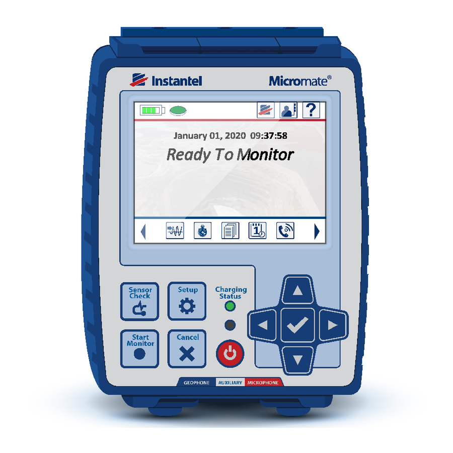
CREEN ISPLAY The Micromate has a color touch screen display used for configuring the unit and displaying the event results. The screen functionality has been divided into three Sections (see the picture below). The icons in Section #1 are context sensitive and will change depending on the currently open screen. -
Page 36: Battery Icon
The Battery icon is located in the top left corner of the display and will change as the battery charge level changes. If the Micromate is not connected to an external power source the battery icon will decrease in 25% increments as the battery is depleted. The actual battery status can be displayed by touching the battery icon. - Page 37 Depleted message, exit monitor mode if applicable and start a 30 second countdown timer. Battery Depleted – 30 Seconds to Shutdown If the Micromate is not connected to an external power source within this 30 second countdown, the unit will automatically shut down and disconnect the internal battery. To continue, connect the external power source and turn the Micromate on by pressing and holding the Power button for five seconds.
-
Page 38: Memory Icon
Sample Memory Status a. Memory Capacity The Micromate can store a maximum of 1000 events in its 15 Megabytes (MBs) of storage memory. An event is defined as a four channel one second waveform event that has been recorded at a sample rate of 2048 S/s. -
Page 39: Cancel Icon
9.1.3. Cancel Icon The Cancel icon is located in the top right corner of all of the Micromate windows except when in the home screen, as the home screen is the only one that cannot be closed. It is used to close the current window, exit the current window and return to the previous window or to discard any changes that have been made in the current window. -
Page 40: Help Icon
The Owner Information icon, available on the home screen, will display the owner details that have been downloaded into the Micromate from the Blastware program. This owner information can be customized to your requirements. This information cannot be edited on the Micromate. Refer to the Blastware Operators manual for instructions on loading or editing the owner information on the Micromate. -
Page 41: Instantel Information
The GPS (Global Positioning System) icon will appear when a Magellan GPS eXplorist 310 has been connected to the USB port of the Micromate and the Micromate is in the GPS Location or Set System Time and UTC Offset menu. The GPS Location menu can be used to download GPS coordinates (waypoints) of the vibration source and the location of the sensor into the Micromate. -
Page 42: Add Operator Icon
NOTE: Deleting an item will permanently remove it from the unit. Setup File Select Operator Micromate Operator Manual – 721U0201 Revision 6... -
Page 43: Save Icon
Note Printing is only supported when the Micromate is configured for the English language. For other languages, use a memory stick to copy and transfer the events or connect the Micromate to the computer directly to print reports using Instantel’s computer software. -
Page 44: Main Display
When editing numbers, use the Up and Down arrow keys or use a finger to swipe up and down in the highlighted box. To select a different item, use the Left and Right arrow keys or simply touch the desired entry. Section #2 Main display area Micromate Operator Manual – 721U0201 Revision 6... -
Page 45: Short Cut Icons
Micromate’s operating system. These icons are located at the bottom of the display and can be used at any time except when the Micromate is in monitor mode or if an information window, such as help or battery status is displayed. The arrows at the left and right of these short cuts are used to display additional short cut icons. - Page 46 If an event was selected by mistake, use the navigation keys to highlight the event and press the check mark key or use a finger to touch and deselect the event. Micromate Operator Manual – 721U0201 Revision 6...
- Page 47 Refer to the manufactures instructions and your Windows manual for more information on the FAT system. While viewing the list of events insert the USB memory stick into the Micromate’s USB port as shown below. The Micromate will automatically detect the presence of the memory stick and display the save icon.
- Page 48 Copying Completed Press Check Mark Selecting Copy All Events & Log will copy all of the events that have been stored on the Micromate as well as the monitor log file. A message confirming the selection will be displayed. Pressing the check mark key or touching the check mark on the screen will start the copying of the events.
- Page 49 Note Printing is only supported when the Micromate is configured for the English language. For other languages, use a memory stick to copy and transfer the events or connect the Micromate to the computer directly to print reports using Instantel’s computer software.
- Page 50 4) Connect the free end of the printer cable to the Micromate’s USB port. Printer Connected to the Micromate 5) The Micromate will automatically detect the presence of the printer and display the printer icon. If the printer is not recognized remove the cable, make sure the printer is the correct model, make sure the printer has been powered on and reconnect the cable ensuring it is properly connected to the printer and to the Micromate.
- Page 51 Print Status Printing Completed Selecting Print All Events will print all of the events that have been stored on the Micromate. A message confirming the selection will be displayed. Pressing the check mark key or touching the check mark on the screen will start printing the events. A status window will be displayed showing the progress of the overall print process.
- Page 52 Selecting Delete All Events & Log will delete all of the events and log files that have been stored on the Micromate. A message confirming the selection will be displayed. Pressing the check mark key or touching the check mark on the screen will start the deletion of the events. A status window will be displayed showing the progress of the overall deletion process.
-
Page 53: Edit Time
The Maintenance short cut will take you directly to the maintenance menu. The maintenance menu has a list of functions that can be used to view specific information about the Micromate unit. Refer to section 11.5 Maintenance Menu for additional information. -
Page 54: Password
Password for additional information. 9.3.9. Setup The Setups short cut will allow the user to access the five different setup menus in the Micromate program. These menus are used to configure how the Micromate will monitor and record data as well as perform routine maintenance. -
Page 55: Arrow
The Instantel website also contains a list of authorized dealers and calibration sites around the world. Refer to section 9.1.7 Instantel Information for additional information. 9.3.15. Arrow The Arrows at each end of the short cut icon tool bar are used to display additional short cut icons. -
Page 56: Entering Information
Entering this data can be done using the Micromate keypad, touch screen or a combination of both. The currently active menu or data will be highlighted. To select a different item use the navigation keys to move up, down, left or right to the desired item or simply touch the item. - Page 57 Rename Setup File or Save to New File, do not allow the use of Special Characters, other than underscore, space and dash (–, , _ ). The unit will not respond to attempts of entering these characters. Micromate Operator Manual – 721U0201 Revision 6...
-
Page 58: Menu Structure
11. M TRUCTURE The Micromate menu structure has been divided into five separate setup menus to group the related information and functions together. To access these five setup menus press the Setup key or Setup icon on the Micromate unit. The five setup menus are:... - Page 59 Setup Menus Micromate Operator Manual – 721U0201 Revision 6...
- Page 60 Micromate Operator Manual – 721U0201 Revision 6...
-
Page 61: View/Edit Current Setup
The Micromate can be set to trigger at a specific level before it will record data or data can be recorded as soon as it enters monitor mode. The data can be recorded in two formats; waveform and histogram. -
Page 62: Microphone Type
Once one of these signals exceeds the preset trigger level the Micromate will start recording the data. Data will continue to be saved until the preset number of seconds of data has been recorded. The event will then be closed and the peak vibration and overpressure as well as the zero crossing frequencies will be written to the display while the Micromate goes back into monitor mode. - Page 63 “√” (check mark) to be pressed to start recording data. The Micromate will continue recording data until the “√” is pressed a second time stopping the recording. This mode can be used to record event data when triggering automatically at a specific level may not be practical or even possible.
- Page 64 2048 samples of each channel as the peak for each interval. As each interval is completed the peak vibration, overpressure and associated zero crossing frequencies are saved to the file and written to the display. This will continue until the Micromate exits monitor mode.
- Page 65 While monitoring in histogram mode, if one of the input signals exceeds the preset trigger level the Micromate will save all of the data samples for the preset record time in order to be able to reproduce a waveform graph of the event. The histogram will continue to run and save the interval data.
- Page 66 The Micromate will continue to record histogram and waveform data until the internal memory is full, the battery becomes depleted or the user exits monitor mode. This mode should be used for long term monitoring projects where the background and peak vibration and overpressure results are required.
- Page 67 Histogram Event Waveform Event Micromate Operator Manual – 721U0201 Revision 6...
-
Page 68: Interval Length
11.1.4. Interval Length The Interval Length is the amount of time the Micromate will sample the incoming signals before saving the highest level and associated zero crossing frequency found for each channel. The interval length can be set from two to 30 seconds in one second increments and then from 30 seconds to 30 minutes in 30 seconds increments. - Page 69 A rule of thumb for blast monitoring is to set the record time equal to the length of the blast plus one second for every 300 meters (1000 feet) of distance the Micromate is away from the blast, all rounded up to the next highest second. If a blast was 0.5 seconds long and the Micromate was located 600 meters away the record time should be set to 3 seconds (0.5 seconds +...
-
Page 70: Sample Rate
11.1.6. Sample Rate This is the number of samples the Micromate will read from the analog to digital (A/D) converter each second while it is in monitor mode. The higher the sample rate the better the resolution when reproducing the waveform. However, as the sample rate increases so does the size of the event file. - Page 71 (in/s). Geophone Trigger Level Set to 12.7 mm/s Microphone Trigger: This can be set to Enabled or Disabled. If it is enabled the Micromate will monitor the microphone sensor level and start recording data if this level exceeds the preset trigger level.
- Page 72 When using the Sound Level Microphone, the following additional options are available on the Trigger Level page: Response Time Frequency Weighting LN1 LN2 Sound Level Mic Trigger Level Options Micromate Operator Manual – 721U0201 Revision 6...
- Page 73 Frequency weightings are electronic filters that adjust the way the Sound Level Microphone measures noise. The Micromate Sound Level Microphone gives you the choice between A- weighting and C-weighting. Both weightings cover the full frequency range of 20 Hz to 20 kHz. A- weighting approximates the frequency sensitivity of the human ear.
- Page 74 Statistical noise levels are useful parameters when sampling fluctuating noise, showing what samples are above specific levels. The Micromate Sound Level Microphone lets the user set two different statistical noise levels, LN1 and LN2. LN1 and LN2 values are percentages, meaning that if LN1 is set to 10%, a line will be drawn across the resulting graph at the level where 10% of the samples exceed the value of the line.
-
Page 75: Location
This will display a new window with a full QWERTY keyboard and allow the entry of up to 40 alpha numeric characters to represent the location of the Micromate. Pressing the shift key ( ) will toggle the keyboard between upper and lower case letters. The location could be a specific street address or a more general location such as a city. -
Page 76: Client
The company name could be your company or the company you are working for. Once the information has been entered press the Enter key on the keyboard to save the information. Specific Company Name Micromate Operator Manual – 721U0201 Revision 6... -
Page 77: General Notes
The job number can be set to any value between 1 and 9999. The Job Number can help keep track of events stored in the Micromate or in the Event Manager of the Blastware program. -
Page 78: Scheduler
For example, if the Micromate is in monitor mode with the scheduler enabled and the time to start monitoring is still in the future the Scheduler Running message will be displayed. Once the start monitor time has been reached the programmed monitoring mode will be displayed. -
Page 79: Scaled Distance
It is calculated by dividing the Distance From Blast by the square root of the Charge Weight. Scaled Distance Summary Screen Micromate Operator Manual – 721U0201 Revision 6... -
Page 80: Gps Location
GPS device to the Micromate and downloading the information or by manually entering the new waypoints into the Micromate. A GPS device can be used to locate your exact latitude and longitude position based on orbiting satellites. Once the waypoints have been entered into the Micromate, the distance between these two points will be calculated. - Page 81 Make sure the Micromate has been turned on and is in the GPS Location menu. e. Connect the GPS to the Micromate’s USB port using the cable that was supplied with the GPS device.
-
Page 82: Auxiliary I/O (Optional)
If you do not have a compatible GPS device and still wish to use the GPS Location function, the Micromate has been designed to accommodate the manual entry of the waypoint values. Select the coordinate to be edited by touching the value on the display or using the navigation keys and pressing the check mark key. - Page 83 External Trigger Remote Alarm b. Auxiliary I/O Off With the Auxiliary I/O set in the Off state the Micromate will not monitor the input signal nor will it drive the output signals. c. External Trigger When the auxiliary I/O has been configured for an External Trigger, the Micromate will monitor the input signal from the External Trigger Cable (part No.
- Page 84 Refer to the appendix 19.3 External Trigger Cable for additional information. d. Remote Alarm When the Auxiliary I/O has been configured as a Remote Alarm the Micromate will drive two separate output contacts. These two outputs are called Warning and Alarm outputs. The warning output is enabled when the Micromate exceeds the pre-set trigger level and the alarm output is enabled when the Micromate exceeds the pre-set alarm level.
- Page 85 Alarm On menu to display a new window allowing the selection of the geophone and/or microphone as the alarm trigger source and setting the level to trigger the alarm. Sample Alarm Source and Alarm Level Micromate Operator Manual – 721U0201 Revision 6...
-
Page 86: Saving A Setup File
These changes can be saved to the current setup file or saved as a new file. The Micromate can store up to 25 different setup files to make switching the configuration of the Micromate quick and easy. -
Page 87: Select Setup File
Enter key. 11.2. Select Setup File The Micromate can store up to 25 different setup files. This allows the Micromate to be configured to different job specifications very quickly. It can also prevent having to re-enter information when the unit is deployed in a location that was previously monitored. -
Page 88: Select Current Setup File
Current List of Setup Files Within the setup file list the asterisk (*) is used to indicate the current setup file that will be used when the Micromate is placed into monitor mode. 11.2.1. Select Current Setup File To select a different file, use the arrow keys to navigate to the entry and press the check mark key or double tap on the desired file name. -
Page 89: Delete Setup File
11.2.3. Delete Setup File If one of the setup files is no longer required it can be deleted from the Micromate. Navigate to the entry to be deleted using the keyboard or the touch screen and press the delete icon. This will display a message confirming this entry is to be deleted. -
Page 90: Set Current Operator
List or Operator Names Within the list of operator names the asterisk (*) is used to indicate the current name that will be included with the recorded events when the Micromate is placed into monitor mode. 11.3.1. Set Current Operator To select a different name, navigate to the desired entry and press the check mark key or double tap on the desired name. -
Page 91: Add New Operator Name
11.3.4. Delete Operator Name If one of the operator names is no longer required it can be deleted from the Micromate. Navigate to the entry to be deleted using the keyboard or the touch screen and press the trash can icon. This will display a message confirming this entry is to be deleted. -
Page 92: Sensor Check
The options are disabled, before the event or after the event. a. Sensor Check Disabled If the sensor check has been disabled the Micromate will not perform the test on the geophone or microphone and the event report will indicate that the sensor check has been disabled. - Page 93 Sensor Check After Event When the sensor check is set to occur after the event, the Micromate will perform a new sensor check after each event that is recorded while in monitor mode. Each new sensor check will be attached to the event that has just been completed.
-
Page 94: Measurement Units
Auto Call Home Screen Setting the Session Time Out The modem can be set to generic or USB to PC. If this is set to generic the Micromate will assume it is connected to a modem and communicate through the USB port ( ). - Page 95 USB-to-Serial cable will be disabled when the Micromate is in a monitoring state. Micromate Operator Manual – 721U0201 Revision 6...
- Page 96 The modem baud rate is used to set the speed at which the data will be transmitted from the Micromate to the modem. The options for the baud rate are 9600, 19200, 38400, 57600, 115200 and 230400 bits per second (bps). This baud rate must match the baud rate set on the modem.
- Page 97 Transferring Event b. Stop Monitoring and Call Home With Auto Call Home configured to stop monitoring and call home, the Micromate will respond differently depending on the monitoring mode. 1) With the Micromate in waveform or histogram combo mode, the Micromate will pause monitoring, complete the histogram event, if applicable, connect to the modem and transfer the waveform and histogram event data back to the remote computer.
-
Page 98: Set System Time And Utc Offset
2) If the Micromate is in histogram only mode the event data will only be transferred once the histogram event has been completed. Too manually exit and complete a histogram event press the cancel icon or cancel key. Histogram event can also be closed automatically through the preconfigured scheduler. - Page 99 To synchronize these values to the GPS system, connect the supported GPS device to the Micromate’s USB port and press the GPS icon. This will prompt you to confirm that you want to synchronize the Micromate to the GPS. Once the values have been set, pressing the save icon will save the changes and update the display.
-
Page 100: Display And Sound
Beep on Key Press The Micromate can be set to beep every time a key is pressed or to not beep when a key is pressed. When set to beep on a key press, the Micromate will provide an audible response in addition to the tactile response of the key itself. -
Page 101: Password
The default setting is English. f. Long Text Scrolling Long text scrolling controls the display of long text on the Micromate screen. When long text scrolling is on, text too long to be displayed is scrolled across the screen. The default setting is Off. -
Page 102: Restore Factory Defaults
Current Password Password Cleared In the event a password has been entered and forgotten, the Micromate has been programmed with the default password {3102}. This six character password will override the current password. 11.4.8. Restore Factory Defaults The Restore Factory Defaults function will reset the current setup file to those originally set by Instantel at the factory. -
Page 103: Owner Information
Sample Owner Information 11.4.10. Instantel Information The Instantel Information icon will displays the Instantel website address. For easy access from a smart phone with a QR Code application, use the QR Code to immediately direct and display the Instantel.com website. The Instantel website also contains a list of authorized dealers and calibration sites around the world. -
Page 104: Maintenance Menu
Full Maintenance Menu 11.5.1. About The About menu will display some of the basic information about the Micromate unit. The first line is the model (ISEE or DIN) and options that have been installed, followed by the serial number, software release version, the calibration date, available memory and the battery level. -
Page 105: View Channel Data
If the absolute average value is greater than five counts without any vibration or overpressure, it is recommended that the Remove Offset command be performed. Sample of Data being Read Micromate Operator Manual – 721U0201 Revision 6... -
Page 106: View Battery Data
11.5.4. Self Check The Self Check menu will perform a verity of internal test on the Micromate unit. The results of some of these tests will be presented on the display. This function is used as a diagnostic tool that may be requested to assist in technical support of the product. -
Page 107: Disconnect Batteries
The Disconnect Battery function will electrically disconnect the battery from the unit. If the Micromate is to be stored for a long period of time, make sure the battery is fully charged and then perform this command. To avoid accidentally disconnecting the battery you will be asked to confirm the disconnect battery operation. -
Page 108: Calibrate Sound Level Microphone
The calibration date is set to the current date, and the name of the calibrator is set to “Field Calibration”, which will appear on event reports. In order to use Calibrate Sound Level Microphone, Instantel recommends the following sound level microphone calibrators: Delta OHM HD9101 Class 1 ... -
Page 109: Battery Overview
Instantel repair facility should they need to be replaced. The Micromate has a tamper label located on the side of the case to prevent it from being opened. Any attempt to service this product will void any and all warranties offered by Instantel. -
Page 110: Extreme Temperature Operation
0° C (32° F). To prevent damage to the internal lithium ion battery, the Micromate will only charge the internal battery if the ambient temperature is between 0° C and 45° C (32° F and 113° F). This will NOT prevent the Micromate from operating across its entire operating temperature range of -40 to +45°... -
Page 111: Battery Shipping Instructions
113° F) the Micromate will automatically start charging the internal battery. 12.3. Battery Shipping Instructions Prior to shipping the unit to Instantel or an Authorized Service and Calibration Facility, the battery must be disconnected. This can be done by pressing and holding the power button for five seconds and confirming that you do want to disconnect the battery. -
Page 112: Supported Usb Devices
The Micromate allows you to save event data and the monitor log files directly to a USB memory stick. This avoids the need to transport a laptop to the field for downloading the event data. The memory stick can later be inserted into a computer and accessed through the Blastware program. -
Page 113: Modems
13.2. Modems The Micromate supports the AirLink Raven X, GX400 and LS300 modems and requires a static IP address. These modems are not available from Instantel and must be purchased through a third party provider. The modem requires a USB to RS-232 adaptor cable that is available from Instantel or online (Instantel Part No. -
Page 114: Micromate Portable Field Printer
Note Printing is only supported when the Micromate is configured for the English language. For other languages, use a memory stick to copy and transfer the events or connect the Micromate to the computer directly to print reports using Instantel’s computer software. -
Page 115: Sample Waveform Printout
Sample Waveform Printout 13.3.1. Micromate Model - ISEE Event Setup Information Event Summary Information Waveform Graph (Printout continued on next page) Micromate Operator Manual – 721U0201 Revision 6... -
Page 116: Sample Waveform Printout - Continued
Sample Waveform Printout - Continued Compliance Graph Sensor Check Results Calibration Company and Date Micromate Operator Manual – 721U0201 Revision 6... -
Page 117: Sample Histogram Printout
13.3.2. Sample Histogram Printout Micromate Model - ISEE Event Setup Information Event Summary Information Histogram Graph Micromate Operator Manual – 721U0201 Revision 6... -
Page 118: Sample Histogram Printout - Continued
(Printout continued on next page) Sample Histogram Printout - Continued Sensor Check Results Calibration Company and Date Micromate Operator Manual – 721U0201 Revision 6... -
Page 119: Gps - Global Positioning System
Refer to section 11.1.14 Scaled Distance for additional information. The GPS can also be used to synchronize the real time clocks on multiple Micromate units. Refer to section 11.4.5 Set System Time and UTC Offset for additional information. -
Page 120: Powered Usb Hubs
Connect the hub to the Micromate’s USB port and a maximum of two memory sticks at the same time. While in the event list, if events are saved to the memory stick, an extra message will be presented and the desired memory stick must be selected. -
Page 121: Installing The Geophone And Microphone
The geophone is used to detect ground vibrations and then transmit related vibration data to the Micromate unit, via a cable. If the geophone sensor is not located in close proximity to the unit extension cables may be used. These extension cables can be up to 1000 meters (1Km) in length regardless of the geophone model. -
Page 122: Installing The Geophone
7. Ensure that the geophone cable is securely attached to the Micromate. 8. Press the Sensor Check key on the Micromate ensuring the sensor is properly attached, level and all sensors are passing. Geophone - Spikes Installed Geophone - Spiked in Ground Geophone - Partially Buried... -
Page 123: Hard Surface Installations
4) Place a washer, lock washer and nut on the bolt and carefully secure the geophone. Do not over tighten the bolt. Geophone Bolted to a Floor Geophone Mounted with a Leveling Plate Geophone with Wall Mount Bracket Geophone Mounted to the Ceiling Micromate Operator Manual – 721U0201 Revision 6... -
Page 124: Micromate Linear Microphone
Dropping the microphone or otherwise subjecting it to impact may damage the microphone elements. The data that is received by the microphone is transmitted to the Micromate unit, via a cable. If the microphone sensor is not located in close proximity to the unit extension cables may be used. The extension cables can be up to 500 meters (1640 feet) in length. -
Page 125: Installing The Linear Microphone
The microphone cable connector has a red “MIC” label with an arrow indicating how the connector will mate with the connector on the Micromate unit. The dust cap and connector on the Micromate is also labeled as “MIC”. The microphone port is also labeled and color coded red on the keypad above the microphone connector. - Page 126 0.8 meters, additional extension sections can be purchased. See the Micromate Accessory part List in the appendix for part numbers. Microphone Stand Included with Micromate Assembled Microphone Stand Options With the microphone stand assembled and at the desired location: 1) Push the pointed end of the microphone stand into the ground.
- Page 127 4) Ensure that the microphone cable is securely attached to the Micromate. 5) Press the Sensor Check key on the Micromate ensuring the microphone is properly attached and has passed the sensor check. Micromate Operator Manual – 721U0201 Revision 6...
-
Page 128: Calibration
15.1.1. Geophone Calibration The Micromate and geophone are calibrated as a system to either the ISEE or DIN standard. Both the Micromate unit and geophone will have the same serial number indicating they are a matching set. The geophones cannot be interchanged with other Micromate units. Interchanging geophones will result in inaccurate data being recorded. - Page 129 Micromate and its geophone can be returned to the Instantel factory and re-calibrated to the desired standard. As an example if the Micromate and geophone has an ISEE response and the job requires a DIN response, the Micromate and geophone can be returned to the Instantel factory to be calibrated with a DIN response.
-
Page 130: Microphone Calibration
15.1.2. Microphone Calibration The microphones used with the Micromate are calibrated independently allowing them to be used with any Micromate unit. The microphone is placed in a calibration chamber along with a calibrated and traceable reference microphone. ------- Microphone being Calibrated... -
Page 131: Micromate Sensor Check Feature
Microphone ISEE Amplitude verses Frequency Response 15.1.3. Micromate Sensor Check Feature The Sensor Check feature on Instantel vibration monitors is to help ensure that the sensors have been connected and installed correctly. If a geophone sensor was not level or was upside down, the monitor would indicate a failed sensor check on one or more channels. -
Page 132: Maintenance
16. M AINTENANCE The Micromate does not contain any user serviceable parts, other than what has been listed below, and therefore is not to be opened. Any attempt to open the unit, geophone or microphone will void any and all warranties offered by Instantel. Additionally, the tampering or removal of the geophone labels will void any and all warranties. -
Page 133: Waste Management Directive
For European Union (EU) countries, this product must be collected and discarded separately from household waste. In an effort to be as gentle as possible on the environment, Instantel has embraced the Waste Electrical and Electronic Equipment Directive (WEEE). This product contains electrical or electronic materials, including batteries. -
Page 134: Troubleshooting
Have the geophone checked by an authorized Instantel service facility. Ceiling Installation – geophone is Make sure the blue plastic is next to the ceiling mounted upside down. and not the aluminum base. Micromate Operator Manual – 721U0201 Revision 6... - Page 135 Ensure the proper IP address is being used. Unit does not respond to key presses. The Micromate has not been turned on. Press and hold the power button for five seconds. The charge status LED does not turn Improper power source.
-
Page 136: Appendix
19. A PPENDIX 19.1. Micromate Specification Sheet Micromate Operator Manual – 721U0201 Revision 6... - Page 137 Micromate Specification Sheet - Continued Micromate Operator Manual – 721U0201 Revision 6...
-
Page 138: Remote Alarm Specification Sheet
19.2. Remote Alarm Specification Sheet Micromate Operator Manual – 721U0201 Revision 6... - Page 139 Micromate Operator Manual – 721U0201 Revision 6...
- Page 140 Micromate Operator Manual – 721U0201 Revision 6...
-
Page 141: External Trigger Cable
19.3. External Trigger Cable Micromate Operator Manual – 721U0201 Revision 6... - Page 142 External Trigger Cable - Continued Micromate Operator Manual – 721U0201 Revision 6...
- Page 143 External Trigger Cable – Continued Micromate Operator Manual – 721U0201 Revision 6...
- Page 144 Micromate Operator Manual – 721U0201 Revision 6...
- Page 145 External Trigger Cable - Continued Micromate Operator Manual – 721U0201 Revision 6...
-
Page 146: Micromate Portable Field Printer
19.4. Micromate Portable Field Printer Micromate Operator Manual – 721U0201 Revision 6... -
Page 147: Micromate Mounting Template
Make additional copies of the image below. It may be used as a template for mounting the unit to a surface or within a security box for long-term or remote monitoring applications. This information can also be used for shipping purposes. Micromate Operator Manual – 721U0201 Revision 6... - Page 148 Micromate Operator Manual – 721U0201 Revision 6...
-
Page 149: Torque Specifications And Guidelines
19.6. Torque Specifications and Guidelines Micromate Operator Manual – 721U0201 Revision 6... -
Page 150: Micromate Accessory Parts List
Micromate Geophone Wall Mount Modification: Modifies a Micromate Triaxial 721A3001 Geophone to a wall mount orientation. Configured by manufacturer only. Micromate Auxiliary Port: Auxiliary port for the use of a remote alarm or an external 721A0101 trigger cable. Configured by manufacturer only. - Page 151 One cable has a male connector and the other a female connector on one end. The other end of each cable is unterminated. Micromate USB to RS-232 Cable: Modem cable with 1.8 m (6 ft) cable for connecting a 721A1001 Micromate monitoring unit to a cellular modem.
-
Page 152: Technical References
Construction Vibrations, by Charles H. Dowding, published by Prentice Hall, ISBN 0-13-299108-X ISEE Blasters’ Handbook, 17th Edition. Formerly ETI and DuPont Blasters' Handbook with 14 new chapters added. It can also be used as a study manual for blasting certificate examinations. ISBN1892396009 Micromate Operator Manual – 721U0201 Revision 6... -
Page 153: Index
CB-FTD1, 103 External Trigger, 74 CE Class B, iv External Trigger Cable, 13, 130 Change the Password, 91 Extreme Temperature Operation, 100 Charging Status LED, 25 Charging the Battery, 99 Check Mark, 46 Micromate Operator Manual – 721U0201 Revision 6... - Page 154 ISEE, 139 Mounting Template, 135 ISEE Amplitude, 119 ISEE and DIN standards, 119 ISEE geophone, 61, 118 National Frequency, 13 ISEE Geophone, 5 Navigation Buttons, 26 ISEE or DIN, 2, 94, 111, 118 Micromate Operator Manual – 721U0201 Revision 6...
- Page 155 Troubleshooting, 124 Sample Rate, 61, 92 Turn the Unit On, 5, 6 Sample Rates, 12 Sample Waveform Printout, 105 Sandbagging, 114 Save Events, 39, 110 USB Connectors, 19 Save Icon, 35 USB Hubs, 110 Micromate Operator Manual – 721U0201 Revision 6...
- Page 156 Waveform Graph, 105 View Data Files, 44 Waveform Manual, ii, 12, 54, 55 View Events, 38 Waveform Mode, 54 View/Edit Current Setup, 50, 53 WEEE, 123 View/Edit Preferences, 50, 82 Wire Break/Make Trigger Cable, 13 Micromate Operator Manual – 721U0201 Revision 6...
Need help?
Do you have a question about the Micromate and is the answer not in the manual?
Questions and answers