Panasonic Panaboard UB-7325 Operating Instructions Manual
Electronic board
Hide thumbs
Also See for Panaboard UB-7325:
- Installation manual (16 pages) ,
- Operating instructions manual (28 pages)
Table of Contents
Advertisement
[Wall-mounting (option)]
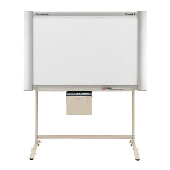
[Stand (option)]
Stand and wall-mounting kit are optional.
• Before operating this unit, please read these instructions completely.
After reading them, preserve them carefully for future reference.
• Because of the nature of the print film, all the printed text will remain on the film.
• This product is designed for installation by a qualified servicing dealer.
Installation performed by non-authorized individuals could cause safety-related problems with the operation of
this equipment.
• To locate the closest authorized dealer in your area, please call 1-800-449-8989.
Electronic Board
Operating Instructions
With Installation Manual
(for qualified service personnel)
UB-7325
Model No.
Advertisement
Chapters
Table of Contents

Related Manuals for Panasonic Panaboard UB-7325


Summary of Contents for Panasonic Panaboard UB-7325
-
Page 1: Operating Instructions
Installation performed by non-authorized individuals could cause safety-related problems with the operation of this equipment. • To locate the closest authorized dealer in your area, please call 1-800-449-8989. Electronic Board Operating Instructions With Installation Manual (for qualified service personnel) Model No. UB-7325... -
Page 2: Federal Communications Commission Requirements
Thank you for purchasing the Panasonic Electronic Board. For optimum performance and safety, please read these instructions carefully. • Thermal transfer film ....1 • Markers (red, black, and blue) ..1 each •... -
Page 3: Table Of Contents
• Removing Panasonic-DMS ........ -
Page 4: For Your Safety
For Your Safety For Your Safety CAUTION: TO PREVENT RISK OF ELECTRIC SHOCK HAZARD, DO NOT REMOVE THE COVER OF THIS PRODUCT, REFER SERVICING TO QUALIFIED SERVICE PERSONNEL. WARNING: TO PREVENT FIRE OR SHOCK HAZARD, DO NOT EXPOSE THIS PRODUCT TO RAIN OR ANY TYPE OF MOISTURE. -
Page 5: Precautions
Precautions Never remove the cover, take apart or modify the product. This will void the warranty. Do not put drinks, other liquids or heavy items on the tray or screen. Do not use the electronic board in an excessively humid or dusty location. Do not position the electronic board in a location where it is unstable. -
Page 6: Cd-Rom
Precautions Do not lean against the screen or on the cover (lower), even if the electronic board is mounted on the wall. CHOKING HAZARD Keep the marker’s cap out of reach of children to prevent swallowing. ■ CD-ROM To prevent the CD-ROMs from accidental damages: Do not touch or write on the surface of the disc. - Page 7 • Use a shielded USB cable that is certified as logo by USB-IF. • If you connect the electronic board to a USB hub, it is not guaranteed to work. • Do not connect two or more Panasonic electronic boards to a computer. It may cause the computer operation to become unstable.
-
Page 8: Part Names And Functions
Part Names and Functions Part Names and Functions Printer Output Port This port holds up to 10 sheets of output paper. Printer Open Lever Push down this lever to open the printer door. USB Connector (See page 17.) Scanner Screen One screen (with no ruled lines) of four screens can also be... -
Page 9: Control Panel
■ Control panel Contrast/Remaining Film Indicator Contrast Key Copy Key Panel Name Contrast/ Remaining Film Indicator Contrast Copy Key Multi-Copy/ Error Indicator Multi-Copy/ Stop Key Advance Reverse Reverse Key Advance Key Description This lamp indicator notifies the user when the time to replace the thermal transfer film is approaching (estimated) and of the printing contrast used during copying. -
Page 10: Installing The Thermal Transfer Film
Installing the Thermal Transfer Film Installing the Thermal Transfer Film Install the thermal transfer film in the printer. Set the power switch to on ( I ). • “ ” will flash on the Multi-Copy/Error Indicator when the thermal transfer film has run out. -
Page 11: Loading Copy Paper
Tighten the film, then close the printer door. 1) Rotate the blue gear in the direction of the arrow to take up the slack on the film. Blue gear • If a slack remains, perform step 3-2) through 4-1) again. 2) Securely close the printer door by using both hands until a click is heard. - Page 12 Loading Copy Paper Pull the paper cover forward as shown in the figure. To prevent paper jams such as those caused by multiple sheets feeding at once, fan the paper thoroughly, square it, align it with the guide inside, and insert as far as it will go. Guide Maximum paper limit Note...
-
Page 13: Making Copies
Making Copies This section describes how to copy text and illustrations drawn on the screen. Set the power switch to on ( I ). • “ ” will light on the Multi-Copy/Error Indicator to indicate that the unit is ready to copy. -
Page 14: Using The Projector Screen
Notes on Replacing Thermal Transfer Film • Only use the designated product (UG-6001) from Panasonic as the replacement film. (Note that using another type of replacement film may result in degraded printing quality or damage to the unit.) • Thermal transfer film is disposable. Dispose of used thermal transfer film as “burnable”... -
Page 15: Paper Jams
Paper Jams Remove paper jams by the following procedure when copy paper does not come out of the output port or when “ ” flashes on the Multi-Copy/Error Indicator. Push down the printer open lever to open the printer door. Remove the thermal transfer film with both hands. - Page 16 Paper Jams To prevent paper jams such as those caused by multiple sheets feeding at once, fan the paper thoroughly, square it, align it with the guide inside, and insert as far as it will go. Guide Maximum paper limit Note •...
-
Page 17: Computer Interfacing
Board Image Capture” on page 18. • If you connect the electronic board to a USB hub, it is not guaranteed to work. • Do not connect two or more Panasonic electronic boards to a computer. It may cause the computer operation to become unstable. -
Page 18: Installing Drivers / Board Image Capture
Computer Interfacing ■ Installing Drivers / Board Image Capture The USB, printer, TWAIN driver and Board Image Capture are installed in your computer by following procedures. Note • Do not yet connect a USB cable to the electronic board. Power on your computer and start Windows* •... -
Page 19: Installing Quick Image Navigator / Panasonic-Dms
For Windows 2000 / Windows XP / Windows Vista: Quick Image Navigator For Windows 98 / Windows Me: Panasonic-DMS If Panasonic-DMS is already installed, you do not need to uninstall it. Power on your computer and start Windows. • Log on as an administrator for Windows 2000, Windows XP or Windows Vista. -
Page 20: Removing Panasonic-Dms
Panasonic Quick Image Navigator. Follows the instructions on the screen. After uninstalling, restart your computer. ■ Removing Panasonic-DMS If you need to remove Panasonic-DMS, perform the following steps. Power on your computer and start Windows. Click [Start], move the pointer to Programs–... -
Page 21: Scanning With The Quick Image Navigator / Panasonic-Dms
For Quick Image Navigator: From the File menu, click Environment Setup..., click TWAIN tab, then click Select TWAIN- compliant scanning device... For Panasonic-DMS: Click the File menu, then click Select source... Select Panaboard UB5-7 USB TWAIN Driver and click [Select]. -
Page 22: Panaboard Operation Panel
Computer Interfacing ■ Panaboard Operation Panel It is possible to perform the same operations as with the electronic board control panel (page 9) from the following Panaboard Operation buttons. Note • While the Panaboard Operation Panel is displayed, the Copy Key on the electronic board control panel is used for scanning images into the computer. -
Page 23: Printing
Panel Name Copy Button Status Box About Button Help Button Close Button ■ Printing To print documents from the computer to the printer, select the Print menu of the application software and select the printer name set when installing. The standard printer name is “Panaboard-UB7 USB Printer (Letter)”. Note •... -
Page 24: Daily Care And Maintenance
Daily Care and Maintenance Daily Care and Maintenance Always turn off the power switch and unplug the power plug when cleaning outside and inside the unit. ■ Cleaning the screen and the unit Gently wipe the screen film and unit with a water- dampened cloth that has been thoroughly wrung. - Page 25 Clean the Printer Head Dampen the tip of a cotton swab in ethyl alcohol and gently wipe the printer head. Cotton swab Printer head (Gold) Note • Never touch the printer head or the surrounding area with your hands as this may disable copying.
-
Page 26: Help Troubleshooting
After the existing Panasonic-DMS software is uninstalled, the new Panasonic-DMS is installed. Install the new Panasonic-DMS again as follows. 1. Uninstall the current Panasonic-DMS. 2. Install the old Panasonic-DMS. 3. Install the new Panasonic-DMS in the same folder with the old one. Page – ”.) ”.) -
Page 27: Meanings Of Error Codes
If other indications such as “ ” appear, call your dealer. The old Panasonic-DMS is not uninstalled if the old version of the Panasonic-DMS has been installed before installing the new one. Uninstall the old Panasonic-DMS from the Add / Remove Programs of the Control Panel. -
Page 28: Specifications
UG-6001 (Set of 2 rolls [50 m (164 ft.)]) KX-B031 (set of 10 black markers), KX-B032 (set of 10 red markers), KX-B033 (set of 10 blue markers) KX-B042 (set of 6 erasers) one eraser) UB-7325 " × 10 " ) ° ° " × 4' 7 "... - Page 29 Installation Manual (for qualified service personnel) Table of Contents Assembling the Electronic Board ..... . . 30 ●Accessories for assembling ....... 30 ●Assembly .
-
Page 30: Assembling The Electronic Board
Assembling the Electronic Board ■ Accessories for assembling The package includes the parts for setting up the electronic board shown below. Make sure that all of these parts are included in the package before proceeding. Part Name Power cord Wall-mounting template Illustration Q’ty... -
Page 31: Assembly
■ Assembly Assemble the optional stand or wall-mounting kit. ■ If you are using a stand, refer to page 36. ■ If you are using a wall-mounting kit, refer to page 40. Remove the electronic board from the shipping box. Remove the joints, then remove the electronic board from the shipping box. - Page 32 Assembling the Electronic Board Install the electronic board. Install the electronic board using the stand (option) or wall-mounting kit (option). ■ Using the stand (option) 1) Hang the electronic board on the optional stand. • The electronic board can be mounted 200 mm (7 ”) higher than hang position A by hanging it with the wing bolts B.
-
Page 33: Connect The Power Cord
Connect the power cord. 1) Securely fit the supplied power cord into the AC inlet on the printer unit. 2) Fit the power cord into the cable holder. Wipe the screen film surface. Soak a soft cloth with water, wring well, and wipe the screen film surface. -
Page 34: Electronic Board Operations Check
Electronic Board Operations Check After assembling the electronic board, perform the procedures presented in the following table to make sure it functions properly. Step Turn on the power switch. Open the printer door and attach the accessory thermal transfer film, then close the printer door. -
Page 35: Repacking
Repacking Perform Assembly Steps 2 through 4 on pages 31 - 33 in reverse to repack the electronic board and accessories. Use the joints to fasten the shipping box. Power cord Markers Electronic board Joints Joints Caution • Do not touch the screen film surface, as this may damage it. Shipping box Thermal transfer film Eraser... -
Page 36: Assembling The Optional Stand (Kx-B061)
Assembling the Optional Stand (KX-B061) ■ Accessories The package box for the optional stand includes the parts noted below; please confirm that all parts are present before beginning installation Part name Stand base Pipe Cover Side bar (A) Side bar (B) Screw M8 x 45 mm (1 Fixture... -
Page 37: Assembly
■ Assembly Assembling the stand ■ Assembling the fall-prevention extension legs The fall-prevention extension legs increase the safety of the electronic board. Fall-prevention extension legs Caution • Install and always set the fall-prevention legs when using the stand. • When tightening the screw Note •... - Page 38 Assembling the Optional Stand (KX-B061) ■ Assembling the stand Note Do not tighten the screw Assemble with the holes toward the front. Pull the fall-prevention extension legs Locking down (fall-prevention extension legs casters side will be fixed by the lock pin.) (rear) Locking casters side (rear)
- Page 39 Attach the fixtures Assemble and install the electronic board. Refer to step 3 on page 32. Assembling the Optional Stand (KX-B061) with the four wing-bolts.
-
Page 40: Optional Wall-Mounting Kit (Kx-B063)
UB-7325 is 215 kgf (474 lbs.). 2. The position of the intended installation is of adequate size for the selected Panaboard. UB-7325 is 1,516 mm (H) × 1,648 mm (W) [5' (H) × 5' 5" (W)]. 3. An outlet is within 3 m (9' 10 ■... -
Page 41: Wall-Mounting Procedure
Caution The wall must be capable of supporting at least 2,108 N [215 kgf (474 lbs.)] for UB-7325. Tape the Wall-mounting template on the wall. • Do not use the template included in the wall-mounting kit (KX-B063), but rather the one included with the electronic board (UB-7325). -
Page 42: Attaching The Wall-Mounting Fixtures
Optional Wall-mounting Kit (KX-B063) ■ Attaching the wall-mounting fixtures The electronic board must be mounted with the method most suited to the material of the wall. Three methods are presented here. (Other options may be available in your area.) ● Attaching to metal or concrete walls Stud plugs (sold in stores) are needed. - Page 43 ● Attaching to plasterboard walls Split-wing toggles (sold in stores) are needed. Split-wing toggle Plasterboard Arms Arms ● Attaching to wooden walls Use wood screws (sold in stores). Wooden wall Optional Wall-mounting Kit (KX-B063) Insert each bolt through a hole Wall-mounting in the wall-mounting fixture and fixture...
- Page 44 Panasonic Communications Company of North America Unit of Panasonic Corporation of North America One Panasonic Way, Secaucus, New Jersey 07094 © 2004 Panasonic Communications Co., Ltd. All Rights Reserved. PJQXC0016XA-F F0904E4127...
Need help?
Do you have a question about the Panaboard UB-7325 and is the answer not in the manual?
Questions and answers