Advertisement
Advertisement
Table of Contents

Related Manuals for Fender Deluxe 112 plus


Summary of Contents for Fender Deluxe 112 plus
-
Page 1: Service Manual
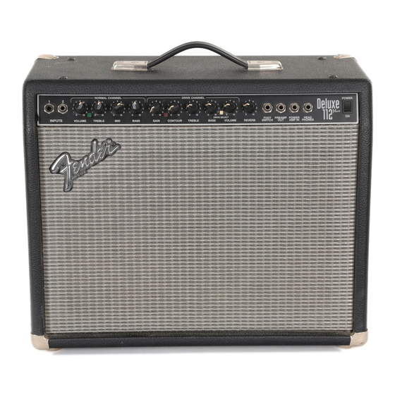
DELUXE 112 PLUS p/n 022-6702-000 (120V) SERVICE MANUAL CONTENTS: Notices Specifications Theory of operation Parts lists: PCB assembly Chassis assembly Footswitch assembly Cabinet assembly Miscellaneous Schematics/diagrams Fender Musical Instruments Corp. 7975 North Hayden Road Scottsdale, AZ 85258... -
Page 2: Important Notice
Fender Musical Instruments Co. All specifications subject to change without notice. For warranty repair service, only Fender specified part numbers are to be used. It is recommended they also be used for post-warranty maintenance and repair. -
Page 3: Specifications
DELUXE 112 PLUS SPECIFICATIONS Product Release No.: PR 291 (This is not a model number) Part Number: 120V Version : 22-6702 100V 22-6772 230V 22-6762 Power Requirements: 180-120VAC, 50-60 Hz, 360W max. 230-240VAC, 50 Hz, 360w max. Input impedance: Input 1: 850kΩ... -
Page 4: Channel Switching
DELUXE 112 PLUS THEORY OF OPERATION Input 1 is a high sensitivity input. Input 2 is a low sensitivity input. Inputs 1 and 2 contain series switches that connect to +16Vdc via a third series switch located within the Power Amp in jack (J5). From the input jacks, this series circuit terminates at the gate of JFET Q7. -
Page 5: Parts List
PARTS LIST PRINTED CIRCUIT BOARD ASSEMBLY PART # DESCRIPTION REFERENCE DESIGNATION 048873001 PCB ASSY DELUXE 112 PLUS (STUFFED) 031910 BREAKER THERMAL 15A 155/195DEG 048451 BUTTON PUSH OFF WHITE 028577 CABLE REVERB 30”... - Page 6 JUMPER WIRE 22GA W1-60 028098 LED 5X5MM GREEN SLB-55MG3 028039 LED RED 5X5MM SLB-55VR3 9902202281 LED RED LUMEX CS02 LD1,2 048872 PCB FAB DELUXE 112 PLUS (RAW BOARD) 024947 R4,5,45 RES CF 1/4W 5% 47Ω 024957 R101,106 RES CF 1/4W 5% 270Ω...
-
Page 7: Chassis Assembly
028115 XSTR PNP TIP 147 TO-218AC Q2,11 CHASSIS ASSEMBLY PART # DESCRIPTION REFERENCE DESIGNATION 048879 CHS ASSY DELUXE 112 PLUS (COMPLETE CHASSIS 120V) 021709 BUSHING SR .437X.062X 13/32 BLK (@ SPEAKER CABLE) 026116 BUSHING SR .500X.063X7/16 BLK (@ REVERB CABLE) 026038 BUSHING SR .625X.062X37/64 BLK... -
Page 8: Reference Designation
DELUXE 112 PLUS CABINET ASSEMBLY (CONT) PART # DESCRIPTION REFERENCE DESIGNATION 029527 WSHR FNSH 8-5/8 FLNGD BLX WX (CHASSIS MOUNT) MISCELLANEOUS PART # DESCRIPTION REFERENCE DESIGNATION 048877 MANUAL OWNERS DLX 112 PLUS 048871 SCHEM REDU DLX 112 PLUS W/ SERV...
Need help?
Do you have a question about the Deluxe 112 plus and is the answer not in the manual?
Questions and answers