Table of Contents
Advertisement
SERVICE MANUAL
Fender® Musical Instruments Corp. 8860 East Chaparral Road Suite 100 Scottsdale, AZ 85250
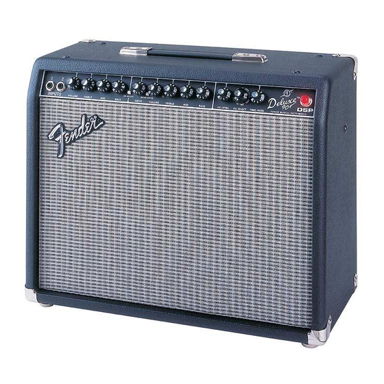
DELUXE™ 90 DSP
(This is the model name for warranty claims)
p/n 2267200030 (120V)
CONTENTS:
.............................. 2
Specifications.................... 3
Notes.................... 4
Description............. 5
Assembly............ 6
......... 9
.... 10
.. 11
12
........... 13
Advertisement
Table of Contents

Related Manuals for Fender DELUXE 90 DSP


Summary of Contents for Fender DELUXE 90 DSP
-
Page 1: Table Of Contents
Notes....4 Circuit Description..... 5 Parts Lists: Assembly.... 6 uDSP Assembly ..9 Chassis Assembly ..10 End Item Assembly .. 11 Footswitch Assembly Service Diagrams ... 13 Fender® Musical Instruments Corp. 8860 East Chaparral Road Suite 100 Scottsdale, AZ 85250... -
Page 2: Notices
CONFIDENTIAL electronically or otherwise must be surrendered and PROPRIETARY and is the property of upon demand of Fender Musical Instruments Cor- Fender® Musical Instruments Corporation. It is poration. not to be sold or assigned to another party and is disclosed solely for use by Fender Authorized •... -
Page 3: Specifications
DELUXE™ 90 DSP (This is the model name for warranty claims) SPECIFICATIONS Model Name: Deluxe 90 DSP Release Number: PR 516 (Not a model number) Part Numbers (120V, 60Hz) US: 2268200030 (110V, 60Hz) TW: 2268201030 (240V, 50Hz) AUS: 2268203030 (230V, 50Hz) UK:... -
Page 4: Service Notes
(This is the model name for warranty claims) SERVICE NOTES 1. CHASSIS REMOVAL is accomplished by de- 3. Deluxe 90 DSP MAIN PCB REMOVAL is ac- taching the speaker wires from the speaker, complished by first disconnecting the Speaker removing four (4) screws from the top of the wires from P1 &... -
Page 5: Circuit Description
Q16 and Q17 This overview is focused for the efficient use and provide voltage multiplication for output bias. Q20 security of Fender® proprietary information. and Q21 are Darlington drivers for output devices Q22 and Q23. Q18 and Q19 provide over-current protection. -
Page 6: Parts Lists: Pcb Assembly
Unique Fender® part. Order directly from the Fender® dealer Customer Service Department. ** Safety Requirement part. Replacement must match Safety Agency…–Value, if specified –Type, if specified –Approval Mark(s) if on part. ** Both a unique Fender® part and a Safety Requirement part as defined above. - Page 7 Unique Fender® part. Order directly from the Fender® dealer Customer Service Department. ** Safety Requirement part. Replacement must match Safety Agency…–Value, if specified –Type, if specified –Approval Mark(s) if on part. ** Both a unique Fender® part and a Safety Requirement part as defined above.
- Page 8 Unique Fender® part. Order directly from the Fender® dealer Customer Service Department. ** Safety Requirement part. Replacement must match Safety Agency…–Value, if specified –Type, if specified –Approval Mark(s) if on part. ** Both a unique Fender® part and a Safety Requirement part as defined above.
-
Page 9: Udsp Assembly
Unique Fender® part. Order directly from the Fender® dealer Customer Service Department. ** Safety Requirement part. Replacement must match Safety Agency…–Value, if specified –Type, if specified –Approval Mark(s) if on part. ** Both a unique Fender® part and a Safety Requirement part as defined above. -
Page 10: Chassis Assembly
Unique Fender® part. Order directly from the Fender® dealer Customer Service Department. ** Safety Requirement part. Replacement must match Safety Agency…–Value, if specified –Type, if specified –Approval Mark(s) if on part. ** Both a unique Fender® part and a Safety Requirement part as defined above. -
Page 11: End Item Assembly
Unique Fender® part. Order directly from the Fender® dealer Customer Service Department. ** Safety Requirement part. Replacement must match Safety Agency…–Value, if specified –Type, if specified –Approval Mark(s) if on part. ** Both a unique Fender® part and a Safety Requirement part as defined above. -
Page 12: Footswitch Assembly
Unique Fender® part. Order directly from the Fender® dealer Customer Service Department. ** Safety Requirement part. Replacement must match Safety Agency…–Value, if specified –Type, if specified –Approval Mark(s) if on part. ** Both a unique Fender® part and a Safety Requirement part as defined above. -
Page 13: Service Diagrams
(This is the model name for warranty claims) Schematics and Drawings Service Diagram (Schematic) ....Deluxe 90 DSP Service Diagram (PCB Assy) ....Deluxe 90 DSP Service Diagram (Schematic) ....Micro DSP Service Diagram (PCB Assy) ....Micro DSP Chassis Assy ....Deluxe 90 DSP End Item Assy ....Deluxe 90 DSP...
Need help?
Do you have a question about the DELUXE 90 DSP and is the answer not in the manual?
Questions and answers