Table of Contents
Advertisement
Quick Links
Advertisement
Table of Contents

Related Manuals for Panasonic HDX900


Summary of Contents for Panasonic HDX900
-
Page 1: Operating Instructions
Operating Instructions Camera-Recorder Model No. Before operating this product, please read the instructions carefully and save this manual for future use. ENGLISH F0706W1106 -F @ Downloaded From CamcorderManual.com Panasonic Manuals VQT0X86-1 Printed in Japan... - Page 2 The CCD may be damaged if it is subjected to light from a laser beam. When using the camera-recorder in locations where laser irradiation equipment is used, be careful not to allow the laser beam to shine directly on the lens. Downloaded From CamcorderManual.com Panasonic Manuals...
- Page 3 The CCD may be damaged if it is subjected to light from a laser beam. When using the camera-recorder in locations where laser irradiation equipment is used, be careful not to allow the laser beam to shine directly on the lens. Downloaded From CamcorderManual.com Panasonic Manuals...
- Page 4 O For the removal of the battery for disposal at the end of its service life, please consult your dealer. O Raadpleeg uw leverancier over de verwijdering van de batterij op het moment dat u het apparaat bij einde levensduur afdankt. Downloaded From CamcorderManual.com Panasonic Manuals...
-
Page 5: Table Of Contents
5-3 Adjusting the white shading of the lens ... 84 4-4-1 Selecting the audio input signals ..... 37 4-4-2 Adjusting the audio signal recording levels ..37 4-4-3 CH3 and CH4 recording levels ......38 Downloaded From CamcorderManual.com Panasonic Manuals... - Page 6 OUniSlot is a trademark of Ikegami Tsusinki co., Ltd. 7-3-12 CAMERA SETTING ........114 O“DOLBY” and the double-D symbol Î are trademarks of Dolby Laboratories Licensing Corporation. OOther names of companies and products are trademarks or registered trademarks of the respective companies. Downloaded From CamcorderManual.com Panasonic Manuals...
-
Page 7: Chapter 1 General
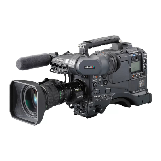
Chapter 1 General The AJ-HDX900 is a video camera-recorder that integrates an HD camera part equipped with a progressive scan (full pixel reading) 3-CCD camera unit featuring a 2/3-inch on-chip lens with a VTR that in turn supports the DVCPRO HD-LP format. -
Page 8: Features Of The Vtr Unit
REC start/stop. Since a tally lamp can be used by connecting the LED to this connector, it is useful for shooting video when fixing the camera on a crane. (Refer to page 89) Downloaded From CamcorderManual.com Panasonic Manuals... -
Page 9: Other Featuresa
On the side panel of the unit, three user buttons are available. For the respective buttons, it is possible to allocate functions that are used frequently. (Refer to page 62) 1-5 Dimensions drawing Unit: mm (inch) 129 (5- 329 (13) 62 (2- Downloaded From CamcorderManual.com Panasonic Manuals... -
Page 10: System Configuration
AJ-HT901G SHAN-TM700 <Note> All of the devices and accessories other than the unit, which are shown in this system configuration, are optionally available. To use these devices and accessories, refer to the respective operation manuals. Downloaded From CamcorderManual.com Panasonic Manuals... -
Page 11: Chapter 2 Parts And Their Functions
Use this to attach the video light, etc. 8 Lens mount (bayonet type) The lens is attached to this mount. 9 Lens lever This lever is tightened to secure the lens after it has been attached to the lens mount. Downloaded From CamcorderManual.com Panasonic Manuals... -
Page 12: Audio Function Section
CH1/CH2 connectors 5 are recorded. <Note> When you use stereo microphone (AJ-MC900G optional), set both CH1 and CH2 to [FRONT]. The signal from L CH is recorded to CH1 and that from R CH to CH2. Downloaded From CamcorderManual.com Panasonic Manuals... - Page 13 This is used to adjust the volume of the warning alarms from the earphones which have been connected to the speaker > or PHONES jack ?. The warning alarms are not audible when this control is at its lowest setting. Downloaded From CamcorderManual.com Panasonic Manuals...
-
Page 14: Shooting And Recording/Playback Function Section
AWB side or to the ABB side, the automatic adjustment for the side pressed will be stopped. The adjusted value in this case is the value before automatic adjustment was performed. Downloaded From CamcorderManual.com Panasonic Manuals... - Page 15 O When the prescribed amount of time has elapsed in the STBY mode, the unit is automatically set to the SAVE mode. To return the unit to the STBY mode, set the VTR SAVE/STBY switch to SAVE, and then again to the STBY position. Downloaded From CamcorderManual.com Panasonic Manuals...
- Page 16 Also, it is not possible to externally lock the sub carrier of the unit’s down-converter output (composite video signal). O Returned video images can be confirmed in the viewfinder screen by entering HD-Y signals. Downloaded From CamcorderManual.com Panasonic Manuals...
-
Page 17: Menu Operation Section
When this lamp is lighted, refrain from inserting or displayed on the display panel of the FS-100. removing the card. If it is used in 720P mode, frame rates are not displayed properly but video images will be recorded properly. Downloaded From CamcorderManual.com Panasonic Manuals... -
Page 18: Time Code Related Section
This is used to display the time code, CTL or user bits on the counter display section depending on the setting positions of this switch and the TCG switch 9. : The user bits are displayed. : The time code is displayed. CTL : CTL is displayed. Downloaded From CamcorderManual.com Panasonic Manuals... -
Page 19: Warning/Status Display Section
Warning displays Clogged video head SERVO: Servo disturbance HUMID: Formation of condensation on the head drum SLACK: Problem in tape take-up For details, refer to “6-3 Warning system.” Downloaded From CamcorderManual.com Panasonic Manuals... - Page 20 When UB has been selected by the DISPLAY switch, each time the HOLD button is pressed, the setting is switched in the following sequence: VTCG (VTC) 5 DATE 5 TIME 5 no display (time zone) 5 TCG (TC) and so on repeatedly. Downloaded From CamcorderManual.com Panasonic Manuals...
-
Page 21: Viewfinder Section
It also flashes to provide a warning display like the REC lamp inside the viewfinder. The lamp’s brightness (HIGH or LOW) when it is lighted can be selected using the TALLY switch. Downloaded From CamcorderManual.com Panasonic Manuals... -
Page 22: Chapter 3 Recording And Playback
SAVE Cassette holder Insert the cassette tape and press the part marked with the arrow to close the cassette holder securely. <Note> Check that there is no slack in the tape of the cassette. Downloaded From CamcorderManual.com Panasonic Manuals... -
Page 23: Basic Procedures
EJECT button to open the cassette holder. After checking the following points, insert the cassette tape and close the cassette holder. ≥ Position of the accidental erasure prevent tab ≥ Tape slack MODE CHECK button Downloaded From CamcorderManual.com Panasonic Manuals... - Page 24 To stop the recording, press the REC START button again. The REC lamp inside the viewfinder goes off. Tape function buttons During recording, the tape function buttons (EJECT, REW, FF, PLAY/PAUSE and STOP) will not work. Downloaded From CamcorderManual.com Panasonic Manuals...
-
Page 25: Scene-To-Scene Continuity
PRESET, the time code will always be regenerated to the value on the tape by executing the jump operation after setting the TCG switch to the R-RUN position. 2 seconds 2 seconds 5 seconds Recorded Unrecorded section section Forward direction of the tape Downloaded From CamcorderManual.com Panasonic Manuals... -
Page 26: To Record Video Signals Of A Few Seconds Before Starting Recording (Pre-Recording Function)
A value from 0 to 7 seconds is set as the length of time for which the video and audio signals can be recorded before the REC START button or the VTR button on the lens is pressed. Downloaded From CamcorderManual.com Panasonic Manuals... -
Page 27: Recording In Intervals (Interval Rec Function)
2 minutes or more, the tally lamp blinks at 5 second intervals to indicate when recording is paused. Under these conditions, the tally lamp will also flash 3 seconds before recording starts. Downloaded From CamcorderManual.com Panasonic Manuals... - Page 28 POWER switch on the unit is turned off. 2) Perform a menu operation and select OFF as the INTERVAL REC MODE item setting. Downloaded From CamcorderManual.com Panasonic Manuals...
-
Page 29: To Take The Previous Cut Again (Retake Function)
<USER SW> screen from the OPERATION page and + REW), high-speed fast forward playback mode (FF) or selecting settings for the USER MAIN SW, USER1 SW and high-speed rewind playback mode (REW). USER2 SW items by performing menu operations. Downloaded From CamcorderManual.com Panasonic Manuals... -
Page 30: Chapter 4 Adjustments And Settings For Recording
The settings for SYSTEM MODE item will change when the POWER switch of the unit is turned “OFF” and then turned “ON” again. O Retain the state where the POWER switch of the unit is turned OFF for at least 5 seconds. Downloaded From CamcorderManual.com Panasonic Manuals... -
Page 31: Recording Format On Tapes And Signal Format At Output Connector
24P Over 60i (2-3-3-2 Pull-down) the same video signals as video signals for 2 frames and records 1080-50i them on tape. 25P Over 50i 720-59.94P 30P Over 60P 24P Over 60P (2-3 Pull-down) 720-50P 25P Over 50P Downloaded From CamcorderManual.com Panasonic Manuals... -
Page 32: Adjusting The White Balance And Black Balance
<Notes> ≥ Take care to keep high-brightness spots off the screen. ≥ Shoot white objects in the center of the screen. At least one-fourth of the screen width At least one-fourth of the screen height Downloaded From CamcorderManual.com Panasonic Manuals... - Page 33 This unit contains four filters so that a total of 8 (4a2) adjustment values are saved. When the S. GAIN function operates, the AWB switch is not activated and is the PRST value of the WHITE BAL switch. Downloaded From CamcorderManual.com Panasonic Manuals...
-
Page 34: Adjusting The Black Balance
CLOSE. Adjustment is completed in several seconds. message similar to the one shown in the figure below now appears.) The adjustment value is automatically saved in the memory. A B B O K Downloaded From CamcorderManual.com Panasonic Manuals... -
Page 35: Setting The Electronic Shutter
1/24.1 to 1/249.8 1080-23.98PA 24PA 1/24.1 to 1/249.8 720-59.94P 1/60.3 to 1/249.8 720-29.97P 1/30.2 to 1/249.8 720-23.98P 1/24.1 to 1/249.8 1080-50i 1/50.2 to 1/209.5 1080-25P 1/25.2 to 1/209.5 720-50P 1/50.2 to 1/209.5 720-25P 1/25.2 to 1/209.5 Downloaded From CamcorderManual.com Panasonic Manuals... -
Page 36: Setting The Shutter Mode And Speed
Press the SHUTTER switch from ON to SEL. SHUTTER switch SYNCHRO SCAN (+ and –) buttons In the SYNCHRO SCAN mode, it is possible to change the shutter speed continuously by operating the SYNCHRO SCAN (+ and –) buttons. SHUTTER switch Downloaded From CamcorderManual.com Panasonic Manuals... -
Page 37: Selecting The Audio Input Signals And Adjusting Their Recording Levels
FRONT MIC POWER REAR MIC POWER MONITOR SELECT :STEREO FRONT MIC LEVEL :–40dB REAR MIC CH1 LVL :–60dB REAR MIC CH2 LVL :–60dB REAR LINE IN LVL :0dB AUDIO OUT LVL :0dB HEADROOM :18dB WIRELESS WARN :OFF Downloaded From CamcorderManual.com Panasonic Manuals... -
Page 38: Ch3 And Ch4 Recording Levels
UP (+) button: This increments the numerical value of the flashing digit by 1. DOWN (–) button: This decrements the numerical value of the flashing digit by 1. Set the TCG switch to F-RUN or R-RUN. Downloaded From CamcorderManual.com Panasonic Manuals... - Page 39 VITC UB MODE item) User bits information recorded LTC UB automatically. (Camera video Upper 6 digits can be recorded. image signals) VITC UB (In accordance with the settings in the VITC UB MODE item) Downloaded From CamcorderManual.com Panasonic Manuals...
- Page 40 • • • Frame rate: 30P Over 60i (2:2) 25P Over 50i (2:2) Time code frame digit • • • Image Ao Ae Bo Be Co Ce • • • Updated frame information • • • Downloaded From CamcorderManual.com Panasonic Manuals...
- Page 41 • • • 4: 50.00 Hz Active frame information 5: 59.94 Hz • • • Tape management information OActive frame information OREC START/STOP mark 0 2 : 4 0 : 2 4 : 5 0 Downloaded From CamcorderManual.com Panasonic Manuals...
-
Page 42: Setting The Internal Clock's Date And Time
Check the time zone time. setting again. (There is no need to set the date and time again.) Set the TCG switch to F-RUN or R-RUN to fix the time zone. Downloaded From CamcorderManual.com Panasonic Manuals... -
Page 43: Setting The Time Code
(approx. 1 year). <Note> If the POWER switch is turned on, then off, and then on again, the free-run time code backup accuracy is approximately ±2 frames. Downloaded From CamcorderManual.com Panasonic Manuals... - Page 44 For locking the down converter output VIDEO IN SDI IN signals to the GENLOCK input. HD SDI IN For the HD SDI output signals, the start position of the video gains by about 90 lines. REF IN Downloaded From CamcorderManual.com Panasonic Manuals...
- Page 45 TC OUT AJ-HDX900 2nd unit and later Settings of the TC TC IN VIDEO SYNCRO item: 0 GENLOCK IN TC OUT AJ-HDX900 TC IN Settings of the TC VIDEO SYNCRO item: 0 GENLOCK IN TC OUT Downloaded From CamcorderManual.com Panasonic Manuals...
- Page 46 To release the external lock First stop supplying the external time code, and set the TCG switch to R-RUN. Downloaded From CamcorderManual.com Panasonic Manuals...
-
Page 47: Setting The Umid Information
Press the JOG dial button to enter the character. Turn the JOG dial button to set the following characters. When the JOG dial button is pressed, the arrow (cursor) returns to the “USER” item. Press the MENU button to exit the menu operations. Downloaded From CamcorderManual.com Panasonic Manuals... -
Page 48: Menu Displays On The Viewfinder Screen
VTR MENU: This item is used to perform the maintenance and inspections related to this unit’s VTR unit. USER MENU SELECT: This item is used for editing the USER MENU. Downloaded From CamcorderManual.com Panasonic Manuals... -
Page 49: Selecting The User Menus
42 in the case of camera related items (3 pages’ worth, with 14 items per page, 14 a 3 = 42) or 14 in the case of VTR related items (1 page’s worth, or 14 items). Downloaded From CamcorderManual.com Panasonic Manuals... -
Page 50: Viewfinder Screen Status Displays
(temporary stop time) has elapsed. After two minutes in the play-pause mode, the SAVE mode is established automatically, and the lamp lights. Downloaded From CamcorderManual.com Panasonic Manuals... - Page 51 ON appears if the front CH1 control is enabled and OFF appears if it enable/disable) is disabled. CH2: ON/OFF ON appears if the front CH2 control is enabled and OFF appears if it is disabled. Downloaded From CamcorderManual.com Panasonic Manuals...
- Page 52 (Y GET value) With the Y GET ON setting, the output brightness level near the ¢¢¢.¢% center marker is displayed as “%.” (MARKER display) MKR: A/B/OFF This indicates the type of marker presently being displayed. Downloaded From CamcorderManual.com Panasonic Manuals...
- Page 53 This indicates the TCR (time code reader) value. (V)UBG AB CD EF 00 This indicates the UBG VUBG display. (V)UBR 12 34 56 78 This indicates the UBR VUBR display. –01:59:59:20 This indicates the CTL-COUNTER value. Downloaded From CamcorderManual.com Panasonic Manuals...
- Page 54 COMP This appears when setting the mode for suppressing distortion of M Compression compressed video images that may occur when dark parts are shot. mode Downloaded From CamcorderManual.com Panasonic Manuals...
- Page 55 — ≤ ≤ ≤ ≤ ≤: The display does not appear when OFF has been selected for the STATUS item setting on the <MODE CHK IND> screen. µ: Display always appears regardless of the menu. Downloaded From CamcorderManual.com Panasonic Manuals...
-
Page 56: Display Modes And Setting Changes/Adjustment Result Messages
To check the settings for TABLE B, press Turn the JOG dial button to move the arrow (cursor) to the MARKER SELECT so that MKR:B is displayed. the “ID 1: to 3:” item. Downloaded From CamcorderManual.com Panasonic Manuals... -
Page 57: Mode Check Screen Displays (Mode Check Button Function)
A marker information and “4:3” is selected for the FRAME SIG item as the B marker information, then the 16:9 and 4:3 aspect ratios can be checked easily by operating the MARKER SELECT button as and when required. Downloaded From CamcorderManual.com Panasonic Manuals... -
Page 58: Selection Of Video Output Signals
Set the characters to be superimposed on the signals output from the VIDEO OUT connector by using the VIDEO OUT CHARACTER switch and the OUTPUT ITEM item on the menu (<OUTPUT SEL> screen on the SYSTEM SETTING page). VIDEO OUT CHARACTER switch Downloaded From CamcorderManual.com Panasonic Manuals... - Page 59 For setting the horizontal position of the user box center. USER BOX V POS –50 For setting the vertical position of the user box center. O The user box can be displayed in any position as a box- type cursor. Downloaded From CamcorderManual.com Panasonic Manuals...
-
Page 60: Settings Of Signals Output From Mon Out Connector
For setting the horizontal position of the user box center. USER BOX V POS –50 For setting the vertical position of the user box center. O The user box can be displayed in any position as a box- type cursor. Downloaded From CamcorderManual.com Panasonic Manuals... -
Page 61: Menu-Driven Function Setup
S.GAIN:An analog gain increase with an asterisk is one that is valid. One without an asterisk is invalid. DS.GAIN: A cumulative gain increase with an asterisk is one that is valid. One without an asterisk is invalid. Downloaded From CamcorderManual.com Panasonic Manuals... -
Page 62: Allocating Functions To The User Main, User1 And User2 Buttons
– –: The aperture is stopped down by a full stop. No display: The reference value remains unchanged. S.BLK: The SUPER BLACK function is allocated. This function reduces the black level to below the pedestal level. Downloaded From CamcorderManual.com Panasonic Manuals... -
Page 63: Setting The Color Temperature Manually
A or B position of the WHITE BAL switch. #< WHITE BALANCE MODE > FILTER INH SHOCKLESS AWB :NORMAL AWB AREA :25% COLOR TEMP PRE :3200K AWB A TEMP :4300K AWB B TEMP :5600K Downloaded From CamcorderManual.com Panasonic Manuals... -
Page 64: Set Data Handling
WRITE SD memory card : Files built in the unit Lens file No. of files: 8k8 : Menu operations It is possible to write eight titles for eight lens files on the SD memory card. Downloaded From CamcorderManual.com Panasonic Manuals... -
Page 65: Handling The Setup Card
Bear in mind the following points when using and saving the setup cards. ≥ Avoid high temperatures and high humidity levels. ≥ Keep the cards away from water. ≥ Avoid exposing the cards to electrical charges. CONFIG OK Downloaded From CamcorderManual.com Panasonic Manuals... - Page 66 Turn the JOG dial button to select a number from 1 to 8, and press the JOG dial button. Turn the JOG dial button to move the arrow (cursor) to the next position (right), and repeat steps 6 and 7 to set the characters (maximum of 8). Downloaded From CamcorderManual.com Panasonic Manuals...
- Page 67 Turn the JOG dial button to select any number from 1 to WRITE NG ERROR The card may be defective. 8, and press the JOG dial button. (the data cannot be saved) Replace it. WRITE NG Remove the card to cancel write WRITE PROTECT protect. Downloaded From CamcorderManual.com Panasonic Manuals...
- Page 68 READ? Turn the JOG dial button to move the arrow (cursor) to YES, and press the JOG dial button. When the data loading is completed, the following message appears. READ OK Downloaded From CamcorderManual.com Panasonic Manuals...
-
Page 69: How To Use The User Data
Turn the JOG dial button to move the arrow (cursor) to YES, and press the JOG dial button. The setting data is now written in the user data area of the unit’s internal memory. Press the MENU button to exit the menu operations. Downloaded From CamcorderManual.com Panasonic Manuals... -
Page 70: How To Use The Scene File Data
Turn the JOG dial button to move the arrow (cursor) to the WRITE item. < SCENE > READ USER DATA SCENE SEL READ WRITE RESET TITLE1 : ******** TITLE2 : ******** TITLE3 : ******** TITLE4 : ******** Downloaded From CamcorderManual.com Panasonic Manuals... - Page 71 Press the MENU button to exit the menu operations. Press the MENU button to exit the menu operations. Downloaded From CamcorderManual.com Panasonic Manuals...
- Page 72 (right), and repeat steps 4 and 5 to set the characters (maximum of 8). When the title has been input, turn the JOG dial button to move the arrow (cursor) to the “:” position. Downloaded From CamcorderManual.com Panasonic Manuals...
-
Page 73: Method For Returning To User Settings
Move the arrow (cursor) to YES by turning the JOG dial button, and then press the JOG dial button. The unit is reset to the factory settings. O User data is not changed. Press the MENU button to exit the menu operations. Downloaded From CamcorderManual.com Panasonic Manuals... -
Page 74: Lens File
LENS R OFFSET item. Example of the chart for flare adjustment In the same way, adjust the signal level of Bch to be the same as Gch in the LENS B OFFSET item. 0.1H 0.1L Downloaded From CamcorderManual.com Panasonic Manuals... -
Page 75: To Save The Lens File Into The Built-In Memory
R E S E T A L L W R I T E R E S E T A L L n T I T L E : T I T L E : 222222222222 Downloaded From CamcorderManual.com Panasonic Manuals... - Page 76 WRITE or if the menu is exited. Press the MENU button twice upon completion of the adjustment. The setting menu is cleared, and the displays showing the unit’s current statuses appear at the top and bottom of the viewfinder screen. Downloaded From CamcorderManual.com Panasonic Manuals...
-
Page 77: To Read The Lens File From The Built-In Memory
C A R D C O N F I G R E A D U S E R D A T A T I T L E R E A D ? Y E S Downloaded From CamcorderManual.com Panasonic Manuals... -
Page 78: To Write In And Read Out The Lens File To/From The Sd Memory Card
Now perform step on page 75 through step on page A total of 64 lens files (8 lens files k 8 titles) can be saved on an SD memory card. Downloaded From CamcorderManual.com Panasonic Manuals... - Page 79 For this reason, save the lens files in the internal memory onto the SD memory card first to back them up before loading them on the SD memory card. Downloaded From CamcorderManual.com Panasonic Manuals...
-
Page 80: Chapter 5 Preparation
<BATTERY/TAPE> screen on the VTR FUNCTION page. For details, refer to “7-8-3 BATTERY SETTING1.” Anton/Bauer batteries which can be used O PROPAC14 O TRIMPAC14 O HYTRON50 O HYTRON100 O HYTRON120 O DIONIC90 O DIONIC100 O DIONIC160 Downloaded From CamcorderManual.com Panasonic Manuals... - Page 81 Address all inquiries concerning the V-mount adapter plate to your dealer. Using the V-mount type battery pack Attach the V-mount adapter plate. Insert it in the direction shown by the arrows, and slide it into place. Downloaded From CamcorderManual.com Panasonic Manuals...
-
Page 82: Use Of The External Dc Power Supply
POWER switch on the unit is turned on. In the case of the reverse operation, a malfunction may occur on the unit since the output voltage of the external DC power supply is raised slowly. Downloaded From CamcorderManual.com Panasonic Manuals... -
Page 83: Attaching The Lens And Adjusting The Flange Back
Proceed with the flange back adjustment for the lens. <Notes> ≥ For details on how to handle the lens, refer to the operating instructions of the lens. ≥ While the lens is removed, attach the mount cap to protect the unit. Downloaded From CamcorderManual.com Panasonic Manuals... -
Page 84: Adjusting The White Shading Of The Lens
Shoot a white sheet of paper with no unevenness of color. <Note> Since fluorescent lights, mercury lamps and other such kinds of lighting tend to flicker, use a light source which is free from flicker such as sunlight or a halogen lamp. Downloaded From CamcorderManual.com Panasonic Manuals... - Page 85 This now completes the white shading adjustments. The adjustment values are now stored in the non-volatile memory so that even when the unit’s power is turned off, there will be no further need to perform the white shading adjustment. Downloaded From CamcorderManual.com Panasonic Manuals...
-
Page 86: Audio Input Signal Preparations
Connect the microphone’s connecting cable to the MIC IN jack on the camera. MIC IN jack Set the AUDIO IN switch or switches to “FRONT” in accordance with the audio channel or channels whose sound is to be recorded. AUDIO IN switches Downloaded From CamcorderManual.com Panasonic Manuals... -
Page 87: When Using An Audio Component
Bear in mind that the unit cannot be attached if the pin remains in the center. Downloaded From CamcorderManual.com Panasonic Manuals... -
Page 88: Attaching The Shoulder Belt
LEVEL control, and secure the accessory knob to the control and unit behind using the same screw (accessory). Make sure that the index mark on the knob side is aligned with the index mark on the control side. Downloaded From CamcorderManual.com Panasonic Manuals... -
Page 89: Connection Of The Remote Control Unit (Aj-Rc10G)
TALLY ON: Low impedance TALLY OFF: High impedance 3: REC start/stop switch REMOTE connector This is connected in parallel to the REC START button on the unit or the VTR button on the lens 4: +12V Downloaded From CamcorderManual.com Panasonic Manuals... -
Page 90: Chapter 6 Maintenance And Inspections
≥ The cassette tape must not be set to the accidental erasure prevention mode. ≥ There must be no tape slack. ≥ The tape must be free from condensation. 3, 4 Downloaded From CamcorderManual.com Panasonic Manuals... -
Page 91: Inspecting The Vtr Unit
Press the REW button, and after the tape has been rewound for a few seconds, press the PLAY/PAUSE button. Check that the tape is recorded, played back and rewound properly. Press the FF button, and check that the tape is fast forwarded properly. Downloaded From CamcorderManual.com Panasonic Manuals... -
Page 92: Self-Diagnosis Function
Set the DISPLAY switch to UB. Check that pressing the HOLD button advances the display value through the sequence VTCG > DATE > TIME > no display (time zone) > TCG. Downloaded From CamcorderManual.com Panasonic Manuals... -
Page 93: Maintenance
For shooting in a high temperature environment using the DS GAIN, red, green, or blue dots may appear on the screen. Adjust the DS. GAIN and the S. GAIN in accordance with the operating environment. Downloaded From CamcorderManual.com Panasonic Manuals... -
Page 94: Connectors And Signals
L CH OUT (C) L CH IN(C) R CH OUT (H) R CH IN(H) R CH OUT (C) R CH IN(C) Matsushita part number K1AB105B0002 Maker part number HA16RD-5P (76) Maker part number NC5FBH (Hirose Denki) (NEUTRIK) PUSH Downloaded From CamcorderManual.com Panasonic Manuals... - Page 95 FRONT AUDIO LEVEL adjustment (not used) VR-GND GND for the FRONT AUDIO LEVEL (not used) UNREG-GND Caution: Total amount of current from the respective connectors for DC OUT, REMOTE, VF, and LENS should not exceed 2.5 A. Downloaded From CamcorderManual.com Panasonic Manuals...
- Page 96 Transmission data from the camera to the GPS unit GPS VBAT Backup power supply connector for the GPS unit (DC+3.3 V) REC START SW Control signals of REC start/stop GPS VCC Power supply connector for the GPS unit (DC+3.3 V) GPS GND Downloaded From CamcorderManual.com Panasonic Manuals...
- Page 97 Not used VIDEO RET Not used VIDEO EN Not used RM 1 (RM CLK) Not used RM 2 (RM DATA) Not used RM 3 (RM WR) Not used RM +5V Not used RM GND Not used Downloaded From CamcorderManual.com Panasonic Manuals...
-
Page 98: Warning System
“HUMID” display fails to be cleared even when the power is turned back on, wait until it clears. VTR unit operation Operation is stopped during recording, playback and fast forwarding. Corrective action Rewind the tape or replace the cassette tape. Downloaded From CamcorderManual.com Panasonic Manuals... - Page 99 Warning description Poor wireless signal reception. VTR unit operation Operation continues but the signals from the wireless microphone cannot be received. Corrective action Check the microphone’s power supply and the reception condition of the receiver. Downloaded From CamcorderManual.com Panasonic Manuals...
-
Page 100: Error Codes
≥ A clicking sound will be heard when the emergency eject screw is turned: this sound is made by the reel drive operation and is therefore not indicative of a malfunction. Downloaded From CamcorderManual.com Panasonic Manuals... -
Page 101: Chapter 7 Menu Description Tables
Refer to section “5-10 Connection of the remote control unit (AJ- item can be set and the result when the item’s settings are RC10G).” choice of the settings which selected. can be selected for the item. Downloaded From CamcorderManual.com Panasonic Manuals... -
Page 102: System Setting
ON: For retaining the settings in the INTERVAL REC MODE item. OFF: For releasing the settings in the INTERVAL REC MODE item. C U F The underlining in the variable range column indicates the setting in the preset mode. Downloaded From CamcorderManual.com Panasonic Manuals... -
Page 103: Output Sel
O When the DOWNCON MODE item on the DOWNCON SETTING screen is set to LT-BOX or S-CROP, the frame marker and the safety marker are not displayed. The underlining in the variable range column indicates the setting in the preset mode. Downloaded From CamcorderManual.com Panasonic Manuals... -
Page 104: Monitor Out Setting
O When the DOWNCON MODE item on the DOWNCON SETTING screen is set to LT-BOX or S-CROP, the frame marker and the safety marker are not displayed. The underlining in the variable range column indicates the setting in the preset mode. Downloaded From CamcorderManual.com Panasonic Manuals... -
Page 105: Downcon Setting
7.5% <Note> When the system frequency is set to 50 Hz, C U F R the setup level will be 0%. The underlining in the variable range column indicates the setting in the preset mode. Downloaded From CamcorderManual.com Panasonic Manuals... -
Page 106: Option Mode
For setting that the detection signals of the communication error is output to the HD SDI signals. ON: To output OFF: Not to output C U F The underlining in the variable range column indicates the setting in the preset mode. Downloaded From CamcorderManual.com Panasonic Manuals... -
Page 107: Paint
S C U F R OFF: The values of the Rch gain and the Bch gain is set to “0”. S C U F R The underlining in the variable range column indicates the setting in the preset mode. Downloaded From CamcorderManual.com Panasonic Manuals... -
Page 108: Matrix
For details, refer to “7-6-2 CARD R/W SELECT.” Yl-R (SAT) –63 performing color saturation correction between yellow and red. S C U F R The underlining in the variable range column indicates the setting in the preset mode. Downloaded From CamcorderManual.com Panasonic Manuals... -
Page 109: Low Setting
Items without $ in front of their names are set by the The underlining in the variable range column indicates the setting in the preset PAINT MENU LEVEL R/W menu item. mode. For details, refer to “7-6-2 CARD R/W SELECT.” Downloaded From CamcorderManual.com Panasonic Manuals... -
Page 110: Mid Setting
Items without $ in front of their names are set by the PAINT MENU LEVEL R/W menu item. For details, refer to “7-6-2 CARD R/W SELECT.” The underlining in the variable range column indicates the setting in the preset mode. Downloaded From CamcorderManual.com Panasonic Manuals... -
Page 111: Addtional Dtl
S C U F R MASTER DTL –31 For revising the master detail level. S C U F R The underlining in the variable range column indicates the setting in the preset mode. Downloaded From CamcorderManual.com Panasonic Manuals... -
Page 112: Skin Tone Dtl
Items without $ in front of their names are set by the PAINT MENU LEVEL R/W menu item. For details, refer to “7-6-2 CARD R/W SELECT.” The underlining in the variable range column indicates the setting in the preset mode. Downloaded From CamcorderManual.com Panasonic Manuals... -
Page 113: Knee/Level
O When the GAMMA MODE SEL item is used for FILM LIKE3, the following settings are recommended. MANUAL KNEE: ON KNEE POINT : 85.0% KNEE SLOPE : 50 The underlining in the variable range column indicates the setting in the preset mode. Downloaded From CamcorderManual.com Panasonic Manuals... -
Page 114: Camera Setting
All items in CAMERA SETTING are setting targets of the item PAINT MENU SW($) R/W in the “7-6-2 CARD R/W SELECT” screen. The underlining in the variable range column indicates the setting in the preset mode. Downloaded From CamcorderManual.com Panasonic Manuals... -
Page 115: Vf Displays
C U F R MARKER/ For setting the brightness of markers and CHAR LVL characters in the viewfinder screen. 100% C U F R The underlining in the variable range column indicates the setting in the preset mode. Downloaded From CamcorderManual.com Panasonic Manuals... -
Page 116: Vf Marker
For setting the level outside the frame marker. 0: Equivalent to signal OFF (Blanking state) 15: Same brightness as center area C U F R The underlining in the variable range column indicates the setting in the preset mode. Downloaded From CamcorderManual.com Panasonic Manuals... -
Page 117: Vf Indicator1
SAVE position. It is off during recording. C U F R For selecting ON/OFF of the dynamic range stretcher mode display. C U F R The underlining in the variable range column indicates the setting in the preset mode. Downloaded From CamcorderManual.com Panasonic Manuals... -
Page 118: Mode Check Ind
For the setting to turn the lamp on the viewfinder on when the filter combination is anyone other than 3200K and CLEAR. C U F R The underlining in the variable range column indicates the setting in the preset mode. Downloaded From CamcorderManual.com Panasonic Manuals... -
Page 119: Operation
C U F R HALF For 50 Hz 1/60 1/120 1/250 1/500 1/1000 1/2000 HALF C U F R The underlining in the variable range column indicates the setting in the preset mode. Downloaded From CamcorderManual.com Panasonic Manuals... -
Page 120: User Sw
1/60 Y GET 1/120 RET SW 1/250 PRE REC 1/500 1/1000 C U F R 1/2000 HALF C U F R The underlining in the variable range column indicates the setting in the preset mode. Downloaded From CamcorderManual.com Panasonic Manuals... -
Page 121: Sw Mode
DS.GAIN switch (USER switch). DS.GAIN: The mode is released using only DS.GAIN switch (USER switch). C U F The underlining in the variable range column indicates the setting in the preset mode. Downloaded From CamcorderManual.com Panasonic Manuals... -
Page 122: User Sw Gain
CAM. O When the DS.GAIN function is active, the shutter mode is C U F R set to OFF. The underlining in the variable range column indicates the setting in the preset mode. Downloaded From CamcorderManual.com Panasonic Manuals... -
Page 123: File
For selecting whether or not to handle the VTR MENU settings during CARD READ/ WRITE data operations. For details, refer to “4-10 Set data handling.” The underlining in the variable range column indicates the setting in the preset mode. Downloaded From CamcorderManual.com Panasonic Manuals... -
Page 124: Initialize
The iris is set to f/2.8 only when ON is set for this item. F16 ADJ The iris is set to f/16 only when ON is set for this item. The underlining in the variable range column indicates the setting in the preset mode. Downloaded From CamcorderManual.com Panasonic Manuals... -
Page 125: Black Shading
O Data adjusted on the LENS FILE ADJ screen can be stored on an SD memory card as a lens file. The underlining in the variable range column indicates the setting in the preset mode. Downloaded From CamcorderManual.com Panasonic Manuals... -
Page 126: Vtr Menu
5min: Each segment denotes a remaining time of 5 minutes. 3min: Each segment denotes a remaining time of 3 minutes. C U F The underlining in the variable range column indicates the setting in the preset mode. Downloaded From CamcorderManual.com Panasonic Manuals... -
Page 127: Battery Setting1
C U F O When the digital battery is attached in the unit, the remaining capacity of the battery is displayed in percent. The underlining in the variable range column indicates the setting in the preset mode. Downloaded From CamcorderManual.com Panasonic Manuals... -
Page 128: Battery Setting2
13.6 0.1 V steps when MANUAL has been selected 15.0 as the setting for the menu item above. C U F The underlining in the variable range column indicates the setting in the preset mode. Downloaded From CamcorderManual.com Panasonic Manuals... -
Page 129: Mic/Audio1
WIRELESS WARN For selecting whether or not to output warnings when the reception of the wireless receiver is poor. C U F The underlining in the variable range column indicates the setting in the preset mode. Downloaded From CamcorderManual.com Panasonic Manuals... -
Page 130: Tc/Ub
ON: The time code is regenerated to the C U F value on the tape. OFF: The time code is not regenerated. C U F The underlining in the variable range column indicates the setting in the preset mode. Downloaded From CamcorderManual.com Panasonic Manuals... -
Page 131: Umid Set/Info
For displaying the version of the FPGA for video signal processing. PWR PLD For displaying the version of the PLD for controlling the SD memory card. The underlining in the variable range column indicates the setting in the preset mode. Downloaded From CamcorderManual.com Panasonic Manuals... -
Page 132: Chapter 8 Specifications
74.25 MHz (50 Hz) Video recording bit rate: Programmable gain values: 100 Mbps –3 dB, 0 dB, 3 dB, 6 dB, 9 dB, 12 dB, 15 dB, 18 dB, 21 dB, 24 dB, 27 dB and 30 dB Downloaded From CamcorderManual.com Panasonic Manuals... - Page 133 It can be switched between HD-SDI and HD-Y , 75 Ω HD-SDI : 0.8 V , 75 Ω (analog signal) HD-Y : 1.0 V Weight and dimensions when shown are approxlmately. Speclilcailons are subject to change without notice. Downloaded From CamcorderManual.com Panasonic Manuals...
- Page 134 Panasonic Broadcast & Television Systems Company Unit Company of Panasonic Corporation of North America Executive Office: One Panasonic Way 4E-7, Secaucus, NJ 07094 (201) 348-7000 EASTERN ZONE: One Panasonic Way 4E-7, Secaucus, NJ 07094 (201) 348-7196 Southeast Region: (201) 348-7162 WESTERN ZONE: 3330 Cahuenga Blvd W., Los Angeles, CA 90068 (323) 436-3500...