Advertisement
S
ervice
M anua l
BRIDGEABLE POWER AMPLIFIER
GM-X622
GM-X622
GM-X622
GM-X522
CONTENTS
1. SAFETY INFORMATION ............................................2
2. EXPLODED VIEWS AND PARTS LIST .......................2
3. SCHEMATIC DIAGRAM .............................................6
4. PCB CONNECTION DIAGRAM ................................12
5. ELECTRICAL PARTS LIST ........................................14
6. ADJUSTMENT..........................................................17
PIONEER ELECTRONIC CORPORATION
PIONEER ELECTRONICS SERVICE INC.
PIONEER ELECTRONIC [EUROPE] N.V.
PIONEER ELECTRONICS ASIACENTRE PTE.LTD. 501 Orchard Road, #10-00, Wheelock Place, Singapore 238880
C PIONEER ELECTRONIC CORPORATION 1998
GM-X622/X1R/UC
4-1, Meguro 1-Chome, Meguro-ku, Tokyo 153-8654, Japan
P.O.Box 1760, Long Beach, CA 90801-1760 U.S.A.
Haven 1087 Keetberglaan 1, 9120 Melsele, Belgium
X1R/EW
X1R/ES
X1R/UC
7. GENERAL INFORMATION .......................................18
7.1 IC .........................................................................18
7.2 DISASSEMBLY ...................................................19
7.3 BLOCK DIAGRAM ..............................................20
8. OPERATIONS AND SPECIFICATIONS.....................21
K-ZED. FEB.1998 Printed in Japan
ORDER NO.
CRT2190
X1R/UC
Advertisement
Table of Contents

Related Manuals for Pioneer GM-X622 X1R/UC


Summary of Contents for Pioneer GM-X622 X1R/UC
-
Page 1: Table Of Contents
P.O.Box 1760, Long Beach, CA 90801-1760 U.S.A. PIONEER ELECTRONIC [EUROPE] N.V. Haven 1087 Keetberglaan 1, 9120 Melsele, Belgium PIONEER ELECTRONICS ASIACENTRE PTE.LTD. 501 Orchard Road, #10-00, Wheelock Place, Singapore 238880 C PIONEER ELECTRONIC CORPORATION 1998 K-ZED. FEB.1998 Printed in Japan... -
Page 2: Safety Information
GM-X622,GM-X522 1. SAFETY INFORMATION CAUTION This service manual is intended for qualified service technicians; it is not meant for the casual do-it-yourselfer. Qualified technicians have the necessary test equipment and tools, and have been trained to properly and safely repair complex products such as those covered by this manual. - Page 3 GM-X622,GM-X522 NOTE: - Parts marked by “*”are generally unavailable because they are not in our Master Spare Parts List. Ñ mark on the product are used for disassembly. - Screws adjacent to (1) PACKING SECTION PARTS LIST Mark No. Description Part No.
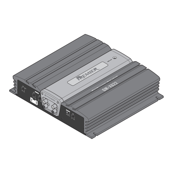
- Page 4 GM-X622,GM-X522 2.2 EXTERIOR Fig. 2...
- Page 5 GM-X622,GM-X522 NOTE: - Parts marked by “*”are generally unavailable because they are not in our Master Spare Parts List. - Screws adjacent to Ñ mark on the product are used for disassembly. (1) EXTERIOR SECTION PARTS LIST Mark No. Description Part No.
-
Page 6: Schematic Diagram
GM-X622,GM-X522 3. SCHEMATIC DIAGRAM 3.1 OVERALL CONNECTION DIAGRAM(GUIDE PAGE) Note: When ordering service parts, be sure to refer to “EXPLODED VIEWS AND PARTS LIST” or “ELECTRICAL PARTS LIST”. Large size SCH diagram Guide page SPEAKER INPUT VR101:FREQUENCY S101:LPF/HPF ISOLATOR INPUT Detailed page 20K(E) 20K(E) - Page 7 GM-X622,GM-X522 S451:BASS BOOST POWER AMP VR451:BASS BOOST LEVEL VR452:BASS BOOST fc VR453:GAIN BASS BOOST THERMO DETECTOR / PROTECTOR SWITCHING OVER VOLTAGE DETECTOR / PROTECTOR MUTE CONTROL CONTROL REGULATOR CONTROL Fig. 3...
- Page 8 GM-X622,GM-X522...
- Page 9 GM-X622,GM-X522 Fig. 4...
- Page 10 GM-X622,GM-X522...
- Page 11 GM-X622,GM-X522 Fig. 5...
-
Page 12: Pcb Connection Diagram
GM-X622,GM-X522 4. PCB CONNECTION DIAGRAM 4.1 AMP UNIT AMP UNIT NOTE FOR PCB DIAGRAMS 1. The parts mounted on this PCB include all necessary parts for several destination. For further information for respective destinations, be sure to check with the schematic diagram. - Page 13 GM-X622,GM-X522 SIDE A Fig. 8...
-
Page 14: Electrical Parts List
GM-X622,GM-X522 5. ELECTRICAL PARTS LIST NOTE: - Parts whose parts numbers are omitted are subject to being not supplied. - The part numbers shown below indicate chip components. Chip Resistor RS1/_S___J,RS1/__S___J Chip Capacitor (except for CQS..) CKS.., CCS.., CSZS..=====Circuit Symbol and No.===Part Name Part No. - Page 15 GM-X622,GM-X522 =====Circuit Symbol and No.===Part Name Part No. =====Circuit Symbol and No.===Part Name Part No. ------ ------------------------------------------ ------------------------- ------ ------------------------------------------ ------------------------- RD1/4PU103J RD1/4PU222J RD1/4PU472J RD1/4PU222J RD1/4PU472J RD1/4PU181J RD1/4PU562J RD1/4PU181J RD1/4PU562J RD1/4PU100J RD1/4PU103J RD1/4PU100J RD1/4PU103J RD1/4PU100J RD1/4PU123J RD1/4PU100J RD1/4PU123J 0.1½ CCN1082 RD1/4PU103J 0.1½...
- Page 16 GM-X622,GM-X522 =====Circuit Symbol and No.===Part Name Part No. =====Circuit Symbol and No.===Part Name Part No. ------ ------------------------------------------ ------------------------- ------ ------------------------------------------ ------------------------- RD1/4PU472J CFTLA104J50 RD1/4PU222J CFTLA104J50 RD1/4PU472J CEAS101M10 RD1/4PU472J CEAS101M10 RD1/4PU563J CCPUCH150J50 RD1/4PU563J CCPUCH150J50 RD1/4PU104J CMA330J2H RD1/4PU104J CMA330J2H RS1/2PMF220J CFTLA223J50 RD1/4PU153J CFTLA223J50 RS1/2PMF220J CFTLA333J50...
-
Page 17: Adjustment
GM-X622,GM-X522 CONTRAST TABLE of AMP UNIT GM-X622/X1R/EW, GM-X622/X1R/UC, GM-X622/X1R/ES and GM-X522/X1R/UC are constructed the same except for the following: Part No. Symbol and Description GM-X622/X1R/EW GM-X622/X1R/UC GM-X622/X1R/ES GM-X522/X1R/UC VR101 Not used CCS1251 Not used Not used VR452 Not used CCS1242 Not used Not used S451... -
Page 18: General Information
GM-X622,GM-X522 7. GENERAL INFORMATION 7.1 IC PA2027A Transient voltage detector Stby Bandgap DET1 Circuit motion:on DET2 Cont_V 50mA DET_R Filter 4.7k½ Bandgap:on Switch:on Vs_out 0.13V Mute_out 5.6V Oneshot (1msec) -
Page 19: Disassembly
GM-X622,GM-X522 7.2 DISASSEMBLY Panel Unit - Removing the Case and the Panel Units 1. Remove eight screws A and nine screws B. 2. Remove Case and Panel Units. Case Fig.7 Panel Unit - Removing the the Amp Unit Some silicone glue has been applied Amp Unit between the Heat Sink and the Sub Heat Sink. -
Page 20: Block Diagram
GM-X622,GM-X522 7.3 BLOCK DIAGRAM Fig. 8... -
Page 21: Operations And Specifications
GM-X622,GM-X522 8. OPERATIONS AND SPECIFICATIONS 8.1 SPECIFICATIONS Power source ......................14.4 V DC (10.8 — 15.1 V allowable) Grounding system ............................Negative type Current consumption ......................15.2 A (at continuous power, 4 W) Average current drawn* ......................4.6 A (4 W for two channels) 8.6 A (4 W for one channel) Fuse .................................... - Page 22 GM-X622,GM-X522 8.2 OPERATIONS...