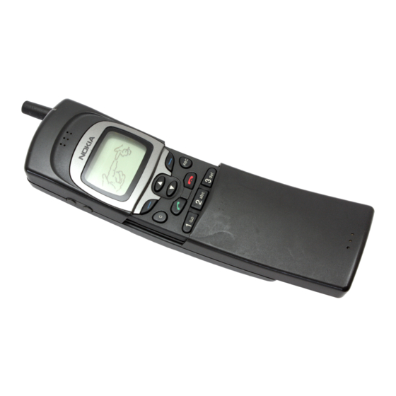
Nokia 8110 Installation Instructions Manual
Nhe–6 & nhk–6
Hide thumbs
Also See for 8110:
- User manual (40 pages) ,
- Troubleshooting manual (16 pages) ,
- Manual (37 pages)
Summary of Contents for Nokia 8110
- Page 1 After Sales Technical Documentation NHE–6 & NHK–6 INSTALLATION INSTRUCTIONS Original 18/96 NMP Part No. 0275214...
- Page 2 Installation Instructions After Sales Technical Documentation AMENDMENT RECORD SHEET Amendment Date Inserted By Comments Number Original 18/96 Page 2...
-
Page 3: Table Of Contents
After Sales Installation Instructions Technical Documentation NHE–6 & NHK–6 INSTALLATION INSTRUCTIONS Contents Introduction Page 4 General Page 4 Basic Car Kit (CARK–48) Page 5 Extended Car Kit (CARK–51) Page 6 Complete Car Kit (CARK–68) Page 7 Professional Car Kit (CARK–74) Page 8 Component Parts Page 9... -
Page 4: Introduction
Installation Instructions After Sales Technical Documentation Introduction General This installation guide has been prepared to provide the basic information nec- essary to install car kits. This guide is not intended to be definitive, because dif- ferent types and models of vehicle will require different installation work. The information given is for general guidance only. -
Page 5: Basic Car Kit (Cark-48)
After Sales Installation Instructions Technical Documentation Basic Car Kit (CARK–48) MBT–5 HHS–7 MKE–7 LCH–6 Product Name: Type: Code: Phone Holder MBT–5 0620030 Mounting Plate MKE–7 0650021 Swivel Mounting Plate HHS–7 0650020 Universal Mobile Charger LCH–6 0675076 Original 18/96 Page 5... -
Page 6: Extended Car Kit (Cark-51)
Installation Instructions After Sales Technical Documentation Extended Car Kit (CARK–51) MBT–5 HHS–7 MKE–7 XLC–1 AAH–1D PCM–5 LCM–1 PCC–2 For External Mobile Antenna (not supplied) Product Name: Type: Code: Phone Holder MBT–5 0620030 Mounting Plate MKE–7 0650021 Swivel Mounting Plate HHS–7 0650020 External Antenna Unit AAH–1D 0750077... -
Page 7: Complete Car Kit (Cark-68)
After Sales Installation Instructions Technical Documentation Complete Car Kit (CARK–68) PHF–3 MBT–5 HHS–7 MKE–7 For Power Cable PCH–4J HFM–7 AAH–1D For External Antenna (not supplied) Product Name: Type: Code: Phone Holder MBT–5 0620030 Standard Handsfree Unit PHF–3 0694030 Mounting Plate MKE–7 0650021 Swivel Mounting Plate... -
Page 8: Professional Car Kit (Cark-74)
Installation Instructions After Sales Technical Documentation Professional Car Kit (CARK–74) PHF–3 MBT–5 HHS–7 XHC–1 MKE–7 For Power Cable PCH–4J HFM–7 AAH–1D For External Antenna HFS–9 (not supplied) Product Name: Type: Code: Phone Holder MBT–5 0620030 Standard Handsfree Unit PHF–3 0694030 Mounting Plate MKE–7 0650021... -
Page 9: Component Parts
After Sales Installation Instructions Technical Documentation Component Parts Mounting Plate MKE–7 and Swivel Mounting Plate HHS–7 MKE–7 is a fixed position mounting plate; HHS–7 is a swivel mounting plate which allows for adjustable fixing. Both two mounting plates are interchange- able. -
Page 10: Fixed Mobile Charger Lcm-1
Installation Instructions After Sales Technical Documentation Fixed Mobile Charger LCM–1 The fixed mobile charger provides a power supply for the external antenna unit and the mobile phone. Output Power Cable PCC–2 The output power cable connects the fixed mobile charger to the external an- tenna unit. -
Page 11: Power Cable Pch-4J
After Sales Installation Instructions Technical Documentation Power Cable PCH–4J The power cable connects the standard handsfree unit, PHF–3, to the vehicle’s power supply. The red wire must be connected to the + voltage on the vehicle’s battery via the supplied fused connector. The black wire must be attached to a good negative GND connection. -
Page 12: Installation
Installation Instructions After Sales Technical Documentation Installation There are some important aspects that require special attention in positioning car kit accessories. The positioning of the phone holder is the most important factor when trying to achieve the most comfortable position for the user. The location of the holder should be selected so that the visibility of the phone’s display is good under all lighting conditions, but not so that the driver’s attention is easily distracted. - Page 13 After Sales Installation Instructions Technical Documentation After drilling the hole for the antenna remember to clean the hole from the dril- ling swarf, so that surface is even. This is needed in order to ensure proper and reliable connection between the ground plane and the antenna. After cleaning it is advised to apply some rust–proofing compound to the hole.
-
Page 14: Testing
Installation Instructions After Sales Technical Documentation Bosch P/N 0–332–204–150 12 V, 30 A. SPDT RADIO 12 V d.c. Supply for car radio 12 V d.c. To XCRM line (yellow wire) Fuse 200 mA (not supplied) Another possibility is to use a special muting unit, which mutes the radio by connecting load resistors to the speaker lines of the car radio. - Page 15 After Sales Installation Instructions Technical Documentation This page intentionally left blank. Original 18/96 Page 15...


