Table of Contents
Advertisement
Installation and Servicing
Instructions
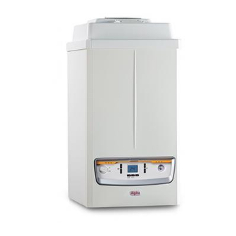
Alpha Pro Tec Plus 50, 70, 90 and 115
Wall Mounted, Fan Assisted, Gas Fired, High Efficiency
Condensing System Boilers
For Technical help or for Service call ...
ALPHA HELPLINE
Tel: 0870 3001964
Nepicar House, London Road,
Wrotham Heath, Sevenoaks,
Kent TN15 7RS
0051
Set for use with Natural Gas
Leave these instructions with the User
Advertisement
Table of Contents

Related Manuals for Alpha Pro Tec Plus 50


Summary of Contents for Alpha Pro Tec Plus 50
-
Page 1: Installation And Servicing
Installation and Servicing Instructions Alpha Pro Tec Plus 50, 70, 90 and 115 Wall Mounted, Fan Assisted, Gas Fired, High Efficiency Condensing System Boilers For Technical help or for Service call ... ALPHA HELPLINE Tel: 0870 3001964 Nepicar House, London Road,... - Page 2 Useful contact details: Gas Safe Register - 0800 408 5577 - www.gassaferegister.co.uk Alpha Heating Innovation: General Sales Enquiries - 0844 871 8760 Technical Helpline - 0844 871 8764 Alpha Pro Tec Plus 50, 70, 90, 115 - Benchmark Scheme...
-
Page 3: Table Of Contents
Fault finding ..........34 INTRODUCTION The Alpha Pro Tec Plus range are wall mounted high efficiency condensing, fan assisted system boilers. The burner is lit electronically and the heat output is controlled by a modulating fan and gas valve. These are system boilers providing heating only for sealed central heating systems. However, they may be used with an open central heating system if required - refer to Section 3.8. -
Page 4: General Data
1038 1038 Width Depth Clearances for servicing Bottom Top (horizontal flue) Top (vertical flue) Sides Front Boiler dry lift weight Boiler operating weight (full of water) approx. Water content litre Alpha Pro Tec Plus 50, 70, 90, 115 - Data... - Page 5 (factory set) 10.6 10.6 10.6 10.7 10.1 10.0 10.0 10.3 at minimum output (factory set) CO (nominal) at 0% O CO weight (nominal) mg/kWh Dry NOX weighted mg/kWh Alpha Pro Tec Plus 50, 70, 90, 115 - Data...
- Page 6 3. These dimensions only apply for flue parts supplied by Alpha. Cascade flue options are also available, please contact Alpha for further details. PUMP The boiler is equipped with a variable speed low power consumption pump.
- Page 7 Pro Tec Plus 70, 90 1000 1500 2000 2500 3000 3500 4000 4500 5000 5500 6000 6500 Flow rate (l/h) A = Available pump head B = Pump power com=nsumption (dotted area) Fig. 2.2 Alpha Pro Tec Plus 50, 70, 90, 115 - Data...
-
Page 8: Electrical Connections
Max. 1 A 220/240 V Cascade boiler External reset connections Open Therm 220/240 V Zone manager (1 to 6) Cascade Analog (optional) flow sensor input 0 - 10 V Fig. 2.4 Alpha Pro Tec Plus 50, 70, 90, 115 - Data... - Page 9 Flame sensing electrode Ignition electrode Primary flow sensor Combustion chamber cover Air inlet pipe Heat exchanger Burner Heat exchanger automatic air vent Venturi Flue sensor Automatic air vent Thermofuse Pump Fig. 2.5 Alpha Pro Tec Plus 50, 70, 90, 115 - Data...
- Page 10 Flue sensor Injector Burner Air inlet pipe Thermofuse Flame sensing electrode Ignition electrode Combustion chamber cover Manifold cover Heat exchanger Venturi Flue hood Pump Air sampling point Condensate trap Fig. 2.6 Alpha Pro Tec Plus 50, 70, 90, 115 - Data...
-
Page 11: General Boiler Information
Alpha Pro Tec Plus boilers leave the factory with 'B23' type flue configuration (open chamber and forced draught - single flue pipe). To change the configuration to 'C' type (sealed chamber and forced draught - concentric flue pipe), remove the 80 mm dia. - Page 12 90° bend is equivalent to 1.9 m of flue length 80 mm Open flue 30 m 28 m 14 m 8.5 m 45° bend is equivalent to 1.4 m of flue length Fig. 3.1 Alpha Pro Tec Plus 50, 70, 90, 115 - General Boiler Information...
- Page 13 Fig. 3.2 FLUE TERMINATION The Alpha Pro Tec Plus range of boilers can be individually flued using either 80 mm open flue configuration or 80/125 mm concentric flue. Multiple boilers can be individually flued or cascade flue kits are also available in 100 mm or 200 mm.
- Page 14 Figs. 3.4 and 3.5. The position for connecting an automatic make-up vessel is indicated in Fig. 3.3. A double check valve assembly must be used, as shown in Fig. 3.5. Alpha Pro Tec Plus 50, 70, 90, 115 - General Boiler Information...
- Page 15 3.10 FLUSHING THE HEATING SYSTEM It is essential that the central heating system is thoroughly cleaned and flushed when fitting an Alpha Pro Tec Plus boiler. Failure to do so will invalidate the warranty. If this is difficult because the system is old/dirty refer to Section 3.8, Fig. 3.3 gives consideration to using a barrier heat exchanger.
- Page 16 3.11 DISPOSAL OF CONDENSATE Provision must be made for the safe disposal of condensate produced by Alpha Pro Tec Plus boilers and reference should be made to BS 6798: 2000 for the requirements on the disposal of condensate. The boilers incorporate a condensate trap which has a seal greater than 75 mm, therefore no additional trap is required.
-
Page 17: Installation
80 Dia. E - Electrical connection G - Gas supply HR - Heating return HF - Heating flow CD - Condensate drain SV - Safety valve outlet (tundish) Fig. 4.1 Alpha Pro Tec Plus 50, 70, 90, 115 - Installation... - Page 18 MINIMUM BOTTOM CLEARANCE 250 mm Always grip the boiler firmly, and before lifting feel where the weight is concentrated to establish the centre of gravity, repositioning yourself as Fig. 4.3 necessary. Alpha Pro Tec Plus 50, 70, 90, 115 - Installation...
- Page 19 Note: To prevent condensate lying in the flue pipe, slope the pipe towards the boilers with a minimum slope of 2.5° - 3° (25 - 30 mm per metre). When installing the extensions, a wall/ceiling mounted clamp must be installed at least every 1.5 metres. Alpha Pro Tec Plus 50, 70, 90, 115 - Installation...
- Page 20 When installing the extensions, a wall/ceiling mounted clamp must be installed every 1.5 metres. Inner seal Flue elbow Outer seal Fixing plate Square gasket Concentric flue pipe Adapter Fig. 4.9 Alpha Pro Tec Plus 50, 70, 90, 115 - Installation...
- Page 21 Max. 1 A 220/240 V Cascade boiler External reset connections 220/240 V Open Therm Zone manager (1 to 6) Cascade Analog (optional) flow sensor input 0 - 10 V Fig. 4.11 Alpha Pro Tec Plus 50, 70, 90, 115 - Installation...
- Page 22 Fig. 4.12 Alpha Pro Tec Plus 50, 70, 90, 115 - Installation...
-
Page 23: Commissioning And Using The Boiler
If the front cover has not been removed, refer to Section 4.7. The Pro Tec Plus 50 has two automatic air vents (see Fig. 6.2), the Pro Tec Plus 70, 90, 115 boilers have one automatic air vent (see Fig. 6.3). Ensure that these are always open. - Page 24 Allow the boiler to run and heat the circuit, checking for leaks and correct circulation, testing any secondary circuits and zone controls for correct operation. During operation gas working pressure and gas rate checks can be conducted using the engineering function. Refer to Section 5.7. Alpha Pro Tec Plus 50, 70, 90, 115 - Commissioning...
- Page 25 Fig. 5.7 In the standby mode the boiler is still switched on but not active, maintaining the anti-freeze function. To turn it back on simply press button 'B'. RESET Fig. 5.8 Alpha Pro Tec Plus 50, 70, 90, 115 - Commissioning...
- Page 26 °C / °F Not used Flow temperature requested by system in heating °C / °F Flow temperature requested by system in DHW °C / °F Not used Not used Not used Alpha Pro Tec Plus 50, 70, 90, 115 - Commissioning...
- Page 27 Note: It is a requirement that the installation is registered by the installer through the Gas Safe Gas Work Notification Scheme. 12. Leave these Installation and Servicing instructions with the User for use on future calls. Alpha Pro Tec Plus 50, 70, 90, 115 - Commissioning...
-
Page 28: Routine Servicing
Check that the condensate trap drain pipe is connected and all joints are sound. Record details of the service in the Service Record Section at the back of this manual. Alpha Pro Tec Plus 50, 70, 90, 115 - Routine Servicing... - Page 29 (view 'A' in Fig. 6.1) Lower the panel out and away from the top cover. Note: If only the front panel is to be removed, remove as described in Section 4.7, paragraph 1. View A Fig. 6.1 (Pro Tec Plus 50 shown) Alpha Pro Tec Plus 50, 70, 90, 115 - Routine Servicing...
- Page 30 Place the case or front case panel in position and secure in position with the screws previously removed, see Section 6.2. Check the operation of the boiler. Return all controls to their original settings. Alpha Pro Tec Plus 50, 70, 90, 115 - Routine Servicing...
- Page 31 Flow manifold Flue sensor Safety valve 4 bar Automatic air vent Gas cock Test points (air A) - (flue F) Tundish Flue hood manifold Fig. 6.4 Pro Tec Plus 50 Alpha Pro Tec Plus 50, 70, 90, 115 - Routine Servicing...
- Page 32 Flue hood manifold Safety valve 4 bar Air intake pipe Ignition unit Test points (air A) - (flue F) Overheat thermostat (manual reset) Fig. 6.5 Pro Tec Plus 70, 90, 115 Alpha Pro Tec Plus 50, 70, 90, 115 - Routine Servicing...
-
Page 33: Wiring Diagram
M30 3-way valve motor (optional) M20 Fan Main switch System pressure switch (70, 90, 115 models only) S20 Room thermostat (optional) X40 Room thermostat jumper Gas valve Fig. 7.1 Alpha Pro Tec Plus 50, 70, 90, 115 - Wiring Diagram... -
Page 34: Fault Finding
Check return sensor resistance values. 0A80 Flow and return sensor connection fault. Check the wires are connected to the correct sensors. Fault may occur after several minutes of boiler operation. Alpha Pro Tec Plus 50, 70, 90, 115 - Fault Finding... - Page 35 This may occur if the main PCB or display PCB is changed. Check for correct parameter settings on PCB. Press '-' CH button until 'AUTO' appears, then press and hold 'RESET' button until 'bu1' appears. Alpha Pro Tec Plus 50, 70, 90, 115 - Fault Finding...
-
Page 36: Programming The Boiler Pcb
The boiler is supplied with the PCB configuration set according to the boiler model, however it is possible to adjust certain parameters according to the boiler and system configuration. Note: These parameters should only be adjusted by an approved Alpha engineer or Agent. To access the programming menu, press and hold buttons 'B' and 'C' simultaneously. - Page 37 0 - 10 V control feature (0 = temperature, 1 = heat output) CH sensor option 0 - 1 Pressure of CH sensor (0 = none, 1 = fitted) Alpha Pro Tec Plus 50, 70, 90, 115 - Programming the Boiler PCB...
-
Page 38: Performance Data
17.0 1.89 2240 15.0 1.68 2310 1.23 13.0 1.46 2080 1.07 2000 1.25 1840 0.91 1770 11.0 0.75 1530 1.03 1590 0.81 1350 0.59 1290 0.58 1100 0.43 1050 Alpha Pro Tec Plus 50, 70, 90, 115 - Performance Data... - Page 39 2120 1850 16.0 1.77 1950 1.30 1.55 1780 1.14 1680 14.0 1610 0.98 1510 12.0 1.33 1340 10.0 1.11 1440 0.82 0.89 1270 0.65 1170 1200 0.59 1100 0.80 Alpha Pro Tec Plus 50, 70, 90, 115 - Performance Data...
- Page 40 2030 24.0 2.62 2040 1.92 21.0 2.30 1850 1.68 1850 1670 1.45 1670 18.0 1.97 1.21 1490 15.0 1.64 1490 1310 12.0 1.32 1310 0.97 0.99 1150 0.73 1150 Alpha Pro Tec Plus 50, 70, 90, 115 - Performance Data...
- Page 41 1800 24.0 2.62 1860 1650 21.0 2.30 1710 1.69 1.97 1560 1.45 1500 18.0 1.21 1350 15.0 1.64 1400 1200 12.0 1.32 1250 0.97 1.21 1200 0.89 1150 11.0 Alpha Pro Tec Plus 50, 70, 90, 115 - Performance Data...
-
Page 42: Cascade System Installation
11 CASCADE SYSTEM INSTALLATION Alpha Pro Tec Plus 50, 70, 90, 115 - Cascade System Installation... -
Page 43: Short Parts Llist
3.025041 Air intake and flue circuit seal kit 3.025042 Gas circuit seal kit 3.025043 Heat exchanger seal kit 3.025044 Complete boiler seal kit 3.025045 Ignition electrode lead 1.035386 Alpha Pro Tec Plus 50, 70, 90, 115 - Short Parts List... -
Page 44: Energy Classification
(*) High temperature regime means 60°C return temperature at heater inlet and 80°C feed temperature at heater outlet. (**) Low temperature means for condensing boilers 30°C, for low-temperature boilers 37°C and for other heaters 50°C return temperature. Alpha Pro Tec Plus 50, 70, 90, 115 - Energy Classification... - Page 45 (*) High temperature regime means 60°C return temperature at heater inlet and 80°C feed temperature at heater outlet. (**) Low temperature means for condensing boilers 30°C, for low-temperature boilers 37°C and for other heaters 50°C return temperature. Alpha Pro Tec Plus 50, 70, 90, 115 - Energy Classification...
- Page 46 (AFC) Seasonal room heating yield (ηs) 92 % Seasonal room heating yield (ηs) 92 % Domestic hot water production yield (ηwh) ------- Domestic hot water production yield (ηwh) ------ Alpha Pro Tec Plus 50, 70, 90, 115 - Energy Classification...
- Page 47 Alpha Pro Tec Plus 50, 70, 90, 115 - Energy Classification...
- Page 48 Alpha Pro Tec Plus 50, 70, 90, 115 - Energy Classification...
- Page 49 Pro Tec Plus 50 Pro Tec Plus 70 Pro Tec Plus 90 Pro Tec Plus 115 ‘I’ ‘II’ ‘III’ 0.5445 0.3930 0.2969 0.2407 ‘IV’ 0.2090 0.1537 0.1112 0.0941 * To be established by means of table 5 of Regulation 811/2013 in case of “assembly” including a heat pump to integrate the boiler. In this case the boiler must be considered as the main appliance of the assembly. Alpha Pro Tec Plus 50, 70, 90, 115 - Energy Classification...
- Page 50 13.7 PARAMETERS FOR FILLING IN DHW PACKAGE ASSEMBLY CHART Parameter Pro Tec Plus 50 Pro Tec Plus 70 Pro Tec Plus 90 Pro Tec Plus 115 ‘I’ ‘II’ ‘III’ ‘IV’ * To be determined according to Regulation 811/2014 and transient calculation methods as per Notice of the European Community no. 207/2014. Alpha Pro Tec Plus 50, 70, 90, 115 - Energy Classification...
- Page 51 Alpha Pro Tec Plus 50, 70, 90, 115 - This Page Intentionally Blank...
-
Page 52: Benchmark Checklist
GAS BOILER SYSTEM COMMISSIONING CHECKLIST This Commissioning Checklist is to be completed in full by the competent person who commissioned the boiler as a means of demonstrating compliance with the appropriate Building Regulations and then handed to the customer to keep for future reference. Failure to install and commission according to the manufacturer’s instructions and complete this Benchmark Commissioning Checklist will invalidate the warranty. -
Page 53: Service Record
SERVICE RECORD It is recommended that your heating system is serviced regularly and that the appropriate Service Interval Record is completed. Service Provider Before completing the appropriate Service Record below, please ensure you have carried out the service as described in the manufacturer’s instructions. Always use the manufacturer’s specifed spare part when replacing controls. - Page 54 Alpha Pro Tec Plus 50, 70, 90, 115 - This Page Intentionally Blank...
- Page 55 Alpha Pro Tec Plus 50, 70, 90, 115 - This Page Intentionally Blank...
- Page 56 Alpha Therm Limited. These instructions have been carefully prepared but we reserve the right to Nepicar House, London Road, Wrotham Heath, alter the specification at any time in the interest of product improvement. Sevenoaks, Kent TN15 7RS © Alpha Therm Limited 2015. Tel: 0870 3001964 email: info@alphatherm.co.uk website:www.alpha-innovation.co.uk 1.038054 rev. ST.001455/000 Part No. Manual compiled and designed by Publications 2000 - Tel: (01670) 356211 04/15/D344...
Need help?
Do you have a question about the Pro Tec Plus 50 and is the answer not in the manual?
Questions and answers