Alpha E-Tec 28 Installation And Servicing Instruction
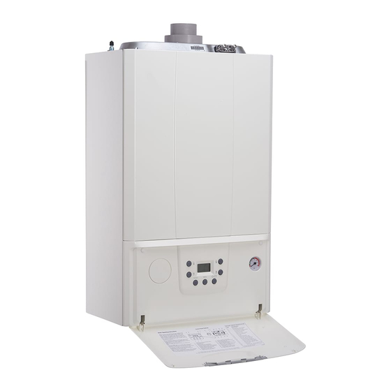
Wall mounted, fan assisted, room sealed, gas fired, high efficiency condensing combination boiler
Hide thumbs
Also See for E-Tec 28:
- User instructions (5 pages) ,
- Installation and servicing instruction (64 pages)
Advertisement
Table of Contents
- 1 Table of Contents
- 2 Introduction
- 3 Technical Data
- 4 General Boiler Information
- 5 Installation
- 6 Commissioning
- 7 Routine Servicing
- 8 Component Replacement
- 9 Wiring Diagram
- 10 Error Codes and Fault Finding
- 11 Short Parts List
- 12 Energy Classification
- 13 Benchmark Checklist
- 14 Service Record
- Download this manual
Installation and Servicing
Wall Mounted, Fan Assisted, Room Sealed,
Gas Fired, High Efficiency Condensing Combination Boiler
These instructions have been carefully prepared but we reserve the right
to alter the specification at any time in the interest of product improvement.
© Alpha Therm Limited 2017.
Instructions
E-Tec 28 and 33
For Technical help or for Service call ...
ALPHA HELPLINE Tel: 0844 871 8764
website: www.alpha-innovation.co.uk
Nepicar House, London Road,
Wrotham Heath, Sevenoaks,
Kent TN15 7RS
Set for use with Natural Gas
Leave these instructions with the User
Part No. 1.039255 rev. ST.002999.001
0317/D372
Advertisement
Table of Contents

Related Manuals for Alpha E-Tec 28


Summary of Contents for Alpha E-Tec 28
- Page 1 E-Tec 28 and 33 Wall Mounted, Fan Assisted, Room Sealed, Gas Fired, High Efficiency Condensing Combination Boiler For Technical help or for Service call ... ALPHA HELPLINE Tel: 0844 871 8764 website: www.alpha-innovation.co.uk Nepicar House, London Road, Wrotham Heath, Sevenoaks,...
- Page 2 Benchmark Service Interval Record and left with the householder. www.centralheating.co.uk Useful contact details: Gas Safe Register - 0800 408 5577 - www.gassaferegister.co.uk Alpha Heating Innovation: General Sales Enquiries - 0844 871 8760 Technical Helpline - 0844 871 8764 Alpha E-Tec 28 and 33 - Benchmark Scheme...
-
Page 3: Table Of Contents
Component replacement ....40 INTRODUCTION The E-Tec 28 and 33 are wall mounted, room sealed, fan assisted, high efficiency, condensing boilers. The burner is lit electronically and the heat output is controlled by a modulating fan and gas valve. The E-Tec 28 and 33 are combination boilers providing both central heating and domestic hot water at mains pressure. -
Page 4: Technical Data
DHW output 11.4 (±0.3) 11.2 (+0.2/-0.4) at minimum output 10.6 (±0.2) 10.0 (+0.4/-0.2) Gas rate at maximum output kg/h 2.24 2.53 Note: OtherTechnical data is the same as NG data. Alpha E-Tec 28 and 33 - Technical Data... - Page 5 Adjust using a flat head screwdriver, turn anticlockwise to close the by-pass, and clockwise to open. With the by-pass in the closed position the system must have a continuous open circuit. If zone valves are used in the system an external by-pass must be fitted. Alpha E-Tec 28 and 33 - Technical Data...
- Page 6 2.4.1 E-Tec 28 Available Pump Head and Power Consumption 1000 1200 1400 1600 Flow rate (l/h) A+B = Head available with by-pass closed B = Head available with by-pass open C+D = Power consumed by the pump with by-pass open (dotted area) D = Power consumed by the pump with by-pass closed (dotted area) Fig.
- Page 7 ELECTRICAL CONNECTIONS Note: This Appliance Must Be Earthed Optional integral single channel controls are available if required. Note: Only use the Alpha single channel controls. Do not fit any two channel controls. Programmer clock (optional) J2 on PCB X4 on PCB...
- Page 8 Safety valve indicator Condensate trap Burner Heating return isolation valve 3 bar safety valve Primary return sensor Heating flow isolation valve Expansion vessel Venturi positive pressure point (+) Automatic air vent Fig. 2.4 Alpha E-Tec 28 and 33 - Technical Data...
-
Page 9: General Boiler Information
2. Under no circumstances must the flue length (including allowances for extra bends) exceed 12 metres horizontally and only 14 metres vertically. 3. Failure to use Alpha flue components with the boiler will invalidate the boilers CE approval, guarantee and may be unsafe. - Page 10 L = A + (2 x 45° bends = 1.8 metre) Fig. 3.1 VERTICAL FLUE OPTIONS Not less than 300 mm Not less than 300 mm Hmax = 14 m Hmax = 12.2 m (14 m - 1.8 m) Fig. 3.2 Alpha E-Tec 28 and 33 - General Boiler Information...
- Page 11 Where a terminal is sited below 2 m from the ground or floor level, the terminal must be protected by a terminal guard. In these situations, consideration should also be given to prevent nuisance plume and fumes in areas such as access routes, passageways, patios, balconies etc. Alpha E-Tec 28 and 33 - General Boiler Information...
- Page 12 The boiler may be installed in a cupboard or compartment, provided it is correctly designed for that purpose, i.e. complies with the Building Regulations and the requirements of BS 6798. Alpha E-Tec 28 and 33 - General Boiler Information...
- Page 13 Drain taps (to BS 2879) must be used to allow the system to be completely drained. Hose Double check unions valve assembly Heating circuit Mains return water Stop Stop supply valve valve Test cock Filling loop temporarily connected Fig. 3.6 Alpha E-Tec 28 and 33 - General Boiler Information...
- Page 14 FLUSHING THE HEATING SYSTEM It is essential that the central heating system is thoroughly cleaned and flushed when fitting an Alpha boiler. Failure to do so will invalidate the warranty. The primary condensing heat exchanger is constructed in stainless steel and therefore is compatible with most materials used in a heating system.
- Page 15 Before the mains water supply pipe is connected to the boiler, it should be thoroughly flushed out to avoid the danger of dirt or foreign matter entering the boiler. Alpha E-Tec 28 and 33 - General Boiler Information...
-
Page 16: Installation
Condensate discharge pipe Literature pack and Wall template A suitable Alpha flue system must be selected to use with the boiler. Notes: a. All flues must be suitable for Alpha condensing boilers. b. CD 750 mm and 1000 mm flue extensions are available, if required. - Page 17 B - DHW outlet elbow - (15 mm) C - Cold water mains inlet - (15 mm) D - Heating return - (22 mm) E - Heating flow - (22 mm) Fig. 4.4 Alpha E-Tec 28 and 33 - Installation...
- Page 18 FIT THE FLUE - Figs. 4.5 and 4.6 The following procedure applies to fitting an Alpha CD Easy-Flue to both rear or side exit flue - horizontally only. The CD Easy-Flues are suitable for use in the flue length ranges shown in the tables below.
- Page 19 Note: Ensure that all cuts are square and free from burrs. Once assembled with the components pushed home, the flue is fully sealed. Allow 20 mm 30 mm Do not cut past this point Fig. 4.10 Alpha E-Tec 28 and 33 - Installation...
- Page 20 Use the template (supplied with the boiler) to mark the required flue position, ensure the slope towards the boiler is correct. Determine the overall flue length as described in Section 4.6, paragraph 2 to determine the number of Alpha CD 750 or 1000 mm flue extensions required.
- Page 21 Plume Management 1000 mm extension 60 mm dia. (equivalent to 1 m flue length) - Part No. 6.2001310. 60 mm dia. wall bracket - Part No. 6.2001260. Plume kit (2 x 93° bends 1 x 1000 mm extension and wall bracket) - Part No. 6.2001300. Fig. 4.12 Alpha E-Tec 28 and 33 - Installation...
- Page 22 Note: The equivalent horizontal flue assembly length + the equivalent plume management length (PM length) must not exceed the maximum flue length stated for each boiler, i.e. E-Tec boilers - the maximum equivalent flue length must not exceed 12 metres. Alpha E-Tec 28 and 33 - Installation...
- Page 23 It is recommended that Alpha controls are used with the boiler to maintain efficient and correct operation of the boiler. Please note that using controls that are not supplied or recommended by Alpha may invalidate the boiler warranty and may not control the boiler correctly.
- Page 24 Note: Before purchasing / installing Open Therm type controls from an alternative manufacturer, it is the installers responsibility to ensure they are compatible with the Alpha boiler. Remove the control panel as described in Section 4.10, if it has not already been removed.
-
Page 25: Commissioning
Loosen the gas inlet pressure test point screw on the gas valve (see Fig. 5.2) and purge in accordance with BS 6891. Retighten the test point screw and test for gas tightness. Close the boiler gas service cock. Alpha E-Tec 28 and 33 - Commissioning... - Page 26 The lighting mode can be varied via parameter 't8' in the PCB programming menu. For any controls fitted please refer to the instructions supplied with the controls for connection and operation details and Section 4.11. Alpha E-Tec 28 and 33 - Commissioning...
- Page 27 Pump Cycle If the electrical supply is on and the boiler has not operated for 24 hours in heating or hot water, the pump will operate automatically for thirty seconds every 24 hours. Alpha E-Tec 28 and 33 - Commissioning...
- Page 28 Explain to the User that in certain weather conditions the flue terminal will emit a plume of steam, i.e. water vapour. This is safe and quite normal. Show the User the position of the condensate discharge pipes. Alpha E-Tec 28 and 33 - Commissioning...
- Page 29 • After completing the conversion, apply the sticker (supplied in the conversion kit) near the boiler data plate. Using an indelible marker pen, delete the data relative to the old type of gas. These adjustments must be made according to the type of gas used, given in the table (Section 2). Alpha E-Tec 28 and 33- Commissioning...
- Page 30 Gas outlet flow Inlet pressure adjustment screw test point (Max. CO ) Off/Set adjustment screw (Min. CO ) Wiring plug Fig. 5.2 Fig. 5.3 Note: Min CO2 offset adjuster is behind a dust cap Alpha E-Tec 28 and 33 - Commissioning...
- Page 31 P0 - P5 ← RESET ← RESET ← RESET RESET + INFO (Without Parameter t0 - t9 → → memorising) value > 5 secs A0 - A6 S0 - S2 > 1 sec (Memorise) Alpha E-Tec 28 and 33 - Commissioning...
- Page 32 Remote control Section of the remote control communication protocol 0 - 1 0 - Alpha Climatic communication 1 - OpenTherm type remote control protocol setting Alpha E-Tec 28 and 33 - Commissioning...
- Page 33 0 Fixed - The switch-off temperature is fixed at the maximum value regardless of the value set on the control panel 1 Corrolated - The boiler switches off according to the temperature Alpha E-Tec 28 and 33 - Commissioning...
-
Page 34: Routine Servicing
Note: 1. Check the expansion vessel charge only when the system pressure is zero. 2. The expansion vessel pressure test point is accessible from on top at the top left side. Alpha E-Tec 28 and 33 - Routine Servicing... - Page 35 Take care not to damage the insulation on the back of the panel as this forms part of the casing room seal. Fig. 6.2 Alpha E-Tec 28 and 33 - Routine Servicing...
- Page 36 (view 'A' in Fig. 6.4) Lower the panel out and away from the top cover. Note: The side panels require no sealing strip as the front case insulation forms the room seal. View A Fig. 6.4 Alpha E-Tec 28 and 33 - Routine Servicing...
- Page 37 Check the condition of the burner injector in the gas valve outlet, carefully clean with a soft brush if necessary - Do not use a brush with metallic bristles as this might damage the injector. Unscrew and replace the injector should it appear damaged. Alpha E-Tec 28 and 33 - Routine Servicing...
- Page 38 DHW flow switch Automatic air vent Gas injector Boiler pump Gas valve 3 bar safety valve DHW heat exchanger By-pass Boiler drain point Diverter valve DHW temperature sensor Safety valve operation indicator Fig. 6.6 Alpha E-Tec 28 and 33 - Routine Servicing...
- Page 39 To ensure correct and safe operation of the appliance, it is essential that any worn or failed components are replaced with only genuine Alpha spare parts. Use of non-genuine Alpha spares could invalidate your warranty and may pose a potential safety hazard.
-
Page 40: Component Replacement
Unplug the wire from the flue sensor. Using a 13 mm spanner, turn the sensor 90° anti-clockwise and withdraw it from the heat exchanger. Fit the new sensor and re-assemble in reverse order. Alpha E-Tec 28 and 33 - Component Replacement... - Page 41 Lift out the trap being careful not to spill any condense water, remove the trap from the boiler. It is important to clean the trap every time the trap is removed to flush out any deposits from the collection bowl. Note: Partially fill the trap before replacing. Alpha E-Tec 28 and 33 - Component Replacement...
- Page 42 Remove the main cable grommet in the bottom panel and remove the sensor tube. Fit the new gauge sensor using a new 'O' ring on the connection if necessary. Reassemble in reverse order. Refill and pressurise the system. (Refer to Commissioning, Section 5.1). Alpha E-Tec 28 and 33 - Component Replacement...
- Page 43 Lift the motor upwards and forwards to remove from the valve body. Test the boiler in heating and hot water mode to ensure the motor is correctly engaged with the diverter valve spindle. Alpha E-Tec 28 and 33 - Component Replacement...
- Page 44 Fit the new panel(s) and re-assemble in reverse order referring to Routine Servicing, Section 6.5. Test the boiler, check the ignition and test the combustion as described in Section 6 7.25 ALPHA CONTROLS (if fitted) Refer to section 4.11 on the connection options for boiler controls. Alpha E-Tec 28 and 33 - Component Replacement...
-
Page 45: Wiring Diagram
-Vcc (optional) connect 220 V Climatic Control room thermostat (optional) When an Alpha Climatic control is connected to terminals 41 and 44 +Vcc remove the links between terminal blocks 1 and 2 Colour Code Component identification B1 ....Flow sensor Bk ..Black Bl ..Blue... -
Page 46: Error Codes And Fault Finding
Where an error code is displayed use the following tables to identify the fault and possible causes. ERROR CODES AND FAULT FINDING If any fault or anomaly persists, contact Alpha Heating Innovation Technical Helpline. The history of errors can be viewed in the 'INFO' menu - d9... - Page 47 Return/flow sensor Check sensor wiring and connections Check sensor resistance fault Return/flow sensor Possible failure of one or both sensors Check sensor wiring and connections fault Check sensor resistance Alpha E-Tec 28 and 33 - Error Codes and Fault Finding...
- Page 48 (i.e. 12 for one year). Save by pressing the mode button ( ) and wait for '88' to be displayed as confirmation. Alpha E-Tec 28 and 33 - Error Codes and Fault Finding...
-
Page 49: Short Parts List
Clip - Gas pipe connections 1.020393 Boiler wall bracket 2.015350 Boiler connection kit 3.024893 Boiler accessory box complete 3.026880 Wall template 1.039776 Burner front insulation panel 1.040668 Flue sensor 1.024296 Rear combustion insulation panel 1.040351 Alpha E-Tec 28 and 33 - Short Parts List... -
Page 50: Energy Classification
Contact details Alpha Therm Ltd., Nepicar House, Wrotham Heath, Kent. TN15 7RS (*) High temperature regime means 60°C return temperature at heater inlet and 80°C feed temperature at heater outlet. (**) Low temperature means for condensing boilers 30°C, for low-temperature boilers 37°C and for other heaters 50°C return temperature. - Page 51 (AFC) Seasonal room heating yield (ηs) 93 % Seasonal room heating yield (ηs) 93 % Domestic hot water production yield (ηwh) 87 % Domestic hot water production yield (ηwh) 87 % Alpha E-Tec 28 and 33 - Energy Classification...
- Page 52 Alpha E-Tec 28 and 33 - Energy Classification...
- Page 53 * To be established by means of table 5 of Regulation 811/2013 in case of “assembly” including a heat pump to integrate the boiler. In this case the boiler must be considered as the main appliance of the assembly. Alpha E-Tec 28 and 33 - Energy Classification...
- Page 54 11.7 PARAMETERS FOR FILLING IN DHW PACKAGE ASSEMBLY CHART Parameter E-Tec 28 E-Tec 33 ‘I’ ‘II’ ‘III’ * To be determined according to Regulation 811/2014 and transient calculation methods as per Notice of the European Community no. 207/2013. Alpha E-Tec 28 and 33 - Energy Classification...
- Page 55 Alpha E-Tec 28 and 33 - Energy Classification...
-
Page 56: Benchmark Checklist
GAS BOILER SYSTEM COMMISSIONING CHECKLIST This Commissioning Checklist is to be completed in full by the competent person who commissioned the boiler as a means of demonstrating compliance with the appropriate Building Regulations and then handed to the customer to keep for future reference. Failure to install and commission according to the manufacturer’s instructions and complete this Benchmark Commissioning Checklist will invalidate the warranty. -
Page 57: Service Record
SERVICE RECORD It is recommended that your heating system is serviced regularly and that the appropriate Service Interval Record is completed. Service Provider Before completing the appropriate Service Record below, please ensure you have carried out the service as described in the manufacturer’s instructions. Always use the manufacturer’s specifed spare part when replacing controls. - Page 58 Alpha E-Tec 28 and 33 - Page intentionally Blank...
- Page 59 Alpha E-Tec 28 and 33 - Page intentionally Blank...
Need help?
Do you have a question about the E-Tec 28 and is the answer not in the manual?
Questions and answers
What should the pressure read on Alpha Tec Plus 28 boiler?
The pressure on an Alpha E-Tec 28 boiler should be in the black area of the gauge when the boiler is operating. Additionally, the system pressure should not exceed 2.5 bar when the system is at operating temperature.
This answer is automatically generated