
Related Manuals for THERMOROSSI aspiromec le


Summary of Contents for THERMOROSSI aspiromec le
- Page 1 H E A T I N G T E C H N O L O G Y A N D I N N O V A T I O N INSTALLATION, USE AND MAINTENANCE GUIDE...
-
Page 3: Table Of Contents
....................4.14 Guidelines for the hydraulic connections of the ASPIROTRONIC COMBI LE boiler (Optional) ...... 4.15 Guidelines for the hydraulic connections of the ASPIROTRONIC LE / ASPIROMEC LE boiler with the boiler tube (optional) ..................................4.16 Example of hydraulic diagram for ASPIROTRONIC LE with DUO-TEC settings ............ -
Page 4: Ce Declaration Of Conformity
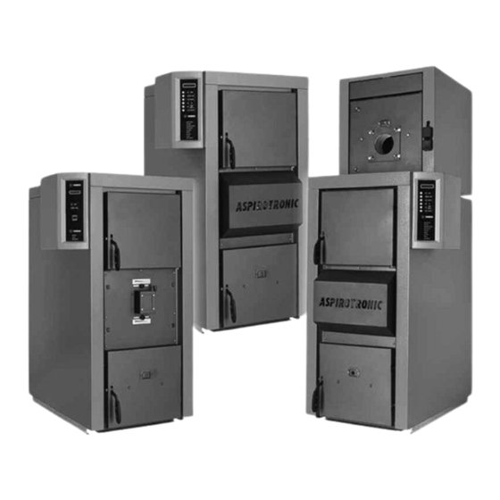
93/68/EEC 92/31/EEC 93/97/EEC Thermorossi S.p.A., Via Grumolo 4 - ARSIERO (VI), declares that the the boilers belonging to the series ASPIROMEC LE, ASPIROTRONIC LE, ASPIROTRONIC COMBI LE have been designed and manufactured in compliance with the safety requirements of the standards for EC marking. -
Page 5: Introduction
• If the appliance is sold or transferred to another user ensure that the guide is handed over with it. Thermorossi S.p.A. maintains the author’s rights on these service instructions. The information in this booklet may not be reproduced or given to third parties or used for competitive purposes without the appropriate authorization. -
Page 6: Standards And Recommendations
INTRODUCTION 1.3 STANDARDS AND RECOMMENDATIONS Normative references: national and international standards used for the design, industrialization and manufacture of the products described in this manual: – European Directive 73/23/EEC – CEI 61/50 – European Directive 93/68/EEC – CEI EN 60204 –... -
Page 7: Technical Characteristics
TECHNICAL CHARACTERISTICS TECHNICAL CHARACTERISTICS 2.1 TECHNICAL DATA ASPIROMEC LE ASPIROTRONIC LE ASPIROTRONIC COMBI LE page 7... - Page 8 LENGTH DRAFT LOSS LOSS REQUIRED CONTENT (l.) CONNECTIONS (kg) (bar) (mm) (mbar) (mbar) BY THE HEAT Ø EXCHANGER ASPIROMEC LE 35 -0,15 1/2" ASPIROMEC LE 54 -0,15 1/2" ASPIROMEC LE 73 -0,15 1/2" 1,96 ASPIROTRONIC LE 24 -0,15 1/2" 0,15...
- Page 9 4 - ASH PAN. The ash is deposited here. 5 - SAFETY HEAT EXCHANGER. ASPIROMEC LE and ASPIROTRONIC LE can be fitted with a safety heat exchanger. If a thermal relief valve is installed it absorbs the excess heat as soon as the boiler, due to external causes, increases to excessively high temperature values.
-
Page 10: Installation
INSTALLATION 4. INSTALLATION 4.1 MOUNTING THE OUTER CASING ON ASPIROTRONIC LE / ASPIROMEC LE. Key to outer casing material: 2 – Top front panel 3 – Top rear panel 4 – RH side panel (2 pieces for model 102) 5 – Support profiles 6 - Back 7 –... -
Page 11: Mounting The Outer Casing On Aspirotronic Combi Le
INSTALLATION 4.2 MOUNTING THE OUTER CASING ON ASPIROTRONIC COMBI LE. - Mount the outer casing to the boiler as shown in the figure on the previous page. - Do not mount the top front panel (2); in its place, mount the top rear panel (3) (For LE 102 COMBI use 2 brackets as the Eura boiler, unlike the Aspirotronic boiler, is positioned centrally). -
Page 12: Mounting The Electronic Panel On Aspirotronic Le
INSTALLATION 4.3 MOUNTING THE ELECTRONIC PANEL ON ASPIROTRONIC LE 1- Cage nuts 2- Screws M5x16 3- Control board 4- Board cover 5- Self-tapping screws - Fasten the ASPIROTRONIC panel to the left side panel of the boiler. (If mounting it on the right side panel, fix the control board by rotating it by 180°... -
Page 13: Functions Of Panel On Aspirotronic Le
INSTALLATION 4.4 FUNCTIONS OF PANEL ON ASPIROTRONIC LE The electronic panel is managed by a suitably programmed microprocessor. The microprocessor not only improves the functioning of the boiler, but it also makes it possible to manage the gas-diesel oil boiler with blown burner of the EURA series. -
Page 14: Display Panel Of Aspirotronic
DISPLAY settings for the dipswitches located on the front panel are shown below (figure below). Prog. Boiler Prog. Boiler ASPIROTRONIC LE ASPIROMEC LE CONNECTION 2 WIRES BOILER TUBE THERMOCOUPLE Prog. Boiler Prog. Boiler BOILER TUBE CONNECTION 2 WIRES DIESEL OIL THERMOCOUPLE... -
Page 15: Electrical Connections Diagram For Aspirotronic Le
INSTALLATION 4.7 ELECTRICAL CONNECTIONS DIAGRAM FOR ASPIROTRONIC LE The circuitry consists of 3 terminal boards called M1 M2 M3. The individual contacts are called "pins". TERMINAL BOARD M1 Pins 1-2-3 are used in the combi version with the installation of a 3-way motorised valve which can cut out and isolate the wood fuel boiler when the gas-diesel oil boiler is operating. -
Page 16: Diagram Of Aspirotronic Le Electronic Panel
INSTALLATION 4.7.1 DIAGRAM OF ASPIROTRONIC LE ELECTRONIC PANEL 1 1 1 1 3 WAY VALVE DIESEL OIL POSITION 2 2 2 2 3 WAY VALVE WOOD POSITION COMMON 3 WAY VALVE ROOM TEMPERATURE THERMOSTAT 3 3 3 3 6 6 6 6 PLANT CIRCULATING PUMP 4 4 4 4 COMMON BOILER TUBE THERMOSTAT... -
Page 17: Remote Board Control
INSTALLATION 4.7.2 REMOTE BOARD CONTROL Allows you to view the main parameters of the generator on a separate unit (Remote Board Control). The data is transmitted on radio waves. The unit is powered with the help of a transformer 220 – 7.5 V (supplied). 4.7.3 INSTALLATION OF THE ANTENNA Installation of the antenna on the control board for the "Remote Board Control"... -
Page 18: Installation Of Aspiromec Le Electromechanical Panel
4 – Board cover 5 – Self-tapping screws Fasten the ASPIROMEC LE panel to the front cover of the boiler. Use the supplied screws and nuts (3) to fasten the panel with cover after having made all the necessary connections: unwind the capillaries, thread them through the precut holes in the side right or left, insert the end bulbs in the pockets (A) located on the top of the boiler and fill up with lubricating oil to improve the exchange. -
Page 19: Aspiromec Le Electromechanical Panel Functions
INSTALLATION 4.9 ASPIROMEC LE ELECTROMECHANICAL PANEL FUNCTIONS The control panel consists of the following parts: 1 – Main and cycle start switch (illuminated). 2 – Boiler fan control switch. 3 – Heating plant circulating pump control switch. 4 – Wood cycle start and fuel finished signal light. This light comes on when the fuel finished thermostat signals a drop in the water temperature caused by a lack of firewood. -
Page 20: Wiring Diagram For Aspiromec Le
INSTALLATION 4.9.1 WIRING DIAGRAM FOR ASPIROMEC LE TERMINAL BOARD X1 page 20... -
Page 21: Electrical Connections Diagram For Aspiromec Le
60° C. 4.11 INSTALLATION OF SMOKE SUCTION UNIT ON ASPIROMEC LE / ASPIROTRONIC LE Install the smoke suction unit after mounting the outer casing. -
Page 22: Installation Of Safety Exchanger/Heat Exchanger On Aspiromec Le/Aspirotronic Le (Optional)
INSTALLATION 4.12 INSTALLATION OF SAFETY EXCHANGER / HEAT EXCHANGER ON ASPIROMEC LE ASPIROTRONIC LE (OPTIONAL). 1 SAFETY EXCHANGER / HEAT EXCHANGER 2 SCREWS AND NUTS FOR FASTENING EXCHANGER INLET-OUTLET 3 COVER Remove the precut covers from the exchanger holes on the side panels of the outer casing;... -
Page 23: Guidelines For The Hydraulic Connections Of The Aspirotronic Combi Le Boiler (Optional)
VST: Thermal relief valve VS: Safety valve 4.15 GUIDELINES FOR THE HYDRAULIC CONNECTIONS OF THE ASPIROTRONIC LE ASPIROMEC LE BOILER WITH BOILER TUBE (OPTIONAL) The connections to be made are shown in the following diagram: Heating system delivery Heating system return... -
Page 24: Example Of Hydraulic Diagram For Aspirotronic Le With Duo-Tec Settings
INSTALLATION 4.16 EXAMPLE OF HYDRAULIC DIAGRAM FOR ASPIROTRONIC LE WITH DUO-TEC SETTINGS Pump Radiators Expansion tank preloaded at 1.5 bar Open expansion tank Heat exchanger (e.g: plate-type exchanger) Safety tube that connects the boiler to the open expansion tank Boiler drain PC: Plant circulating pump On-off valve VNR: Nonreturn valve... -
Page 25: Approximate Hydraulic Diagram Of Aspirotronic Le With Puffer With First Priority To Heating System
CAUTION: For the management of the electronic panel with this type of plant contact an authorised Thermorossi service centre. The approximate diagram shows an example of how the puffer can be installed in the plant. It operates as follows: The plant must be equipped with 2 additional feelers installed on the puffer as well as the one already installed on the Aspirotronic panel to be inserted in the pocket on the wood-fired boiler. -
Page 26: Starting The Aspiromec Le Boiler
USE OF THE BOILER 5. USE OF THE BOILER 5.1 STARTING THE ASPIROMEC LE BOILER Arrange roughly cut pieces of dry wood (D. 3-4cm) on the central part of the burner; then place thinner wood on top of this, lastly place a fair amount of newspaper on top of this wood and light it. -
Page 27: Refuelling With Wood
USE OF THE BOILER 5.3 REGULATION OF COMBUSTION AIRS IN ASPIROMEC LE AND ASPIROTRONIC LE To regulate the airs firstly remove the guard with the writing ASPIRO- TRONIC on it (there is no guard on the ASPIROMEC model). 1- Act on damper 1 to regulate the intake of primary combustion air. -
Page 28: Practical Advice And Guidelines
USE OF THE BOILER 5.6 PRACTICAL ADVICE AND GUIDELINES The load of wood must always be suitable for the actual technical absorption requirements of the plant: large load of wood in conditions of limited plant absorption result in long periods of unburned wood lying on top of a layer of embers. -
Page 29: Troubleshooting
TROUBLESHOOTING 6 TROUBLESHOOTING 6.1 TROUBLESHOOTING FOR ASPIROTRONIC LE AND ASPIROMEC LE BOILERS Burner blocked Clean the burner by lifting the plate Use more seasoned and smaller Moist wood or too thick pieces of wood Difficulty with the first start up... -
Page 30: Cleaning And Maintenance
SCOVOLO CLEANING AND MAINTENANCE 7 CLEANING AND MAINTENANCE 7.1 CLEANING AND MAINTAINING ASPIROTRONIC LE AND ASPIROMEC LE BOILERS SCOVOLO FIGURA B pag. 5 FIGURA C (LE 24) FIGURA A (LE 35-54-73-102) The LE series boilers must be cleaned in accordance with the following time schedule: EVERY 3 days remove all ash from the compartment using the special tool (figure B) to de-ash the cast iron pan. - Page 31 NOTES page 31...
Need help?
Do you have a question about the aspiromec le and is the answer not in the manual?
Questions and answers