
Related Manuals for THERMOROSSI Ecotherm H2O


Summary of Contents for THERMOROSSI Ecotherm H2O
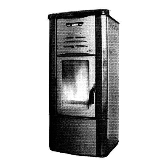
- Page 1 T E C N O L O G I E E D I N N O V A Z I O N I P E R I L R I S C A L D A M E N T O INSTALLATION, USE AND MAINTENANCE GUIDE Ecotherm H O pellet heater...
-
Page 3: Table Of Contents
CONTENTS CONTENTS DECLARATION OF CONFORMITY ............................ 1. INTRODUCTION ................................1.1 General guidelines ............................... 1.2 Safety guidelines ................................1.3 Standards and recommendations ..........................1.4 Transportation and storage ............................2. TECHNICAL CHARACTERISTICS ..........................2.1 Technical data 3. GENERAL DESCRIPTION 3.1 Operating technology ..............................3.2 Pellets ................................... - Page 4 93/68/EEC 92/31/EEC 93/97/EEC Thermorossi S.p.A., Via Grumolo 4 - ARSIERO (VI), declares that the H2O appliance and the Compact boiler have been designed and manufactured in compliance with the safety requirements of the standards for EC marking. This declaration refers to the entire range of the specified series.
-
Page 5: Introduction
• If the appliance is sold or transferred to another user ensure that the guide is handed over with it. Thermorossi S.p.A. maintains the authorʼs rights on these service instructions. The information in this booklet may not be reproduced or given to third parties or used for competitive purposes without the appropriate authorization. -
Page 6: Standards And Recommendations
INTRODUCTION 1.3 STANDARDS AND RECOMMENDATIONS Normative references: national and international standards used for the design, industrialization and manufacture of the products described in this manual: – European Directive 73/23/EEC – CEI 61/50 – European Directive 93/68/EEC – CEI EN 60204 –... -
Page 7: Technical Characteristics
TECHNICAL CHARACTERISTICS 2. TECHNICAL CHARACTERISTICS 2.1 TECHNICAL DATA Height (mm) Depth (mm) Width (mm) Weight (kg) Smoke Temp. min – max (C) ø smoke outlet tube (mm) ø combustion air tube (mm) Minimum draft (mbar) Heat efficiency (kW) Air output power (kW) Water output power (kW) Efficiency Min/max consumption (kg/h) -
Page 8: General Description
GENERAL DESCRIPTION 3. GENERAL DESCRIPTION 3.1 OPERATING TECHNOLOGY Your heater/boiler has been built to fully satisfy all your heating and practical requirements. Top-grade components and functions managed with microprocessor technology guarantee high reliability and optimal performance. 3.2 PELLETS • The heater is fuelled by pellets, that is, cylinders of compressed sawdust; this allows you to fully enjoy the heat of the flame without having to manually stoke the combustion. -
Page 9: Main Components Of The H2O Heater And Compact Boiler
GENERAL DESCRIPTION 3.4 MAIN COMPONENTS OF THE H2O HEATER AND COMPACT BOILER A: BRAZIER CLEANER MOTOR AUTOMATIC RELIEF VALVE SYSTEM CIRCULATING PUMP Q: INSPECTION COVER FOR TUBE BUNDLE SMOKE SUCTION UNIT CONTROL PANEL D: SMOKE OUTLET TUBE SPIRAL TUBE SCRAPER LEVER COMBUSTION AIR EXHAUST TUBE ASH PANS SMOKE SIDE PRESSURE SWITCH... -
Page 10: Installation
INSTALLAZIONE INSTALLATION 4. INSTALLATION 4.1 HEATER/BOILER LOCATION CAUTION: Use trolleys to move the appliance and always keep it in a vertical position. To unpack it, after having removed the wooden crate, remove the casing (in the reverse order than described in par. -
Page 11: How To Mount The H2O Heater Casing
INSTALLAZIONE INSTALLATION 4.2.1 HOW TO MOUNT THE H2O HEATER CASING Once the heater has been positioned and levelled by raising or lowering the mounting feet, and connected to the heating system and the electrical system (see par. 4.5, 4.7, 4.8, 4.9, 4.10, 4.11), the next step is to mount the casing as illustrated in the figure below: - Firstly mount the 2 side panels by centring the bottom folds on the holes of the base and tightening the 2 top screws with a screwdriver. -
Page 12: How To Install An Additional Compact Boiler Tank (Optional)
INSTALLATION 4.2.3 HOW TO INSTALL AN ADDITIONAL COMPACT BOILER TANK (OPTIONAL) To increase the boilerʼs autonomy of operation it is possible to install one or two additional tanks at the sides of the boiler. Each tank can hold up to 100 Kg of pellets. Firstly unpack the tank then assemble it: - Fasten the 4 telescopic legs (A) using the screws provided (screws TSP+ 8x50). -
Page 13: How To Fit The Additional Tank (Optional) With The Compact Boiler
INSTALLATION 4.2.2 HOW TO FIT THE ADDITIONAL TANK (OPTIONAL) WITH THE COMPACT BOILER After having mounted the additional tank assemble the tank and boiler: - Remove the octagonal portion of precut sheet metal from the side (F) of the boiler . - Remove the cap (I) from the tank by undoing the 4 screws. - Page 14 INSTALLATION 1 - Appliance start up and shut down button. Press this button to position the appliance (6) on START or OFF. When it is pressed repeatedly up to 5 LEDs (4) come on and the indicator A (4; automatic) is activated. The following texts could appear on the display: “...
-
Page 15: Description Of The Automatic Mode Cycle
INSTALLATION 4.3.1 DESCRIPTION OF THE AUTOMATIC MODE CYCLE When the letter A appears on the display it indicates that the Automatic cycle has been selected. In the Automatic cycle the appliance expresses its maximum operating flexibility by optimizing the fuel consumption. If, for example, the temperature is set (7) at 70 °C the five speed ratios will be automatically distributed between 61 and 70°C so that when the temperature reaches 70°C the appliance will be running at the minimum power. -
Page 16: Control, Adjustment And Programming Functions Of The H2O/Compact Control Panel
INSTALLATION 4.4 CONTROL, ADJUSTMENT AND PROGRAMMING FUNCTIONS OF THE H 0/COMPACT CONTROL PANEL 4.4.1 SETTING THE OPERATING PROGRAMS P1 AND P2 Your appliance is provided with an excellent operating program to enhance combustion efficiency. The particular configuration of the burner keeps the area where the pellets drop and burn clean for many hours. However, if you wish to keep the burner even cleaner simply select the P2 operating cycle which emits a larger quantity of air into the brazier. -
Page 17: Controlling The Pressure Of The Water In The Boiler
INSTALLATION Press the button to set the current hour (e.g. 10). Then press the button to confirm. The following graphic image will appear on the display: Press the button to set the minutes (e.g. 10:35). Then press the button to confirm and quit the current time and day setting menu. -
Page 18: Weekly Programming
INSTALLATION 4.4.4 WEEKLY PROGRAMMING The H20 appliance and Compact boiler can be programmed for a week with up to 2 on-off cycles for each day from Monday to Sunday. When the appliance is running in programmed mode ( symbol active) the appliance self-adjusts its combustion power according to the automatic cycle (see par. - Page 19 INSTALLATION Press the button and/or the button to set the hour for the appliance to stop for the first time during the day on Monday (e.g. 11.00 am). Then press the button to confirm. The following graphic image will appear on the display: Press the button and/or the...
- Page 20 INSTALLATION It is possible to activate or deactivate the programming for the entire week by pressing the button when the heater is in OFF mode. Press this button to activate ( symbol appears) or deactivate ( symbol does not appear) the programming.
- Page 21 INSTALLATION 4.5 H O/COMPACT POWER BOARD DIAGRAM Receiver Code selector for room board temperature thermostat managed by radio waves Fuse 3.15 A 220-240 V 50 Hz Smoke exhaust Burner motor Thermostat 100°C reset Pellet feed motor Heating element Common n.o. (normally open) Motorised boiler tube SV valve circulating pump Plant circulating...
- Page 22 INSTALLATION It is furthermore necessary to place the room temperature thermostat at a maximum of 10 metres from the appliance as if the distance is too great and there are too many walls located between the room temperature thermostat and the appliance, this can affect the functioning of the thermostat. In order for the room temperature thermostat to function correctly it is important for the “code system”...
- Page 23 INSTALLATION 4.8 EXAMPLE OF HYDRAULIC DIAGRAM FOR H O HEATER/COMPACT ONLY HEATING A: Heating system delivery R: Heating system return S: gate valve VNR: non-return valve VEC: expansion tank closed to protect system VR: pressure reduction valve From water supply system for replenishment Drain 4.8 EXAMPLE OF HYDRAULIC DIAGRAM FOR H...
- Page 24 INSTALLATION 4.10 EXAMPLE OF HYDRAULIC DIAGRAM FOR H 0 HEATER/COMPACT WITH BOILER TUBE COILS A: Heating system delivery R: Heating system return S: gate valve VNR: non-return valve VEC: expansion tank closed to protect system From water supply VM3V: 3-way motor-operated valve with spring return Drain system for replenishment VR: pressure reduction valve...
-
Page 25: Use Of The Heater/Boiler
USE OF THE HEATER/BOILER 5. USE OF THE HEATER/BOILER 5.1 SWITCHING ON THE H 0 HEATER/COMPACT BOILER Before using the appliance check that all the movable parts are in place; also remove any labels and stickers from the glass to avoid having permanent traces remain on the surfaces. Ensure that the electrical and hydraulic connections have been made perfectly. -
Page 26: Adjusting The Combustion Of The H2O Heater/Compact Boiler
USE OF THE HEATER/BOILER 5.2 ADJUSTING THE COMBUSTION OF THE H2O HEATER/ COMPACT BOILER The thermal value is adjusted by means of the 2 buttons “A” and “B” indicated in the figure in the previous paragraph. 5.2.1 Manual adjustment of the combustion (see par. 4.3.2) 5.2.2 Automatic adjustment of the combustion (see par. -
Page 27: Cleaning And Maintenance
CLEANING AND MAINTENANCE 7. CLEANING AND MAINTENANCE 7.1 FOREWORD Before beginning any operation ensure that the appliance is in the “OFF” mode, by disconnecting the electrical power plug. Your appliance does not require any special maintenance; keep to the simple, basic but frequent general control and cleaning operations. - Page 28 CLEANING AND MAINTENANCE A vacuum cleaner simplifies the ash removal process. Clean the glass with a damp cloth or a damp ball of newspaper dipped in ash and wipe the glass until it is perfectly clean. Do not clean the glass while the appliance is in operation.
-
Page 29: Patented Self-Cleaning Burner
CLEANING AND MAINTENANCE 7.3 PATENDED SELF-CLEANING BURNER (NR. VI2004A000014) 1 - flame deflector blade The H O heater/Compact boiler is fitted with a 2 - cast iron rear burner chute state of the art patented burner which manages 3 - cast iron front burner chute to guarantee high performance with optimal 4 - catalyst paddle automatic cleanliness of the burner due to the... -
Page 30: Combustion Air Suction
SMOKE VENT AND COMBUSTION AIR SUCTION • Air used for combustion is sucked in through a tube installed at the back of the appliance. It has a diameter of 80 mm. • The air flow can also be obtained from an adjacent room as long as: - the adjacent room is equipped with direct ventilation in compliance with the points described above;... -
Page 31: Smoke Outlet
SMOKE VENT AND COMBUSTION AIR SUCTION 8.2 SMOKE OUTLET The smoke outlet shown in the following figures is the best solution to ensure the discharge of smoke even when the fan is not operational, such as for example if there is an electrical power failure. A minimum drop of 1.5 metres is required between the T terminal on the outside of the building and the outlet at the back of the appliance, to ensure that residual combustion smoke is discharged in the case described above (Otherwise the residues would stagnate inside the firebox and be discharged out to the free atmosphere). -
Page 32: Information For The Skilled Technician
INFORMATION FOR THE SKILLED TECHNICIAN 9. INFORMATION FOR THE SKILLED TECHNICIAN 9.1 MAIN COMPONENTS AND THEIR OPERATION SAFETY THERMOSTAT WITH MANUAL RESET: if the temperature exceeds 100°C the pellet feed screw is shut off. A red light at the back of the appliance comes on. Once the reasons for the appliance exceeding the upper temperature limit have been discovered and solved the heater can be reactivated by unscrewing the plastic cover of the thermostat installed on the back and pressing the button (the temperature of the boiler must be below 73°C). -
Page 33: Troubleshooting
INSTALLATION 9.2 TROUBLESHOOTING problem cause solution Pellet tank is empty Fill up the tank Foreign body such as nail, nylon, piece of wood on the feeder screw on the Remove the foreign body bottom of the tank Check the smoke exhaust as it could be “PGAS”... - Page 34 NOTES page 34...
- Page 35 NOTES page 35...
- Page 36 36011 Arsiero (VI) - Via Grumolo, 4 Z.I. - Tel. 0445.741310 (5 l.r.a.) - Fax 0445.741657 Web Site: www.thermorossi.com...
Need help?
Do you have a question about the Ecotherm H2O and is the answer not in the manual?
Questions and answers