Hitachi C 10FL Instruction Manual And Safety Instructions
Hide thumbs
Also See for C 10FL:
- Instruction manual (32 pages) ,
- Instruction manual (32 pages) ,
- Instruction manual and safety instructions (80 pages)
Table of Contents
Advertisement
Quick Links
Model
INSTRUCTION MANUAL AND SAFETY INSTRUCTIONS
Improper and unsafe use of this power tool can result in death or serious bodily injury!
This manual contains important information about product safety. Please read and understand this manual
before operating the power tool. Please keep this manual available for others before they use the power
tool.
N136
C 10FL
WARNING
– 1 –
Stationary Table Saw
Hitachi Koki
English
Advertisement
Table of Contents

Related Manuals for Hitachi C 10FL


Summary of Contents for Hitachi C 10FL
- Page 1 English Model C 10FL Stationary Table Saw INSTRUCTION MANUAL AND SAFETY INSTRUCTIONS WARNING Improper and unsafe use of this power tool can result in death or serious bodily injury! This manual contains important information about product safety. Please read and understand this manual before operating the power tool.
-
Page 2: Table Of Contents
English CONTENTS English SECTION PAGE SECTION PAGE Product Specifications ........Know Your Stationary Table Saw ......Power Tool Safety ..........Glossary of Terms ..........Table Saw Safety ..........Assembly and Adjustments ......... Electrical Requirements and Safety ....Operation ............Accessories and Attachments ......Maintenance ............ -
Page 3: Product Specifications
English WARNING Some dust created by power sanding, sawing, grinding, drilling and other construction activities contains chemicals (known to the State of California) to cause cancer, birth defects or other reproductive harm. Some examples of these chemicals are: • Lead based paints •... -
Page 4: Power Tool Safety
English POWER TOOL SAFETY WARNING Before using your table saw, it is critical that you read and understand these safety rules. Failure to follow these rules could result in serious injury or damage to the table saw. Good safety practices are a combination of common accessories. -
Page 5: Table Saw Safety
English TABLE SAW SAFETY 1. ALWAYS USE SAW BLADE GUARD, splitter 12. PROVIDE ADEQUATE SUPPORT to the rear and anti-kickback pawls for every through–sawing and the sides of the saw table for long or wide operation. Through–sawing operations are those workpieces. -
Page 6: Electrical Requirements And Safety
English ELECTRICAL REQUIREMENTS AND SAFETY CONNECTING TO THE POWER SUPPLY Check that the power supply and plug used is in accordance with your drill press. Have a look at the rating plate of the motor or the rating on the drill press. Any changes should always be carried out by a qualified electrician. WARNING This machine must be earthed. -
Page 7: Accessories And Attachments
English ACCESSORIES AND ATTACHMENTS RECOMMENDED ACCESSORIES WARNING WARNING To avoid the risk of personal injury: • Do not use a dado with a diameter larger than 8” Visit your Hardware Department or see the Power (203.2mm). and Hand Tools Catalog to purchase recommended •... -
Page 8: Carton Contents
English CARTON CONTENTS UNPACKING AND CHECKING CONTENTS WARNING Separate all parts from packing materials. Check each If any part is missing or damaged, do not attempt part with the illustration on the next page and the “Table to assemble the table saw, plug in the power cord, of Loose Parts”... - Page 9 English UNPACKING YOUR STATIONARY TABLE SAW – 9 –...
-
Page 10: Know Your Stationary Table Saw
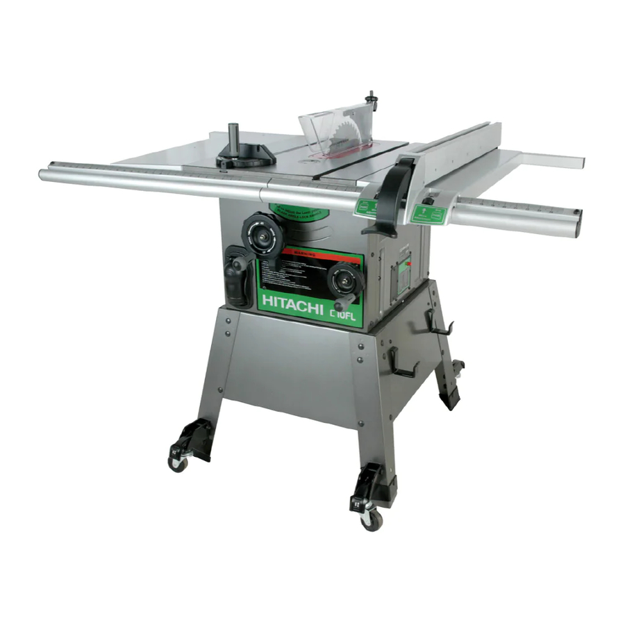
English KNOW YOUR STATIONARY TABLE SAW Rip Fence Blade guard Blade Tilt Scale Miter Gauge Table Extension (Left) Table Extension (Right) Blade elevation handwheel Blade Tilting Handwheel ON/OFF switch with key Power cord storage Stand Caster Table Insert Splitter Table Miter Gauge Storage Rip Fence Storage –... -
Page 11: Glossary Of Terms
English GLOSSARY OF TERMS HITACHI PROFESSIONAL FREEHAND – Performing a cut without using a fence TABLE SAW TERMS (guide), hold down or other proper device to prevent the workpiece from twisting during the cutting operation. MITER GAUGE – A guide used for crosscutting operations that slides in the tabletop channels located GUM –... -
Page 12: Assembly And Adjustments
English ASSEMBLY AND ADJUSTMENTS ESTIMATED ASSEMBLY TIME 50~70 MINUTES (2 ASSEMBLE TABLE SAW TO STAND (FIG. A, B) PEOPLE) 1. Place protective corrugated cardboard or old blanket ASSEMBLE STAND (FIG. A) on floor to protect the saw table surface. 1. Unpack all parts and group by type and size. Refer 2. - Page 13 English ASSEMBLY THE TABLE EXTENSION (FIG. C) Assembly the rear table rail (Fig. E) 1. Place the left table extension next to the saw 6. Attach the side covers (1) and middle plug (2) to the table, aligning the mounting holes (1). rear table rails (3).
- Page 14 English ALIGNING THE BLADE GUARD SPLITTER (FIG. H) Installing the blade guard assembly (Fig. G) 1. Remove the table insert. WARNING 2. Unlock the blade bevel lock knob (1). With the blade evevation handwheel (2), raise the To avoid injury from an accidental start, make sure blade to the maximum height.
- Page 15 English REMOVING THE BLADE (FIG. I) 7. Replace the table insert and blade guard assembly. Verify that the blade and blade guard splitter are aligned. If they are not, refer to page 14, Aligning WARNING The Blade Guard Splitter. To avoid injury from an accidental start, make sure IMPORTANT: Do not operate this saw until the blade the switch is in the OFF position and the plug is and blade guard splitter are aligned and in working...
- Page 16 English 45º Stop (Fig. K-1) INSTALLING THE TABLE INSERT (FIG. N) The table insert has been previously installed on your 1. Turn the blade tilting handwheel until the blade tilting unit. However, you must verify that the table insert is scale is 45°.
- Page 17 English Power Cord (Fig. P) RIP FENCE ADJUSTMENT (FIG. R, S) For convenience and to prevent damage to the power 1. For adjustments, position the fence to the right of the cord when the table saw is not in use or is being blade, parallel with the miter gauge groove.
- Page 18 English RIP FENCE INDICATOR (FIG. T) NOTE: The rip fence indicator points to the scale on the front of the table saw. Measurement shown by the indicator will provide the user with accuracy up to 1/16 of an inch. Measurement shown is the distance from the blade to the side of the fence closest to the blade.
-
Page 19: Operation
English OPERATION BASIC SAW OPERATIONS Fig. V RAISE THE BLADE (FIG. U) To raise or lower the blade, turn the blade elevation handwheel (1) to the desired blade height, and then tighten the bevel lock handle (2) to maintain the desired blade angle. - Page 20 English RIPPING (FIG. W, X) 7. Keep your thumbs off the table top. When both of your thumbs touch the front edge of the table (2), WARNING finish the cut with a push stick. To make an additional push stick, use the pattern on page 26. 8.
- Page 21 English CROSSCUTTING (FIG. Y) USING WOOD FACING ON THE MITER GAUGE To prevent serious injury: (FIG. Z) • Do not allow familiarity or frequent use of your table Slots are provided in the miter gauge for attaching an saw to cause careless mistakes. Remember that auxiliary facing (1) to make it easier to cut very long or even a careless fraction of a second is enough to short pieces.
- Page 22 English COMPOUND MITER CROSSCUTTING (FIG. BB) USING WOOD FACING ON THE RIP FENCE 0°~45° BLADE BEVEL & 0°~45° MITER ANGLE (FIG. DD) This sawing operation is combining a miter angle with a When performing some special cutting operations, add bevel angle. a wood facing (1) to either side of the rip fence (2).
- Page 23 English Attach auxiliary fence to rip fence with two “C” clamps. (Fig. FF) Fig. GG Fig. FF DADO CUTS (FIG. GG) 1. The dado blade insert is included with this saw. Remove the saw blade, original table inser and blade guard.
-
Page 24: Maintenance
All electrical or mechanical repairs should be Hitachi Authorized Service Center immediately. attempted only by a trained repair technician. Contact the nearest Hitachi Authorized Service LUBRICATION Center for service. Use only identical replacement All motor bearings are permanently lubricated at the parts. -
Page 25: Troubleshooting Guide
To avoid injury from an accidental start, turn the switch OFF and always remove the plug from the power source before making any adjustments. • Consult Hitachi Authorized Service Center if for any reason the motor will not run. SYMPTOM... -
Page 26: Push Stick Pattern
English PUSH STICK CONSTRUCTION ● This is a full-size drawing (actual size) ● Use good quality plywood or solid wood ● Use 1/2 in (12.7mm). or 3/4 in (19.1mm). material ● Push stick MUST be thinner than the width of material being cut Drill Hole For Hanging Notch To Prevent... -
Page 27: Parts List
English PARTS LIST 10” (255mm) STATIONARY TABLE SAW MODEL NO. C10FL PARTS LIST FOR SCHEMATIC Always order by I.D. Number Parts No. I.D. Description Size QTY Parts No. I.D. Description Size 726436 09HZ SPINDLE PULLEY 726690 237L LOCK HANDLE 726437 09JK HEX WRENCH 726691... - Page 28 English 10” (255mm) STATIONARY TABLE SAW MODEL NO. C10FL – 28 –...
- Page 29 English 10” (255mm) STATIONARY TABLE SAW MODEL NO. C10FL PARTS LIST FOR STAND Parts No. I.D. Description Size 726464 0CSE POWER CORD CLAMP 726498 0J9C SPRING WASHER φ10 726505 0JBY PARALLEL PIN 726531 0K0T HEX. HD. SCREW AND WASHER M8*1.25-20 726555 0K7F CR.
- Page 30 English 10” (255mm) STATIONARY TABLE SAW MODEL NO. C10FL – 30 –...
- Page 31 English – 31 –...
- Page 32 English Issued by Hitachi Koki Co., Ltd. Shinagawa Intercity Tower A, 15-1, Konan 2-chome, Minato-ku, Tokyo 108-6020, Japan Code No. C99135111 Printed in Taiwan – 32 –...
Need help?
Do you have a question about the C 10FL and is the answer not in the manual?
Questions and answers