Grundfos alpha2 l Installation And Operating Instructions Manual
Hide thumbs
Also See for alpha2 l:
- Installation manual ,
- Installation and operating instructions manual (41 pages) ,
- Instructions manual (31 pages)
Table of Contents
Advertisement
Advertisement
Table of Contents

Related Manuals for Grundfos alpha2 l


Summary of Contents for Grundfos alpha2 l
- Page 1 GRUNDFOS INSTRUCTIONS GRUNDFOS ALPHA2 L Installation and operating instructions...
-
Page 2: Part
We, Grundfos, declare under our sole responsibility that the product Мы, компания Grundfos, со всей ответственностью заявляем, GRUNDFOS ALPHA2 L, to which this declaration relates, is in conformity что изделия GRUNDFOS ALPHA2 L, к которым относится настоящая with these Council directives on the approximation of the laws of the EC декларация, соответствуют... -
Page 3: Table Of Contents
Installation and operation Symbols used in this document must comply with local regulations and accepted General description codes of good practice. Advantages of installing a GRUNDFOS ALPHA2 L Identification Warning Nameplate The use of this product requires experience with Type key and knowledge of the product. -
Page 4: General Description
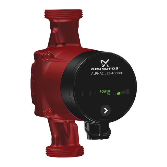
2. General description The GRUNDFOS ALPHA2 L circulator pump is designed for the circulation of water in heating systems. The pump is suitable for the following systems: • underfloor heating systems • one-pipe systems • two-pipe systems. The pump incorporates a permanent-magnet motor and differential-pressure control enabling continuous adjustment of the pump performance to the actual system requirements. -
Page 5: Identification
3. Identification 3.1 Nameplate ALPHA2L 25-40 180 ALPHA2 L 25-40 180 ALPHA2 25-40 180 POWER AUTO ADAPT P1(W) Prod. No. 95047562 Serial No. 00000001 Min. 0.05 KM07183 PC 0833 TF110 Max. 0.19 IP 42 230V ~ 50Hz 0.23 - Part 2 MADE IN DENMARK Fig. -
Page 6: Applications
4. Applications 4.1 System types Fig. 3 Pumped liquids and operating conditions GRUNDFOS ALPHA2 L is suitable for • systems with constant or variable flows where it is desirable to optimise the setting of the pump duty point. • systems with variable flow-pipe temperature. -
Page 7: Mechanical Installation
Mounting the GRUNDFOS ALPHA2 L Arrows on the pump housing indicate the liquid flow direction through the pump. See section 13.2 Installation dimensions, GRUNDFOS ALPHA2 L XX-40, XX-50, XX-60. • Fit the two gaskets supplied when the pump is mounted in the pipe. -
Page 8: Control Box Positions
5.2 Control box positions Fig. 5 Control box positions Warning The pumped liquid may be scalding hot and under high pressure. Drain the system or close the isolating valves on either side of the pump before the screws are removed. Fill the system with the liquid to be pumped or Caution open the isolating valves when the position of the... -
Page 9: Insulation Of Pump Housing
5.4 Insulation of pump housing Fig. 6 Insulation of pump housing Limit the heat loss from the pump housing and Note pipework. The heat loss from the pump and pipework can be reduced by insulating the pump housing and the pipe. See fig. 6. As an alternative, polystyrene insulating shells can be fitted to the pump. -
Page 10: Electrical Installation
6. Electrical installation Fig. 7 Electrical connection Carry out the electrical connection and protection according to local regulations. Warning The pump must be connected to earth The pump must be connected to an external mains switch with a minimum contact gap of 3 mm in all poles. -
Page 11: Control Panel
The pump setting is indicated by seven different light fields. See fig. 9. POWER ALPHA2 L 25-40 180 POWER III II I Fig. 9 Seven light fields Fig. 8 GRUNDFOS ALPHA2 L control panel The control panel comprises: Number of button Light field Description Pos. Description presses "POWER ON"... -
Page 12: Setting The Pump Pump Setting For System Type
8. Setting the pump 8.1 Pump setting for system type POWER POWER POWER ( OK ) POWER POWER POWER OWER ( OK ) POWER POWER POWER ( OK ) POWER POWER POWER ER ( OK ) Fig. 10 Selection of pump setting for system type Factory setting = highest proportional-pressure curve (PP2). -
Page 13: Systems With Bypass Valve Between Flow And Return Pipes
9. Systems with bypass valve between flow and return pipes 9.1 Purpose of bypass valve BYPASS min. POWER (OK) POWER (OK) POWER (OK) POWER POWER POWER ER (OK) Fig. 11 Systems with bypass valve Bypass valve The purpose of the bypass valve is to ensure that the heat from the boiler can be distributed when all valves in the underfloor- heating circuits and/or thermostatic radiator valves are closed. -
Page 14: Startup
10. Startup 10.3 Venting of heating systems 10.1 Before start-up Do not start the pump until the system has been filled with liquid and vented. The required minimum inlet pressure must be available at the pump inlet. See sections 4. Applications and 13. -
Page 15: Pump Settings And Pump Performance
11. Pump settings and pump performance 11.1 Relation between pump setting and pump performance Figure 14 shows the relation between pump setting and pump performance by means of curves. See also section 14. Performance curves. POWER AUTO Fig. 14 Pump setting in relation to pump performance Setting Pump curve Function... -
Page 16: Fault Finding
12. Fault finding Warning Before starting work on the pump, switch off the power supply. Make sure that the power supply cannot be accidentally switched on. Fault Control panel Cause Remedy 1. The pump does not a) A fuse in the installation is blown. Replace the fuse. -
Page 17: Technical Data And Installation Dimensions
13. Technical data and installation dimensions 13.1 Technical data Supply voltage 1 x 230 V - 10 %/+ 10 %, 50/60 Hz, PE. Motor protection The pump requires no external motor protection. Enclosure class IP42. Insulation class Relative air humidity Maximum 95 %. -
Page 18: Installation Dimensions, Grundfos Alpha2 L
13.2 Installation dimensions, GRUNDFOS ALPHA2 L XX-40, XX-50, XX-60 Dimensional sketches and table of dimensions Fig. 15 Dimensional sketches, ALPHA2 L XX-40, XX-50, XX-60 Dimensions Pump type ALPHA2 L 25-40 180 1 1/2 ALPHA2 L 32-40 180 ALPHA2 L 15-50 130*... -
Page 19: Performance Curves
14. Performance curves 14.1 Guide to performance curves Each pump setting has its own performance curve (Q/H curve). A power curve (P1 curve) belongs to each Q/H curve. The power curve shows the pump power consumption (P1) in Watt at a given Q/H curve. -
Page 20: Performance Curves, Alpha2 L
14.3 Performance curves, ALPHA2 L XX-40 [kPa] Q [m³/h] Q [l/s] Q [m³/h] Fig. 17 ALPHA2 L XX-40... -
Page 21: Performance Curves, Alpha2 L Xx-50
14.4 Performance curves, ALPHA2 L XX-50 [kPa] Q [m³/h] Q [l/s] Q [m³/h] Fig. 18 ALPHA2 L XX-50... -
Page 22: Performance Curves, Alpha2 L
14.5 Performance curves, ALPHA2 L XX-60 [kPa] Q [m³/h] Q [l/s] Q [m³/h] Fig. 19 ALPHA2 L XX-60... -
Page 23: Accessories
This product or parts of it must be disposed of in an environmentally sound way: 1. Use the public or private waste collection service. 2. If this is not possible, contact the nearest Grundfos company or service workshop. Subject to alterations. - Page 25 Turkey 20th km. Athinon-Markopoulou Av. New Zealand Тел.: +7 (375 17) 286 39 72, 286 39 73 GRUNDFOS POMPA San. ve Tic. Ltd. Sti. P.O. Box 71 Факс: +7 (375 17) 286 39 71 GRUNDFOS Pumps NZ Ltd. Gebze Organize Sanayi Bölgesi GR-19002 Peania E-mail: minsk@grundfos.com...
- Page 26 95047490 0813 ECM: 1120157 www.grundfos.com...
Need help?
Do you have a question about the alpha2 l and is the answer not in the manual?
Questions and answers