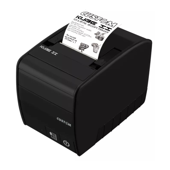
Custom Audio Electronics KUBE II Scanner User Manual
Veriprint
Hide thumbs
Also See for KUBE II Scanner:
- User manual (80 pages) ,
- Short manual (28 pages) ,
- Setup manual (25 pages)
Table of Contents
Advertisement
Quick Links
Download this manual
See also:
Setup Manual
Advertisement
Table of Contents

Related Manuals for Custom Audio Electronics KUBE II Scanner


Summary of Contents for Custom Audio Electronics KUBE II Scanner
- Page 1 USER MANUAL KUBE II Scanner VeriPrint ® CUSTOM S.p.A.
- Page 3 CUSTOM S.p.A. THE CE MARK AFFIXED TO GENERAL SAFETY INFORMATION Your attention is drawn to the following THE PRODUCT CERTIFY Via Berettine 2/B actions that could compromise the char- THAT THE PRODUCT SAT- 43010 Fontevivo (PARMA) - Italy acteristics of the product: ISFIES THE BASIC SAFETY Tel.
- Page 5 MANUAL For details on the commands, refer to the manual with code 77200000000400...
-
Page 7: Table Of Contents
TABLE OF CONTENTS 1 INTRODUCTION ............. . 9 1.1 Document structure . - Page 8 6 MAINTENANCE ............. . 43 6.1 Autocutter paper jam .
-
Page 9: Introduction
1 INTRODUCTION 1.1 Document structure This document includes the following chapters: 1 INTRODUCTION information about this document 2 DRIPTION general dription of device 3 INSTALLATION information required for a correct installation of the device 4 OPERATION information required to make the device operative 5 ... -
Page 11: Description
2 DESCRIPTION 2.1 Box content Remove the device from its carton being careful not to damage the packing material so that it may be re-used if the device is to be transported in the future. Make sure that all the components illustrated below are present and that there are no signs of damage. If there are, contact Customer Service. -
Page 12: Device Components
2.2 Device components External view 1. Paper compartment 2. Paper out (Printer) 3. Stacker 4. Opening lever (Printer) 5. Paper in (Scanner) 6. Opening key (Scanner) 7. Status led 8. FEED key 9. ON/OFF key 10. Paper out (Scanner) 11. USB potr 12. - Page 13 Internal view 1. Sensor for paper detection in the printer unit 2. Sensor for cover open in the printer unit 3. VeriPrint® system over the printhead for the image capturing 4. Sensor for scanner unit open 5. Sensor for paper detection in the scanner unit 6.
-
Page 14: Product Label
2.3 Product label PC = Product code (14 digits) SN = Serial number HW = Hardware release XXXXXXXXXXXXXX 0000000000000000000... -
Page 15: Key Functions: Power Up
2.4 Key functions: power up POWER UP ON/OFF ON/OFF Hold Fast Hold down push down printing printing SETUP report FONT TEST ON/OFF ON/OFF ON/OFF Fast Fast Fast push push push enter the SETUP MODE print the SETUP report enter the SETUP MODE for the printer parameters with Ethernet parameters for the printer clock... -
Page 16: Key Functions: Standby
2.5 Key functions: standby STANDBY ON/OFF ON/OFF Fast Fast push push Advance the paper printing (preset length) demo ticket... -
Page 17: Status Led Lashes
2.6 Status led lashes The Status led indicates hardware status of device. Given in the table below are the various led signals and the corre- sponding device status. STATUS LED DRIPTION PRINTER OFF GREEN PRINTER ON: NO ERROR RECEIVE DATA RECEPTION ERRORS (PARITY, FRAME ERROR, OVERRUN ERROR) GREEN... -
Page 19: Installation
3 INSTALLATION 3.1 Connections The following igure shows the possible connections for the device. ATTENTION: In some using conditions, we recommend the installation of a ferrite core on the power supply cable. RS232 VIn 24Vdc Power ETHERNET Supply cable ETHERNET (included) standard CrossOver cable standard (pin-to-pin) cable Network Cash drawer Power supply Barcode reader Barcode reader... -
Page 20: Pinout
3.2 Pinout POWER SUPPLY Tripolar female connector 1 +24 Vdc 2 GND 3 GND 4 Frame GND ATTENTION: Respect power supply polarity. NOTE: Power supply cable The following igure shows the connector pinout of the power supply cable for the device: Tripolar male connector n.c. +24 V Power supply cable USB INTERFACE Female USB type B connector 1 USB0-VBUS (in) 2 D0 -... -
Page 21: Ethernet Interface
ETHERNET INTERFACE Female RJ45 connector 1 RX+ 2 RX- 3 TX+ 4 n.c 5 n.c 6 TX- 7 n.c 8 n.c NOTES: The functionality of two led are speciied in the following table: FUNCTION The led light (yellow color) on when a connection is active and lashes when occurs a data recep- LED-LNK tion or transmission LED-LAN The led light (green color) on when occurs a 100Mbit connection and off when occurs a 10Mbit connection The printer automatically recognizes the type of connection (cross or pin-to-pin). -
Page 22: Rs232 Serial Interface
RS232 SERIAL INTERFACE RJ45 female connector 1 RTS When “1”, printer is ready to receive data 2 n.c. 3 DTR When “1”, printer is fed 4 GND 5 n.c. 6 RX During reception, takes the values “0” and “1” depending on data. 7 TX During transmission, takes the values “0”... -
Page 23: Drawer Connector
PIN 4 PIN 2 DRAWER 1 KUBE II SCANNER VERIPRINT > CASH DRAWER (optional) connection Use an optional adapter cable RJ12-Jack to connect the device to a cash drawer. Refer to the picture below for the connector pin signals +24Vdc... -
Page 24: Driver And Sdk
3.3 Driver and SDK The drivers are available for the following operating system: OPERATING DESCRIPTION INSTALLATION PROCEDURE SYSTEM Driver for Windows XP Driver for Windows VISTA (32/64bit) From the START menu, press Run and type-in the path where the SW Windows Driver for Windows 7 (32/64bit) was saved on your PC, then click OK. -
Page 25: Operation
4 OPERATION 4.1 Opening the device Printer cover Scanner cover Press the button on the front side and Lift the opening levers and push up the cover. open the printer cover. The indicator shows the state “Cover Open” Lift the cover. -
Page 26: Inserting The Card
4.2 Inserting the card Remove the carter on the printer side using a screwdriver. Contacts facing down Insert the card in the direction shown. -
Page 27: Switch The Device On/Off
4.3 Switch the device ON/OFF IN DC 24V Power supply cable (supplied) VIn 24Vdc Connect the power adapter (supplied) to the device and the mains outlet. Use the type of electrical power supply indicated on the label. ON/OFF Switch device On pressing key ON/OFF, the indicator light is switched on and the device is ready. Switch device Off pressing key ON/OFF for at least 3 seconds. -
Page 28: Loading The Paper Roll
4.4 Loading the paper roll To change the paper proceed as follows. At every change of paper, check inside the device to locate and remove any scraps of paper. Open the device cover. Close the device cover and wait until the paper is loaded and automatically cut off. -
Page 29: Ticket Reading
4.5 Ticket reading The reading of the ticket is handled by command (refer to the manual with code 77200000000400). To read the ticket proceed as follows. TEXT TEXT TEXT TEXT TEXT TEXT TEXT TEXT TEXT TEXT TEXT TEXT TEXT TEXT TEXT TEXT Wait the ticket reading. -
Page 30: Ticket Branding
4.6 Ticket branding The branding of the ticket is handled by command (refer to the manual with code 77200000000400). To brand the ticket proceed as follows. TEXT TEXT TEXT TEXT TEXT TEXT TEXT TEXT TEXT TEXT TEXT TEXT TEXT TEXT TEXT TEXT Wait for the ticket branding. -
Page 31: Veriprint
4.7 VeriPrint system ® VeriPrint® is a system designed by CUSTOM S.p.A. thanks to which the functions of an image scanner and those of a thermal printing head can be integrated in a single component to be included in systems and terminals for POS, betting/ lottery and ticketing application automation. Solutions and beneits with VeriPrint®. -
Page 32: Veriprint ® System
Managing the contents The VeriPrint ® printer is equipped with 3 storage units. When the printer is connected with the PC (using an USB cable) this one detects the storage units as 3 removable disks: Is a lash type internal memory containing the conigurations iles for the printer (setup.ini), Ver- FLASH DRV DISK ®... -
Page 33: Configuration
5 CONFIGURATION 5.1 Coniguration mode To enter the coniguration mode and print a SETUP report with the operating parameters of the device, proceed as follows. KUBEII SCANNER SCODE <code> 1.00 DCODE <code> 1.00 FCODE <code> 1.00 UCODE <code> 1.00 DCODE <code> 1.00 PRINTER SETTINGS PRINTER TYPE .........KUBE SCAN 84MM PRINTING HEAD TYPE ......SHEC T80 FEED Press the FEED key. The device prints the report with parameters for printer settings. -
Page 34: Setup Report
5.2 Setup report The following igures show the setup reports of the device. The shown values for parameters are sample values; for the list and the dription of device and Ethernet parameters see the following paragraphs. KUBEII SCANNER DEVICE NAME and SCODE <code> rel 1.00 BCODE <code> rel 1.00 FIRMWARE MODULES FCODE <code> rel 1.00 RELEASE UCODE <code> rel 1.00 DCODE <code>... -
Page 35: Device Status
[ LF ] enter Printer setup KEYS FUNCTIONS [ ON/OFF ] enter Ethernet Setup [ LF + ON/OFF] skip Setup Disabled DHCP Client ....... : Disabled FTP Server ......... : 192.168. 0. IP Address ........: ETHERNET PARAMETERS 255.255.240. 0 Subnet Mask ...... -
Page 36: Printer Parameters
5.4 Printer parameters This device allows the coniguration of the parameters listed in the following table. The parameters marked with the symbol are the default values. Settings remain active even after the device has been turned off and they are stored in non-volatile memory. RS232 BAUD RATE Communication speed of the serial interface: 115200 9600 57600... - Page 37 USB MASS STORAGE Sharing mode from Mass Storage: Disabled = sharing mode disabled Enabled = sharing mode enabled Numerical address code for the univocal identiication of the USB device (in case of more USB ADDRESS NUMBER than a USB device connected with the same PC): Sharing mode of the detected image (connect a PC via USB): USB INTERFACE 2 Disabled =...
- Page 38 TOTAL CUT Sets the behavior of the cutter when the total cut command 0x1B 0x69 ( i) is sent: Disabled = The total cut command 0x1B 0x69 ( i) will be ignored and the device executes a partial cut Enabled = The total cut command 0x1B 0x69 ( i) will be executed.
-
Page 39: Ethernet Parameters
5.5 Ethernet parameters This device allows the coniguration of the parameters listed in the following table. The parameters marked with the symbol are the default values. Settings remain active even after the device has been turned off. Setting of the DHCP protocol: DHCP CLIENT Disabled = protocol disabled Enabled = protocol enabled Setting of the FTP server: FTP SERVER Disabled... -
Page 40: Hexadecimal Dump
5.6 Hexadecimal dump This function is used for the diagnosis of the characters received from the communications port. Characters are printed as hexadecimal code and the corresponding ASCII code (see below). Each line is preceded by a counter in hexadecimal that indicates the number of bytes received. -
Page 41: Clock Adjustment
5.7 Clock adjustment To adjust the clock, proceed as follows. 1 2 3 4 5 6 7 8 9 Enter setup CLOCK SETUP [LF] to modify date/time [ON/OFF] to next field Enter the setup mode following the instructions in par. 5.1. 00/00/00 00:00:00 20/00/00... -
Page 42: Scanner Unit And Veriprint
5.8 Scanner unit and VeriPrint parameters ® ® To set the operating parameters for the scanner unit and the VeriPrint system, see Par. 11.10 and 11.11. -
Page 43: Maintenance
6 MAINTENANCE 6.1 Autocutter paper jam FEED FEED Press the FEED key. Press the FEED key to try to unlock the cutter. If the cutter did not unlock press slightly the left side of the cutter cover, so that it opens. If the problem persists, please contact the customer service. -
Page 44: Planning Of Cleaning Operations
6.2 Planning of cleaning operations The regular cleaning of the device keeps the print quality and extends its life. The following table shows the recommended planning for the cleaning operations. EVERY PAPER CHANGE Printhead and scanner ‘VeriPrint’ Use isopropyl alcohol Rollers Use isopropyl alcohol EVERY 5 PAPER CHANGES... -
Page 45: Cleaning
6.3 Cleaning For periodic cleaning of the device, see the instructions below Sensors Disconnect the power supply cable and open the device cover (see par. 4.1) Clean the device sensors by using compressed air. ATTENTION: Do not use alcohol, solvents, or hard brushes. Do not let water or other liquids get inside the machine. - Page 46 Paper path Printhead and scanner ‘VeriPrint’ Disconnect the power supply cable and Disconnect the power supply cable and open the device cover (see par. 4.1) open the device cover (see par. 4.1) ISOPROPYL ALCOHOL r i P r i n t P r i ®...
- Page 47 Printhead for branding (scanner unit) Printing roller Disconnect the power supply cable and Disconnect the power supply cable and open the scanner cover (see par. 4.1) open the device cover (see par. 4.1) ISOPROPYL ALCOHOL ISOPROPYL ALCOHOL Clean the printing head by using Disconnect the power supply cable and a non-abrasive cloth moistened with isopropyl.
- Page 48 Cutter Disconnect the power supply cable and open the device cover (see par. 4.1) Press slightly the left side of the cutter cover, so that it opens. Clean the cutter compartment from the inside using compressed air. ATTENTION: Do not use alcohol, solvents, or hard brushes. Do not let water or other liquids get inside the machine.
- Page 49 Case Disconnect the power supply cable Reassemble the cover removed previously. To clean the device, use compressed air or a soft cloth. ATTENTION: Do not use alcohol, solvents, or hard brushes. Do not let water or other liquids get inside the machine. Alcohol, solvent...
-
Page 50: Upgrade Irmware
6.4 Upgrade irmware 9. Select the serial communication port (ex. COM1): WARNING: During communication between PC/device for the irmware update it is strictly forbidden to discon- nect the communication cable or to remove the power supply of the devices not to endanger the proper func- tioning of the device. NOTES: The ... - Page 51 UPDATE VIA USB INTERFACE Custom KUBEIISCANNER ATTENTION: Only during the irmware update, the connection be- tween PC and device must be direct, without the use of wireless HUB. Only during the irmware update, do not connect or disconnect other USB devices. Custom KUBEIISCANNER NOTE: For communication via USB you must install on PC the device driver available in the download area of...
-
Page 53: Specification
7 SPECIFICATION 7.1 Hardware speciications GENERALS Paper presence, head temperature, Sensors cover open, near paper end MTBF 78 340 hours Emulations CUSTOM/POS Windows XP VISTA (32/64bit) Windows 7 (32/64bit) Printing driver Windows 8 (32/64bit) Windows 8.1 (32/64bit) Linux INTERFACES USB Port 480 Mbit/sec (USB 2.0 high speed) RS232 serial port from 1200 to 115200 bps... - Page 54 Head life 100 Km / 100M pulses Printing width 72, 74, 76, 78, 80, 82mm Printing mode Normal, 90°, 180°, 270° Height/Width from 1 to 8, Printing format bold, reverse, underlined, italic PC437, PC850, PC860, PC863, PC865, PC858 (euro), Character fonts 2 TrueType fonts UPCA, UPCE, EAN13, EAN8, CODE39, ITF, CODABAR, CODE93,...
- Page 55 ® VERIPRINT SYSTEM Scanning width 84mm 400, 200 dpi (Vertical) Scanning resolution 600, 300 dpi (Horizontal) Files format BMP (256, 16, 2 gray tones) 400, 300, 200 dpi (Vertical) Saving resolution 600, 300, 200 dpi (Horizontal) SCANNER UNIT Scanning speed 250mm/sec Scanning area 82mm (W) x 350mm (L) max...
- Page 56 Relative humidity from 10% Rh to 85% Rh Storage temperature from -20 °C to +70 °C Storage relative humidity from 10% Rh to 90% Rh NOTES: (1) : Electronic board. (2) : Respecting the regular schedule of cleaning for the device components. (3) : “Veramono.ttf” and “Vera.ttf” are installed on device lash disk. It is possible to install additional TrueType fonts ...
-
Page 57: Character Speciications
7.2 Character speciications Character set Character density 11 cpi 15 cpi 20 cpi Number of columns Character / sec 2250 2895 4050 Lines / sec Characters (L x H mm)-Normal 2,25x3 1,75 x 3 1,25 x 3 NOTE: Theoretical values. -
Page 58: Device Dimensions
7.3 Device dimensions 357 mm (with cover closed) Length 445 mm (with cover open) 216 mm (with cover closed) Height 345 mm (with cover open) Width 140 mm Weight 2535 g NOTE: Dimensions referred to devices without paper roll. All the dimensions shown in following igures are in millimetres. -
Page 59: Power Supply Dimensions Cod. 963Ge020000003
7.4 Power supply dimensions cod. 963GE020000003 Length 127 mm Height 35,5 mm Width 56 mm All the dimensions shown in following igures are in millimetres. AC INLET +24V DC OUTPUT WIRE... -
Page 60: Character Sets In Custom/Pos Emulation
7.5 Character sets in CUSTOM/POS emulation The printer has 3 fonts of varying width (11, 15 and 20 cpi) which may be accessed through programming or control characters. Each of these fonts offers the following code tables: PC437, PC850, PC860, PC863, PC865, PC858. PC437 CODE TABLE (Usa, Standard Europe) “... - Page 61 PC850 CODE TABLE (Multilingual) “ & ‘ Char 0020 0021 0022 0023 0024 0025 0026 0027 0028 0029 002A 002B 002C 002D 002E 002F < > Char 0030 0031 0032 0033 0034 0035 0036 0037 0038 0039 003A 003B 003C 003D 003E 003F...
- Page 62 PC860 CODE TABLE (Portuguese) “ & ‘ Char 0020 0021 0022 0023 0024 0025 0026 0027 0028 0029 002A 002B 002C 002D 002E 002F < > Char 0030 0031 0032 0033 0034 0035 0036 0037 0038 0039 003A 003B 003C 003D 003E 003F...
- Page 63 PC863 CODE TABLE (Canadian, French) “ & ‘ Char 0020 0021 0022 0023 0024 0025 0026 0027 0028 0029 002A 002B 002C 002D 002E 002F < > Char 0030 0031 0032 0033 0034 0035 0036 0037 0038 0039 003A 003B 003C 003D 003E...
- Page 64 PC865 CODE TABLE (Nordic) “ & ‘ Char 0020 0021 0022 0023 0024 0025 0026 0027 0028 0029 002A 002B 002C 002D 002E 002F < > Char 0030 0031 0032 0033 0034 0035 0036 0037 0038 0039 003A 003B 003C 003D 003E 003F...
- Page 65 PC858 CODE TABLE (Euro symbol) “ & ‘ Char 0020 0021 0022 0023 0024 0025 0026 0027 0028 0029 002A 002B 002C 002D 002E 002F < > Char 0030 0031 0032 0033 0034 0035 0036 0037 0038 0039 003A 003B 003C 003D 003E...
- Page 66 In CUSTOM/POS emulation, it is possible to use TrueType fonts. To be used, a TrueType font must be monospace type (every character of the font must have the same dimension). The check is made by the device when the font is selected. TrueType fonts will be automatically scaled by the device in order to obtain the same available width for the embedded fonts (11, 15 and 20 cpi).
-
Page 67: Consumables
8 CONSUMABLES The following table shows the list of available consumables for device: DRIPTION CODE 67300000000410 THERMAL PAPER ROLL weight = 78g/m width = 82.5mm Ø external = 150mm Ø core = 40mm... -
Page 69: Accessories
9 ACCESSORIES The following table shows the list of available accessories for device: DRIPTION CODE 963GE020000003 POWER SUPPLY (for technical speciications, see the paragraph 7.1) 976BG010000003 RIGHT AND LEFT SIDES KUBE-F color: black (see the paragraph 9.1) -
Page 70: Sides Replacement
9.1 Sides replacement To replace the printer side (right or left), proceed as follows: Remove the carter on the printer side Remove the printer side. using a screwdriver. Unscrew the fixing screw Assemble the new side performing the previous for the printer side. operations in reverse order. -
Page 71: Technical Service
10 TECHNICAL SERVICE In case of failure, contact the Technical Service by sending an e-mail to support@custom.it detailing: 1. Product code 2. Serial number 3. Hardware release 4. Firmware release To get the necessary data, proceed as follows: XXXXXXXXXXXXXX 0000000000000000000 support@custom.it support@custom.it Write down the data printed... -
Page 73: Advanced Functions
11 ADVANCED FUNCTIONS 11.1 File sharing The devices can be connected to a PC through two types of connections (see par.3.3): 1. with USB cable 2. with Ethernet cable. According to the connection made, it is possible to manage drivers, fonts and logos of the device and conigure the operat- ing parameters in three different ways: 1. by iles sharing from Mass Storage, in case of USB connection 2. -
Page 74: Embedded Web Server
11.2 Embedded Web Server Device is equipped with an Embedded Web Server that allows to execute some operations on device, through a clear web interface, including: • monitoring the device status; • setting operating parameters; • coniguring network settings; • managing the logos; • coniguring the email service to make diagnostics and maintenance operations easier; • download printing drivers. Before entering in the Embedded Web Server, check that: • ... -
Page 75: Embedded Web Server: Access
11.3 Embedded Web Server: access To enter the Embedded Web Server, type the IP address assigned to the device into Web browser. To know the IP address of the device, print the Set-up report of the device (see chapter 5) or use “Locator”. For example, if IP address of the device is 192.168.10.37, type in the Web browser: http://192.168.10.37 On the screen will appear the internal default page that corresponds to the section “Device Info”... - Page 76 To enter some sections and some coniguration services, it is required the identiication of the user and password. To make registration and to obtain the access to the restricted areas, when it is required insert the user name and the password as indicated in the following table: Custom User Name AlwaysOn Password NOTE: Respect capital and small letters as indicated in table.
-
Page 77: Embedded Web Server: Functions
11.4 Embedded Web Server: functions The “Printer Settings” section is a restricted one. To enter the section, it is required the identiication of the user and pass- word. With the tools of this section, it is possible to set up the same parameters of the device that are conigurable in the device’s Set-up mode (see chapter 5). The following igure shows the page for the “EMAIL SETUP” tool. It is divided into 4 areas: SECTIONS: Are the same as dribed on the main page CURRENT PAGE Reports section currently displayed. TOOLS Lists the tools available within the chosen section. Displays the ields available to conigure the automatically delivery of service email in EMAIL SETUP order to inform the user when a change occurs to operating status of the device. -
Page 78: Advanced Function
With the tools in the “Printer Support” section, it is possible to download drivers, manage logos and test some device func- tion for demonstrative and service purpose, The following igure shows the page for the “ADVANCED FUNCTIONS” tool. It is divided into 4 areas: SECTIONS: Are the same as dribed on the main page CURRENT PAGE Reports section currently displayed. -
Page 79: Locator
11.5 Locator With the device it is possible to use an external software to perform a search for devices connected to the network with Ethernet cable, even without knowing the IP addresses of individual device The following igure shows the software interface: DEVICES: Displays the list of the connected devices. “START...”... -
Page 80: Drivers Installation
11.6 Drivers installation Embedded Web Server To install a new driver update for the device, enter the “DRIVER” page of the “PRINTER SUPPORT” section of the embed- ded Web Server (see the following igure). DEVICE INFO │ PRINTER SETTINGS │ PRINTER SUPPORT Web Site < Device name > R > R I N <... -
Page 81: Logos Management
11.7 Logos management It is possible to store new logos in addition to default logos stored on Flash Disk. The device automatically provides to convert BMP image to the error-diffusion format in black and white. Logos may be stored both on Flash Disk and on the Memory Card. The use of the Memory Card allows to handle more logos (however, the max number of manageable logos is limited by the RAM memory reserved for logos management). - Page 82 Mass Storage / FTP Server It is possible to add the new logo directly into the folder “PICTURES” on the Flash Drive of the device. You can enter the Flash Drive by iles sharing from Mass Storage or by iles sharing from FTP Server connection (see par. 11.1). In both cases, the relative parameter should be enabled during the coniguration process (see chapter 5). After adding the logo, open the coniguration ile “PictList.ini” and add a new line with a number associated to the logo (to be used with device’s commands), a letter for the memory unit and the logo ile name, as indicated in the instructions written inside the “PictList.ini” ile. To delete a logos stored in the device, proceed as follows: 1.
-
Page 83: Fonts Management
11.8 Fonts management It is possible to store new font in addition to default fonts stored on Flash Disk. Fonts may be stored both on Flash Disk and on the Memory Card. The use of the Memory Card allows to handle more fonts (however, the max number of manageable fonts is limited by the RAM memory reserved for fonts management). - Page 84 Mass Storage / FTP Server It is possible to add the new font directly into the folder “FONTS” on the Flash Drive of the device. You can enter the Flash Drive by iles sharing from Mass Storage or by iles sharing from FTP Server connection (see par. 11.1). In both cases, the relative parameter should be enabled during the coniguration process (see chapter 5). NOTE: To know the IP address of the device, print the Set-up report of the device (see chapter 5) or use “Locator”. Type in the address bar “ftp://”...
-
Page 85: Printer Setup
11.9 Printer setup Embedded Web Server Device permits the coniguration of default parameters for device and network setup by entering the “PRINTER SETUP” page and the “NETWORK SETUP” page of the “PRINTER SETTINGS” section of the embedded Web Server (see the following igure). DEVICE INFO │ PRINTER SETTINGS │ PRINTER SUPPORT Web Site < Device name > R > R I N < P PRINTER SETTINGS <... - Page 86 The “Setup.ini” ile is a coniguration ile that contains all the conigurable parameters listed in text format and divided into some sections (indicated in square brackets). The available values for every parameter, are listed after the parameter name. The value marked with the symbol ‘ * ’ is the default one. To modify device’s parameters, change the numeric value after the name of parameters. To set the parameter to the default value, change the numeric value with the symbol D.
- Page 87 RS232 Data Length 0*, 1 0 = 8 bits/chr 1 = 7 bits/chr RS232 Parity 0*, 1, 2 0 = None 2 = Odd 1 = Even RS232 Handshaking 0*, 1 0 = Xon/Xoff 1 = Hardware Busy Condition 0*, 1 0 = RxFull 1 = OffLine/RxFull USB Address Number...
-
Page 88: Veriprint
11.10 VeriPrint setup ® Mass Storage / FTP Server It is possible to conigure the default parameters for VeriPrint system by editing the “Scanner.cfg” ile on the device Flash Drive. You can enter the Flash Drive by iles sharing from Mass Storage or by iles sharing from FTP Server connection (see par.11.1). In both cases, the relative parameter should be enabled during the coniguration process (see chapter 5). After editing device’s parameter, simply save the “Scanner.cfg” ile to make the modiies activated. The “Scanner.cfg” ile is a coniguration ile that contains all the conigurable parameters listed in text format and divided into some sections (indicated in square brackets). The available values for every parameter, are listed after the parameter name. The value marked with the symbol ‘ * ’ is the default one. - Page 89 JOURFILENAME ‘image’*, 0, 1, 2 bmp salvato nel disco SD/MMC CARD ‘image’ = <name of ile without extension, max 12 chars> 0 = no ile 1 = DDMMYYhhmmss.bmp 2 = YYMMDDhhmmss.bmp JOURFULLMODE 0*, 1, 2 SD/MMC CARD full behaviour: 0 = erase oldest folders 1 = ile not saved 2 = stop print JOURCROP 0, 1* crop of bmp saved in SD/MMC CARD: 0 = no crop 1 = crop...
-
Page 90: Scanner Unit Setup
11.11 Scanner unit setup Mass Storage / FTP Server It is possible to conigure the default parameters for scanner unit by editing the “Scanner_ext.cfg” ile on the device Flash Drive. You can enter the Flash Drive by iles sharing from Mass Storage or by iles sharing from FTP Server connection (see par.11.1). In both cases, the relative parameter should be enabled during the coniguration process (see chapter 5). After editing device’s parameter, simply save the “Scanner_ext.cfg” ile to make the modiies activated. The “Scanner_ext.cfg” ile is a coniguration ile that contains all the conigurable parameters listed in text format and divided into some sections (indicated in square brackets). The available values for every parameter, are listed after the parameter name. The value marked with the symbol ‘ * ’ is the default one. - Page 91 JOURBITPIXEXT 8, 4, 1* colour depth of bmp saved in SD/MMC CARD JOURFILENAMEEXT ‘image’*, 0, 1, 2 bmp name saved in SD/MMC CARD: ‘image’ = <name of ile without extension, max 12 chars> 0 = no ile 1 = DDMMYYhhmmss.bmp 2 = YYMMDDhhmmss.bmp JOURFULLMODE 0*, 1, 2 SD/MMC CARD full behaviour: 0 = erase oldest folders 1 = ile not saved 2 = stop print JOURCROP...
- Page 92 CUSTOM S.p.A. World Headquarters Via Berettine, 2/B - 43010 Fontevivo, Parma ITALY Tel. +39 0521 680111 - Fax +39 0521 610701 info@custom.biz - www.custom.biz All rights reserved www.custom.biz...
Need help?
Do you have a question about the KUBE II Scanner and is the answer not in the manual?
Questions and answers