Table of Contents
Advertisement
Visit our website at
www.MillerWelds.com
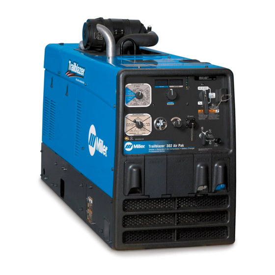
Trailblazer 302 Air Pak
OM-229 930K
2011−11
Processes
MIG (GMAW) Welding
Flux Cored (FCAW)
Stick (SMAW) Welding
TIG (GTAW) Welding
Air Plasma Cutting and Gouging
with Spectrum
Air Carbon Arc (CAC-A) Cutting
and Gouging
Battery Charging
Description
Engine Driven Welding Generator And
Air Compressor
R
File: Engine Drive
R
Unit
™
Advertisement
Table of Contents
Troubleshooting

Related Manuals for Miller TRAILBLAZER 302 AIR PAK


Summary of Contents for Miller TRAILBLAZER 302 AIR PAK
- Page 1 TIG (GTAW) Welding Air Plasma Cutting and Gouging with Spectrum Unit Air Carbon Arc (CAC-A) Cutting and Gouging Battery Charging Description Engine Driven Welding Generator And Air Compressor Trailblazer 302 Air Pak ™ File: Engine Drive Visit our website at www.MillerWelds.com...
- Page 2 We know you don’t have time to do it any other way. That’s why when Niels Miller first started building arc welders in 1929, he made sure his products offered long-lasting value and superior quality.
-
Page 3: Table Of Contents
TABLE OF CONTENTS SECTION 1 − SAFETY PRECAUTIONS − READ BEFORE USING ....... . 1-1. - Page 4 TABLE OF CONTENTS 6-6. Lift-Arct TIG With Auto-Cratert And Auto-Stopt ........6-7.
-
Page 5: Section 1 − Safety Precautions − Read Before Using
SECTION 1 − SAFETY PRECAUTIONS − READ BEFORE USING rom_2011−04 Protect yourself and others from injury — read, follow, and save these important safety precautions and operating instructions. 1-1. Symbol Usage DANGER! − Indicates a hazardous situation which, if Indicates special instructions. not avoided, will result in death or serious injury. - Page 6 D Do not weld on closed containers such as tanks, drums, or pipes, FUMES AND GASES can be hazardous. unless they are properly prepared according to AWS F4.1 (see Safety Standards). Welding produces fumes and gases. Breathing these D Do not weld where the atmosphere may contain flammable dust, fumes and gases can be hazardous to your health.
-
Page 7: Engine Hazards
1-3. Engine Hazards EXHAUST SPARKS can cause fire. BATTERY EXPLOSION can injure. D Do not let engine exhaust sparks cause fire. D Always wear a face shield, rubber gloves, and protective clothing when working on a battery. D Use approved engine exhaust spark arrestor in required areas —... -
Page 8: Hydraulic Hazards
1-4. Hydraulic Hazards D HYDRAULIC FLUID is FLAMMABLE−−do not work on hydraulics HYDRAULIC EQUIPMENT can injure near sparks or flames; do not smoke near hydraulic fluid. or kill. D Reinstall doors, panels, covers, or guards when servicing is D Incorrect installation or operation of this unit finished and before starting unit. -
Page 9: Additional Symbols For Installation, Operation, And Maintenance
HOT METAL from air arc cutting and MOVING PARTS can injure. gouging can cause fire or explosion. D Keep away from moving parts such as fans, D Do not cut or gouge near flammables. belts and rotors. D Watch for fire; keep extinguisher nearby. D Keep all doors, panels, covers, and guards closed and securely in place. -
Page 10: California Proposition 65 Warnings
WELDING WIRE can injure. H.F. RADIATION can cause interference. D Do not press gun trigger until instructed to do D High-frequency (H.F.) can interfere with radio navigation, safety services, computers, and communications equipment. D Do not point gun toward any part of the body, other people, or any metal when threading D Have only qualified persons familiar with welding wire. -
Page 11: Principal Safety Standards
1-8. Principal Safety Standards Safety in Welding, Cutting, and Allied Processes, ANSI Standard Z49.1, 25 West 43rd Street, New York, NY 10036 (phone: 212-642-4900, web- from Global Engineering Documents (phone: 1-877-413-5184, website: site: www.ansi.org). www.global.ihs.com). Standard for Fire Prevention During Welding, Cutting, and Other Hot Safe Practices for the Preparation of Containers and Piping for Welding Work, NFPA Standard 51B, from National Fire Protection Association, and Cutting, American Welding Society Standard AWS F4.1, from Glob-... -
Page 12: Section 2 − Consignes De Sécurité − Lire Avant Utilisation
SECTION 2 CONSIGNES DE SÉCURITÉ − LIRE AVANT − UTILISATION fre_rom_2011−04 Pour écarter les risques de blessure pour vous−même et pour autrui — lire, appliquer et ranger en lieu sûr ces consignes relatives aux précautions de sécurité et au mode opératoire. 2-1. - Page 13 Il reste une TENSION DC NON NÉGLIGEABLE dans les LES RAYONS DE L’ARC peuvent sources de soudage onduleur UNE FOIS le moteur coupé. provoquer des brûlures dans les yeux et sur la peau. D Couper l’alimentation du poste et décharger les condensateurs d’entrée comme indiqué...
-
Page 14: Dangers Existant En Relation Avec Le Moteur
D Protéger les bouteilles de gaz comprimé d’une chaleur excessive, LE BRUIT peut affecter l’ouïe. des chocs mécaniques, des dommages physiques, du laitier, des flammes ouvertes, des étincelles et des arcs. Le bruit des processus et des équipements peut D Placer les bouteilles debout en les fixant dans un support station- affecter l’ouïe. -
Page 15: Dangers Liés À L'hydraulique
D Mettre des lunettes de sécurité et des gants, placer un torchon sur LES ÉTINCELLES À L’ÉCHAPPEMENT le bouchon du radiateur. peuvent provoquer un incendie. D Dévisser le bouchon légèrement et laisser la vapeur s’échapper avant d’enlever le bouchon. D Empêcher les étincelles d’échappement du moteur de provoquer un incendie. -
Page 16: Dangers Liés À L'air Comprimé
Les PIÈCES MOBILES peuvent causer LES PIÈCES ET LIQUIDES CHAUDS des blessures. peuvent provoquer des brûlures. D S’abstenir de toucher des parties mobiles telles D Ne pas toucher les pièces chaudes à main nue que des ventilateurs, courroies et rotors. ni laisser des liquides chauds entrer en contact avec la peau. -
Page 17: Dangers Supplémentaires En Relation Avec L'installation, Le Fonctionnement Et La Maintenance
D Remettre en place les portes, panneaux, recouvrements ou PRESSION D’AIR RÉSIDUELLE dispositifs de protection à la fin des travaux d’entretien et avant ET DES FLEXIBLES QUI FOUETTENT de mettre le moteur en marche. risquent de provoquer des blessures. D Détendre la pression pneumatique des outils et PIÈCES CHAUDES peuvent... -
Page 18: Proposition Californienne 65 Avertissements
D Demander seulement à des personnes qualifiées familiarisées LES CHARGES ÉLECTROSTATI- avec des équipements électroniques de faire fonctionner l’installa- QUES peuvent endommager les tion. circuits imprimés. D L’utilisateur est tenu de faire corriger rapidement par un électricien qualifié les interférences résultant de l’installation. D Établir la connexion avec la barrette de terre avant de manipuler des cartes ou des pièces. -
Page 19: Principales Normes De Sécurité
2-8. Principales normes de sécurité Safety in Welding, Cutting, and Allied Processes, ANSI Standard Z49.1, 25 West 43rd Street, New York, NY 10036 (phone: 212-642-4900, web- from Global Engineering Documents (phone: 1-877-413-5184, website: site: www.ansi.org). www.global.ihs.com). Standard for Fire Prevention During Welding, Cutting, and Other Hot Safe Practices for the Preparation of Containers and Piping for Welding Work, NFPA Standard 51B, from National Fire Protection Association, and Cutting, American Welding Society Standard AWS F4.1, from Glob-... -
Page 20: Section 3 − Definitions
A complete Parts List is available at www.MillerWelds.com SECTION 3 − DEFINITIONS 3-1. Symbol Definitions Fast Fast/Slow Stop Engine Slow (Idle) (Run, Weld/Power) (Run/Idle) Start Engine Panel/Local Temperature Fuel Check Valve Engine Oil Engine Choke Battery Clearance Read Operator’s Engine Amperes Volts Manual... -
Page 21: Section 4 − Specifications
A complete Parts List is available at www.MillerWelds.com SECTION 4 − SPECIFICATIONS 4-1. Weld, Power, And Engine Specifications Rated Maximum Welding Weld Generator Fuel Welding Open-Circuit Engine Mode Output Range Power Rating Capacity Output Voltage 280 A, 32 V, 100% CC/DC 10 −... -
Page 22: Dimensions, Weights, And Operating Angles
A complete Parts List is available at www.MillerWelds.com 4-5. Dimensions, Weights, and Operating Angles Dimensions 34−1/4 in. (870 mm) Height (To Top Of Air Cleaner) Width 20 in. (508 mm) Do not exceed tilt angles or engine could Depth 59−5/8 in. (1514 mm) be damaged or unit could tip. -
Page 23: Fuel Consumption Curves
A complete Parts List is available at www.MillerWelds.com 4-6. Fuel Consumption Curves A. Welding 2.25 2.00 1.75 1.50 1.25 1.00 0.75 0.50 IDLE 0.25 0.00 DC WELD AMPERES AT 100% DUTY CYCLE Auxiliary Power 2.25 2.00 1.75 1.50 1.25 1.00 0.75 0.50 IDLE... -
Page 24: Generator Power Curve
A complete Parts List is available at www.MillerWelds.com 4-7. Generator Power Curve The AC generator power curve shows the generator power avail- able in amperes at the receptacles. Tools and motors are designed to operate within 10% of 120/240 VAC. 13,000 WATTS AC AMPERES 235 695-A... -
Page 25: Stick And Mig Mode Volt-Ampere Curves
A complete Parts List is available at www.MillerWelds.com 4-9. Stick And MIG Mode Volt-Ampere Curves A. CC/DC Stick Mode The volt-ampere curves show the minimum and maximum voltage and amperage output capabilities of the welding generator. Curves of other settings fall between the curves shown. -
Page 26: Tig Mode Volt-Ampere Curves
A complete Parts List is available at www.MillerWelds.com 4-10. TIG Mode Volt-Ampere Curves The volt-ampere curves show the minimum and maximum voltage and amperage output capabilities of A. CC/AC TIG Mode the welding generator. Curves of other settings fall between the curves shown. -
Page 27: Section 5 − Installation
A complete Parts List is available at www.MillerWelds.com SECTION 5 − INSTALLATION 5-1. Serial Number And Rating Label Location The serial number and rating information for this product is located on the rear panel. Use rating label to determine rated output. For future reference, write serial number in space provided on back cover of this manual. -
Page 28: Grounding Generator To Truck Or Trailer Frame
A complete Parts List is available at www.MillerWelds.com 5-3. Grounding Generator To Truck Or Trailer Frame Always ground generator frame to vehicle frame to pre- vent electric shock and static electricity hazards. Also see AWS Safety & Health Fact Sheet No. 29, Grounding of Portable And Vehicle Mounted Welding Generators. -
Page 29: Engine Prestart Checks
A complete Parts List is available at www.MillerWelds.com 5-4. Engine Prestart Checks Check all fluids daily. Engine must be cold and on a level surface. Unit is shipped with 10W30 engine oil. Follow run-in procedure in en- gine manual. This unit has a low oil pressure shutdown switch. -
Page 30: Compressor Prestart Checks
A complete Parts List is available at www.MillerWelds.com 5-5. Compressor Prestart Checks Primary Oil Fill/ Check Use only Mobil 1 Synthetic ATF oil. Optional Oil Fill/Check Keep oil level threaded area of fill pipe. 236 200 Check all fluids daily. Compressor must be ature shutdown. -
Page 31: Connecting The Battery
A complete Parts List is available at www.MillerWelds.com 5-6. Connecting the Battery Connect negative (−) battery cable last. To connect battery, open top − service door. Tools Needed: 1/2 in. Ref. 229 219-A / Ref. S-0756-D / 804 953-B 5-7. Installing Exhaust Pipe Stop engine and let cool. -
Page 32: Weld Output Terminals
A complete Parts List is available at www.MillerWelds.com 5-8. Weld Output Terminals Stop engine. Do not connect to CC and CV terminals at the same time. Work Weld Output Terminal Stick/TIG (CC) Weld Output Terminal Wire (CV) Weld Output Terminal For MIG welding, connect work cable to Work terminal and wire feeder cable to Wire (CV) terminal. -
Page 33: Selecting Weld Cable Sizes
**Weld cable size (AWG) is based on either a 4 volts or less drop or a current density of at least 300 circular mils per ampere. ( ) = mm for metric use ***For distances longer than those shown in this guide, call a factory applications rep. at 920-735-4505 (Miller) or 1-800-332-3281 (Hobart). Ref. S-0007-J 2011−07 5-11. Remote Receptacle Information... -
Page 34: Connecting To The Air Compressor
(not supplied). Protect hose from rubbing on sheet metal base. Obtain optional 50 ft (15 m) air hose with 1/2 in. NPT swivel fitting (Miller Part No. 300 571). 804 953-A / WM Design OM-229 930 Page 30... -
Page 35: Section 6 − Operating Welding Generator
A complete Parts List is available at www.MillerWelds.com SECTION 6 − OPERATING WELDING GENERATOR 6-1. Engine Controls Ref. 804 857-C / Ref. 245 069-A Engine Control Switch Battery Jump 3600 RPM Engine Choke Control Use switch to start engine, select speed, Use control to change engine air-fuel mix Multiple Loads 3600 RPM... -
Page 36: Voltage/Amperage Control
A complete Parts List is available at www.MillerWelds.com 6-3. Voltage/Amperage Control 1 And 2 Displays Displays show weld process infor- mation (voltage and amperage) and maintenance information (hour meter, oil change countdown, or RPM). Meter Weld Functions: In Wire modes, Voltmeter displays preset weld voltage when not welding. -
Page 37: Process/Contactor Switch
A complete Parts List is available at www.MillerWelds.com 6-4. Process/Contactor Switch Ref. 804 857-C / Ref. 245 069-A Process/Contactor Switch low dig/arc force setting for smooth weld Medium Arc - This setting provides me- performance. A stable weld puddle with dium dig/arc force for open root vertical up Weld output terminals are energized little arc “snap”... -
Page 38: Stick Scratch Start
A complete Parts List is available at www.MillerWelds.com Table 6-1. Process/Contactor Switch Settings Switch Setting Process Output On/Off Control Electrode Hot − Wire MIG (GMAW) Electrode Hot Stick (SMAW) Electrode Hot − Stick Electrode Hot Select Preferred Dig Air Carbon Arc (CAC-A) Cutting And Gouging Electrode Hot −... -
Page 39: Lift-Arct Tig With Auto-Cratert And Auto-Stopt
A complete Parts List is available at www.MillerWelds.com 6-6. Lift-Arct TIG With Auto-Cratert And Auto-Stopt Arc Start With Lift-Arc TIG Lift-Arc is used for the DCEN GTAW process when HF Start method is not permitted. Arc Start With Lift-Arc Select Lift-Arc at Process/Contac- tor switch. -
Page 40: Remote Voltage/Amperage Control
A complete Parts List is available at www.MillerWelds.com 6-7. Remote Voltage/Amperage Control Remote Receptacle RC4 Connect optional remote voltage/ amperage (V/A) control to RC4 (see Section 5-11). Use receptacle to connect remote control or wire feeder. When a remote voltage/amperage control is connected to the Remote receptacle, the Auto Sense Re- mote... -
Page 41: Section 7 − Compressor Operation
A complete Parts List is available at www.MillerWelds.com SECTION 7 − COMPRESSOR OPERATION 7-1. Air Compressor Switch air, install optional air cooler with sep- To reset oil change hours: with engine off, Weld output and generator power are arator (Part No. 300 420), or desiccant place switch in Engine or Compressor Oil reduced when the air compressor is dryer (Part No. -
Page 42: Air Compressor Gauge And Regulator
A complete Parts List is available at www.MillerWelds.com 7-2. Air Compressor Gauge And Regulator Ref. 804 857-C / Ref. 245 069-A / 229 807-B Adjust system pressure with the regulator. pressor will supply 80 psi regardless of The air pressure gauge reads the air Set pressure in the no-flow condition only. -
Page 43: Compressor Blow Down
A complete Parts List is available at www.MillerWelds.com 7-4. Compressor Blow Down Blow Down Valve To prevent foaming or sudden release of pressure, allow 10 minutes after shutdown before opening the compressor oil dip- stick/fill cap or performing other compressor maintenance. To control the release of air mixed in the compressor oil (while running), the compressor goes through a... -
Page 44: Section 8 − Battery Charging
A complete Parts List is available at www.MillerWelds.com SECTION 8 − BATTERY CHARGING 8-1. Battery Charging Guidelines Stop welding generator engine. Have only qualified persons do bat- Keep battery charging cables away Place Air Compressor switch in the tery charging work. from vehicle hood, door, and mov- Off position. -
Page 45: Connecting Installed Battery To Battery Charge Receptacle
A complete Parts List is available at www.MillerWelds.com 8-3. Connecting Installed Battery To Battery Charge Receptacle Battery located in vehicle (Negative post grounded to chassis) See information below regarding vehicles with battery Positive (+) grounded to chassis. − Connect black (Negative) char- ging cable to chassis or engine block (and away from battery). -
Page 46: Setting Battery Charge Controls
A complete Parts List is available at www.MillerWelds.com 8-4. Setting Battery Charge Controls Have only qualified persons charge batteries. DC/Battery/AC Switch Place switch in Jump/Charge posi- tion. Air Compressor Switch Place switch in position matching voltage of battery being charged. NOTICE −... -
Page 47: Section 9 − Operating Auxiliary Equipment
A complete Parts List is available at www.MillerWelds.com SECTION 9 − OPERATING AUXILIARY EQUIPMENT 9-1. Generator Power Receptacles And Supplementary Protectors Ref. 245 069 put from RC2 or RC3 is 2.4 kVA/kW. ceptacles do not work. Place switch in On Use GFCI protection when operat- position to reset. -
Page 48: Wiring Instructions For Optional 240 Volt, Single-Phase Plug (Nema 14-50P)
A complete Parts List is available at www.MillerWelds.com 9-3. Wiring Instructions For Optional 240 Volt, Single-Phase Plug (NEMA 14-50P) The plug can be wired for a 240 V, 2-wire load or a 120/240V, 3-wire load. See circuit diagram. Plug Wired for 120/240 V, 3-Wire Load When wired for 120 V loads, each duplex receptacle shares a load... -
Page 49: Section 10 − Generator/Engine Maintenance
A complete Parts List is available at www.MillerWelds.com SECTION 10 − GENERATOR/ENGINE MAINTENANCE 10-1. Maintenance Label OM-229 930 Page 45... -
Page 50: Routine Generator/Engine Maintenance
A complete Parts List is available at www.MillerWelds.com 10-2. Routine Generator/Engine Maintenance Use information displayed on the Voltmeter/Ammeter displays to assist in scheduling maintenance (see Section 6-3). Engine speed is regulated by an electronic governor. Engine speed adjustments may only be performed by a Factory Authorized Service Agent. Follow the storage procedure in the engine owner’s manual if the unit will not be used for an extended period. -
Page 51: Servicing Air Cleaner
A complete Parts List is available at www.MillerWelds.com 10-3. Servicing Air Cleaner Stop engine. Do not run engine without air cleaner or with dirty element. En- gine damage caused by using a damaged element is not covered by the warranty. The air cleaner primary element can be cleaned but the dirt holding capac- ity of the filter is reduced with each... -
Page 52: Changing Engine Oil, Oil Filter, And Fuel Filter
A complete Parts List is available at www.MillerWelds.com 10-4. Changing Engine Oil, Oil Filter, And Fuel Filter Stop engine and let cool. Oil Drain Valve Oil Filter Change engine oil and filter accord- ing to engine manual. Close valve and valve cap before adding oil and run- ning engine. -
Page 53: Overload Protection
A complete Parts List is available at www.MillerWelds.com 10-5. Overload Protection Stop engine. Open left side door. When a circuit breaker, supple- mentary protector or fuse opens, it usually indicates a more serious problem exists. Contact a Factory Authorized Service Agent. Supplementary Protector CB4 Supplementary Protector CB6 CB4 protects the stator winding... -
Page 54: Servicing Optional Spark Arrestor
A complete Parts List is available at www.MillerWelds.com 10-6. Servicing Optional Spark Arrestor Stop engine and let cool. Spark Arrestor Screen Clean and inspect screen. Replace spark arrestor if screen wires are broken or missing. Tools Needed: 1/4 in. 804 951 / Ref. 803 572−A Notes Work like a Pro! Pros weld and cut... -
Page 55: Section 11 − Air Compressor Maintenance
A complete Parts List is available at www.MillerWelds.com SECTION 11 − AIR COMPRESSOR MAINTENANCE 11-1. Maintenance Stop engine before maintaining. Recycle See compressor Maintenance engine Label for important start-up and fluids. service information. Service compressor more often if used in severe conditions. -
Page 56: Compressor Maintenance Label
A complete Parts List is available at www.MillerWelds.com 11-3. Compressor Maintenance Label OM-229 930 Page 52... -
Page 57: Servicing Compressor Air Cleaner And Air/Oil Separator
A complete Parts List is available at www.MillerWelds.com 11-4. Servicing Compressor Air Cleaner And Air/Oil Separator Stop engine. Wait 10 minutes for compressor blow down cycle to complete be- fore performing maintenance. NOTICE − Do not run air compressor without air cleaner or with dirty element. Compressor damage caused by using a damaged element is not covered by the warranty. -
Page 58: Changing Air Compressor Oil And Filter
A complete Parts List is available at www.MillerWelds.com 11-5. Changing Air Compressor Oil And Filter Tools Needed: 7/8, 15/16 in. 804 950-C / 804 951-C / 804 952-A Drain compressor oil while compressor is still filter. Install new filter and turn clockwise until Stop engine and let cool. -
Page 59: Section 12 − Troubleshooting
A complete Parts List is available at www.MillerWelds.com SECTION 12 − TROUBLESHOOTING 12-1. Front Panel Display Code Information Left Display Right Display Description How/When Code Is Displayed Code is displayed when engine is running, Engine Control switch is in Run 10 −... -
Page 60: Front Panel Display Code Information For Battery Charger
A complete Parts List is available at www.MillerWelds.com 12-2. Front Panel Display Code Information For Battery Charger Right Left Display Description How/When Code Is Displayed Display DC/Battery/AC Switch in Jump/ Code is displayed when Air Compressor switch is not in a battery charge or JUMP CHRG Charge position... -
Page 61: Welding Troubleshooting
A complete Parts List is available at www.MillerWelds.com 12-3. Welding Troubleshooting Trouble Remedy No weld output. Check weld control settings. Check weld connections. Disconnect equipment from generator power receptacles during start-up. Increase front panel and/or remote voltage/amperage control settings (see Sections 6-3 and 6-7). Check and secure connections to Remote receptacle RC4 (see Sections 5-11). -
Page 62: Generator Power Troubleshooting
A complete Parts List is available at www.MillerWelds.com Trouble Remedy Tungsten electrode oxidizing and not Shield weld zone from drafts. remaining bright after conclusion of weld. Increase postflow time. Check and tighten all gas fittings. Properly prepare tungsten. 12-4. Generator Power Troubleshooting Trouble Remedy No power output. -
Page 63: Compressor Troubleshooting
A complete Parts List is available at www.MillerWelds.com Trouble Remedy Battery discharges between uses. Place Engine Control switch in Off position when unit is not running. Clean top of battery with baking soda and water solution; rinse with clear water. Periodically recharge battery (approximately every 3 months). - Page 64 A complete Parts List is available at www.MillerWelds.com Trouble Remedy Air compressor stops after short period Check compressor oil level (see Section 5-5). Automatic shutdown stops compressor if compressor tem- of operation. perature is too high. Circuit breaker CB5 is open. CB5 automatically resets when the compressor cools. If CB5 continues to open, contact Factory Authorized Service Agent.
-
Page 65: Battery Charge/Jump Troubleshooting
A complete Parts List is available at www.MillerWelds.com Trouble Remedy Air compressor overheats (continued) Adjust compressor air pressure (see Section 7-2). Replace compressor oil filter (see Section 11-5). Have Factory Authorized Service Agent check cooling fan. Automatic shutdown stops compressor if compressor temperature is too high. -
Page 66: Section 14 − Electrical Diagrams
SECTION 14 − ELECTRICAL DIAGRAMS Figure 14-1. Circuit Diagram For Welding Generator OM-229 930 Page 62... - Page 67 245 075-B OM-229 930 Page 63...
-
Page 68: Section 15 − Generator Power Guidelines
SECTION 15 − GENERATOR POWER GUIDELINES The views in this section are intended to be representative of all engine-driven welding generators. Your unit may differ from those shown. 15-1. Selecting Equipment Generator Power Receptacles − Neutral Bonded To Frame 3-Prong Plug From Case Grounded Equipment 2-Prong Plug From Double Insulated Equipment... - Page 69 15-3. Grounding When Supplying Building Systems Equipment Grounding Terminal Grounding Cable Use #8 AWG or larger insulated copper wire. GND/PE Ground Device Use ground device as stated in electrical codes. Ground generator to system earth ground if supplying power to a premises (home, shop, farm) wiring system.
- Page 70 15-5. Approximate Power Requirements For Industrial Motors Industrial Motors Rating Starting Watts Running Watts Split Phase 1/8 HP 1/6 HP 1225 1/4 HP 1600 1/3 HP 2100 1/2 HP 3175 Capacitor Start-Induction Run 1/3 HP 2020 1/2 HP 3075 3/4 HP 4500 1400 1 HP...
- Page 71 15-7. Approximate Power Requirements For Contractor Equipment Contractor Rating Starting Watts Running Watts Hand Drill 1/4 in 3/8 in 1/2 in Circular Saw 6-1/2 in 7-1/4 in 8-1/4 in 1400 1400 Table Saw 9 in 4500 1500 10 in 6300 1800 Band Saw 14 in...
- Page 72 15-8. Power Required To Start Motor Single-Phase Induction Motor Starting Requirements Motor Start Code KVA/HP 10.0 11.2 12.5 14.0 Motor Start Code Running Amperage Motor HP Motor Voltage To find starting amperage: Step 1: Find code and use table to find kVA/HP.
- Page 73 15-10. Typical Connections To Supply Standby Power Have only qualified persons perform these connections according to all applicable codes and safety practices. Properly install, ground, and operate this equipment ac- cording to its Owner’s Manu- Fused Welding Utility al and national, state, and lo- Disconnect Electrical Generator...
- Page 74 15-11. Selecting Extension Cord (Use Shortest Cord Possible) Cord Lengths for 120 Volt Loads Use GFCI protection when operating auxiliary equipment. If unit does not have GFCI receptacles, use GFCI-protected exten- sion cord. Maximum Allowable Cord Length in ft (m) for Conductor Size (AWG)* Current (Amperes) Load (Watts)
- Page 75 Effective January 1, 2011 (Equipment with a serial number preface of MB or newer) This limited warranty supersedes all previous Miller warranties and is exclusive with no other Warranty Questions? guarantees or warranties expressed or implied. LIMITED WARRANTY − Subject to the terms and conditions 90 Days —...
- Page 76 Contact the Delivering Carrier to: File a claim for loss or damage during shipment. For assistance in filing or settling claims, contact your distributor and/or equipment manufacturer’s Transportation Department. © ORIGINAL INSTRUCTIONS − PRINTED IN USA 2011 Miller Electric Mfg. Co. 2011−01...
Need help?
Do you have a question about the TRAILBLAZER 302 AIR PAK and is the answer not in the manual?
Questions and answers