
Related Manuals for Sunny SF-B1110


Summary of Contents for Sunny SF-B1110
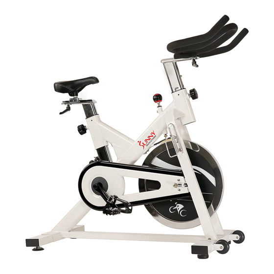
- Page 1 INDOOR CYCLING BIKE SF-B1110 USER MANUAL IMPORTANT! Read all instructions carefully before using this product. Retain owner’s manual for future reference. For customer service, please contact: support@sunnyhealthfitness.com...
-
Page 2: Important Safety Information
IMPORTANT SAFETY INFORMATION We thank you for choosing our product. To ensure your safety and health, please use this equipment correctly. It is important to read this entire manual before assembling and using the equipment. Safe and effective use can only be assured if the equipment is assembled, maintained, and used properly. -
Page 3: Exploded Drawing
EXPLODED DRAWING... -
Page 4: Parts List
PARTS LIST DESCRIPTION DESCRIPTION Screw M6*12*Φ12 End cap F80*40 Rear stabilizer Tension Knob M10 Foot levelers Nut M10 Washer d8*φ16*1.5 Brake rod φ10*210 Square nut Screw M8*55 Nut M6*H14*S10 Front stabilizer Brake board t7*138.3*28 Bolt M6*45 Spring piece t1.5*110*15.5 Bearing 608ZZ Woolen felt 9L/R Pedal... -
Page 5: Hardware Package
HARDWARE PACKAGE... -
Page 6: Assembly Instructions
ASSEMBLY INSTRUCTIONS STEP 1: Remove the Shipping Tubes (No. 69) from the Main Frame (No. 64) by unscrewing the Screws (No. 70) and Washers (No. 4) with the Allen Wrench (No. 75). NOTE: You may discard these parts or save them parts for future packaging and transportation {Screws (No. - Page 7 STEP 2: Attach the Front & Rear Stabilizers (No. 6 & No. 2) onto the Main Frame (No. 64) and attach using 4 Hex Screws (No. 5) and 4 Washers (No. 4).
- Page 8 STEP 3: Insert the Saddle Post (No. 30) into the Main Frame (No. 64) and fix using the [seat adjustment] Knob (No. 38). Secure the Saddle Column (No. 27) onto the Saddle Post (No. 30) using the L- shaped Knob (No. 29) and Washer (No. 28).
- Page 9 STEP 4: Insert the Handlebar Post (No. 36) into the Main Frame (No. 64) and fix with [handlebar adjustment] Knob (No. 38). Secure the Handlebar (No. 35) onto the Handlebar Post (No. 36) using the L- shaped Knob (No. 29) and Washer (No. 28).
- Page 10 39 67 68 STEP 5: WARNING! Read instructions carefully as improper assembly may cause permanent damage to your bike. Remove the 2 Nylon Nuts (No. 74 L/R) located on the Pedals (No. 9 L/R). Screw the Left Pedal (No. 9L) counter-clockwise into its corresponding Crank Shaft (No. 10L).
-
Page 11: Adjusting The Balance
ADJUSTMENTS GUIDE ADJUSTING THE BALANCE In order to achieve a smooth and comfortable ride, you must ensure that the stability of the bike is secured. If you notice that the bike is unbalanced during use, you should adjust the foot levelers located beneath the front and rear stabilizers. To do so, simply rotate the Foot Levelers (No. -
Page 12: Seat Adjustment
SEAT ADJUSTMENT An appropriate seat height helps to ensure your exercise efficiency and reduce the risk of injury. Adjusting the seat forward or backward can help you work out different body muscle groups. With one pedal in the upward position, place your foot in the toe clip and get on the bike. -
Page 13: Handlebar Adjustment
HANDLEBAR ADJUSTMENT Loosen the [handlebar adjustment] Knob (No. 38) to raise or lower the handlebar to the desired position. Make sure the Knob (No. 38) settles into the desired hole and secure it firmly by turning clockwise. See Figure A. Figure A Figure B Loosen the L-shaped Knob (No.
Need help?
Do you have a question about the SF-B1110 and is the answer not in the manual?
Questions and answers