Advertisement
Advertisement
Table of Contents

Related Manuals for Sherwood Scuba 9000 SERIES


Summary of Contents for Sherwood Scuba 9000 SERIES
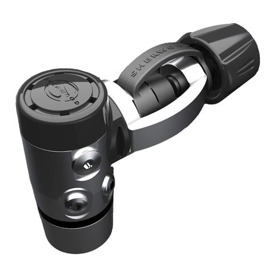
- Page 1 9000 SERIES FIRST STAGE...
- Page 2 Before attempting to perform service read this manual in its entirety. There are warnings and cautions contained in the manual that may affect your safety or the safety of the regulator user. If you are uncertain as to whether you are qualified to perform this service contact your regional Sherwood Scuba Distributor for technical assistance.
- Page 3 Regulators that are used in extreme conditions, such as commercial use or rentals require more frequent service over- hauls of at least every 3 to 6 months. Sherwood Scuba offers a standard service kit that contains the parts recommended to be replaced in connection with the standard service overhaul.
-
Page 4: General Comments
www.sherwoodscuba.com GENERAL COMMENTS NOTE – Read this section before attempting to perform service. Read the entire set of procedures that follows before starting to service. Steps taken out of sequence or without the knowledge of the proper procedure could damage the regulator or otherwise complicate the service process. Refer to the Illustrated Parts List while performing service. -
Page 5: Facility Requirements
www.sherwoodscuba.com ENRICHED AIR NITROX SERVICE The Sherwood regulator presented in this manual has been designed and manufactured to allow the use of Enriched Air Nitrox (EAN) gas with an oxygen component not to exceed 40%. In order to maintain this option the user must ensure that the regulator is protected from the introduction of hydrocarbons. - Page 6 9000 SERIES FIRST STAGE RECOMMENDED TOOLS AND SUPPLIERS The specialty tools identified below may be purchased from your Sherwood Scuba Distributor. Common tools are available from several sources. Common Tools Open End Wrenches - 9/16”, 5/8”,1/2” Box End Wrench – 3/4”...
-
Page 7: Disassembly Procedure
www.sherwoodscuba.com DISASSEMBLY PROCEDURE Record the First Stage and Second Stage serial numbers and an inventory of all attached accessories before beginning disassembly. Perform an inspection of the regulator in accordance with the Annual Inspection Guidelines. And take notes of the initial performance values when the regulator was received. This process will give the technician a reference point if after the overhaul the regulator does not perform as expected. - Page 8 www.sherwoodscuba.com Remove the Yoke Retainer, Inlet Protector (16) and Yoke (15). Use Snap Ring Pliers (PN 10-101-500) to compress and remove the Retaining Ring (25). Tip the Yoke Retainer and the Filter (8) and O-ring (17) will separate from the Yoke Retainer. Remove O-rings (13 & 17). Each of the O-rings in this subassembly will be cleaned and reused unless damaged.
- Page 9 www.sherwoodscuba.com 14. Peel the lip of the Diaphragm up and remove it from the First Stage Body. Discard the Diaphragm. A new part will be used in reassembly. 15. Use the Schrader Valve Tool (PN 12-100-500) to rotate the Schrader Valve (18) counterclockwise to remove it. Discard the valve.
-
Page 10: General Cleaning Procedure
www.sherwoodscuba.com GENERAL CLEANING PROCEDURE Thermoplastic, silicone rubber and anodized aluminum parts, such as diaphragms, accent trim, adjustment knobs, static O-rings, and thermoplastic housings. a. Soak in a solution of warm water and ordinary liquid dish detergent. Scrub with a soft nylon bristle brush to remove deposits. - Page 11 www.sherwoodscuba.com INSPECTION AND LUBRICATION PROCEDURES • Refer to the Illustrated Parts List (IPL) which provides information regarding which parts should be replaced during the reassembly. • Before beginning the reassembly process be certain to inspect all parts to be used. Each part must be clean and free of defects.
-
Page 12: Reassembly Procedures
www.sherwoodscuba.com REASSEMBLY PROCEDURES Place the Back-up Ring (22) over the small end of the installation tool (PN– 20-900-400) and insert the Back-up Ring into the First Stage Body (3) interior approaching from the end that receives the HP Orifice (11). Use the tool to firmly press the Back-up ring into the cavity for retaining it. - Page 13 www.sherwoodscuba.com Place the large end of the Orifice onto a blunt probe as a means to hold it for insertion into the First Stage Body. Carefully guide the Orifice into the high pressure side of the Body so that the nose of the Orifice fits into the installed Back-up Ring.
- Page 14 www.sherwoodscuba.com Install a new High Pressure Seat (10) into the cavity at the end of the piston stem. Check to be certain that it is even, fully seated and does not sit in an angle nor protrudes from the piston stem. 10.
- Page 15 www.sherwoodscuba.com 16. Use a vise padded with rubber or wood only. Secure the First Stage Body in a vise with the inlet port facing straight up. 17. Place the O-ring (17) over the conical end of the Filter (8) and insert the Filter into the Yoke Retainer. Use Retaining Ring Pliers compress the Retaining Ring (25) and install it into the Yoke Retainer.
- Page 16 www.sherwoodscuba.com 20. Using the 1” Socket (PN 20-155-500) and Torque wrench with the Socket Drive Extension (PN 20-156-50), tighten the Yoke Retainer to 25 ft-lbs (±1). 21. Place the opening of the Inlet Protector (16) over the threads of the Handwheel (32) with the dimple in the Inlet Protector facing upward and thread the Handwheel into the Yoke.
-
Page 17: Final Testing Procedures
www.sherwoodscuba.com FINAL TESTING PROCEDURES CAUTION – If the regulator has been upgraded for use with EAN/NITROX, it is important to pressurize and flow test the regulator using only hydrocarbon-free gas. The regulator may otherwise become contaminated with hydrocarbons if normal compressed air is used. INTERMEDIATE PRESSURE TEST Connect a calibrated intermediate pressure test gauge to the regulator, either with a quick-disconnect inflator hose or with the female fitting of a second stage LP hose, depending on the connection of the test gauge. - Page 18 www.sherwoodscuba.com AMBIENT PRESSURE VALVE TEST After the first stage exhibits a stable intermediate pressure of 140 (±10) psi with no creep, perform the following test check the function of the ambient sensing diaphragm and valve, using the Pressure Tool (PN 20-650-400). Install the Pressure Test Tool over the end of the Saddle that covers the first stage diaphragm.
- Page 19 www.sherwoodscuba.com TABLE 1 TROUBELSOOTING GUIDE SYMPTOM POSSIBLE CAUSE TREATMENT Excessive inhalation resistance 1. Cylinder valve partially opened. 1. Fully open valve, then turn back from both first & second stages 2. Cylinder valve requires service. ¼ turn. Check fill pressure. 3.
- Page 20 www.sherwoodscuba.com 9000 FIRST STAGE ITEM PART # DESCRIPTION SHV7035 Piston SHV7036 End Cap SHV7037 Body First Stage SHV7038 Yoke Retainer SHV7039 LP Port Plug SHV7040 Styling Ring SHV7041 Saddle SHV7042 Filter SHV7043 Orifice Retainer SHV7044 HP Seat SHV7048 Orifice SHV7049 Spring Washer SHV7061 O-ring...
Need help?
Do you have a question about the 9000 SERIES and is the answer not in the manual?
Questions and answers