Table of Contents
Advertisement
Advertisement
Table of Contents

Related Manuals for Ironton 49381


Summary of Contents for Ironton 49381
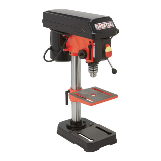
- Page 1 8" Benchtop Drill Press Owner’s Manual WARNING: Read carefully and understand all ASSEMBLY AND OPERATION INSTRUCTIONS before operating. Failure to follow the safety rules and other basic safety precautions may result in serious personal injury. Item #49381 SAVE THESE INSTRUCTIONS...
- Page 2 Thank you very much for choosing an Ironton product! For future reference, please complete the owner’s record below: Serial Number/Lot Date Code: ________________________________ Purchase Date: ____________________________________________ Save the receipt, warranty, and this manual. It is important that you read the entire manual to become familiar with this product before you begin using it.
-
Page 3: Table Of Contents
Table of Contents Intended Use ............................4 Technical Specifications ........................4 Important Safety Considerations ......................5 Specific Operation Warnings ....................... 9 Grounding ............................11 Extension Cords ..........................12 Assembly ............................. 13 Before Each Use ..........................16 Operating Instructions ........................19 After Each Use ............................. -
Page 4: Intended Use
Intended Use The drill press includes five speeds for drilling holes on cast iron, steel, aluminum, wood, etc. The machine has been designed for indoor use and must be used only in dry conditions. Technical Specifications Property Specification Voltage / Frequency: 120V / 60Hz Motor Power 1/3 HP... -
Page 5: Important Safety Considerations
Important Safety Considerations Read and understand all instructions. Failure to follow all instructions may result in serious injury. The warnings, cautions, and instructions in this manual cannot cover all possible conditions or situations that could occur. Exercise common sense and caution when using the drill press. Always be aware of the environment and ensure that the drill press is used in a safe and responsible manner. - Page 6 WORK AREA SAFETY Inspect the work area before each use. Keep work area clean, dry, free of clutter, and well lit. Cluttered, wet, or dark work areas can result in injury. Using the tool in confined work areas may put you dangerously close to other cutting tools and rotating parts.
- Page 7 ELECTRICAL SAFETY Grounded tools must be plugged into an outlet properly installed and grounded in accordance with all codes and ordinances. Never remove the grounding prong or modify the plug in any way. Do not use any adapter plugs. Check with a qualified electrician if you are in doubt as to whether the outlet is properly grounded.
- Page 8 DRILL PRESS USE AND CARE Do not force the tool. Tools do a better and safer job when used in the manner for which they are designed. Plan your work, and use the correct tool for the job. Check for damaged parts before each use.
-
Page 9: Specific Operation Warnings
Specific Operation Warnings GENERAL SAFETY INSTRUCTIONS To avoid mistakes that could cause serious injury, do not plug the Drill Press in until you have read and understood the following: USE PROPER EXTENSION CORDS. Make sure your extension cord is in good condition. When using an extension cord, be sure to use one heavy enough to carry the current your product will draw. - Page 10 BEFORE STARTING the operation, jog the motor switch to make sure the drill bit does not wobble or vibrate. LET THE SPINDLE REACH FULL SPEED before starting to drill. If your drill press makes an unfamiliar noise or if it vibrates excessively, stop immediately, turn the drill press OFF and unplug. Do not restart the unit until the problem is corrected.
-
Page 11: Grounding
Grounding This machine must be grounded while in use to protect the operator from electrical shock. This drill press is equipped with an electric cord that has an equipment-grounding conductor and a grounding plug. The plug MUST be plugged into a matching receptacle that is properly installed and grounded in accordance with ALL local codes and ordinances. -
Page 12: Extension Cords
Extension Cords USE A PROPER EXTENSION CORD. Make sure your extension cord is in good condition. When using an extension cord, be sure to use one heavy enough to carry the current your product will draw. An undersized cord will cause a drop in line voltage, resulting in loss of power and cause overheating. -
Page 13: Assembly
Assembly For your own safety, do not try to plug in the drill press until it is completely assembled and installed according to the instructions and until you have read and understood this instruction manual. To avoid injury from unexpected starting, do not plug the power cord into a power source receptacle during unpacking and assembly. - Page 14 2. Position the base on the floor or a bench. Attach the column assembly to base using hex bolts 3. Slide the table assembly onto the column and tighten the locking handle to secure the table. 3. Install the head assembly 3.1 Carefully lift the head above the column and slide it onto the column.
- Page 15 6. Install the chuck 6.1 Tilt the chuck guard to the open position and push the chuck onto the spindle. 6.2 Using a wood mallet, firmly tap the chuck upward into position on the spindle shaft. 7. Install the depth stop assembly (not included) Slide the end of the threaded rod through the bracket on the side of the head, then through the hole in the top of the chuck guard.
-
Page 16: Before Each Use
Before Each Use To avoid injury from accidental starting, always turn the switch OFF and unplug the drill press before installing or removing any accessory or attachment or making any adjustment. Make the following adjustments before each use of the drill press. 1. - Page 17 2. Feed Depth Adjustment Lower the spindle assembly to a desired depth and turn down the adjust nut. Turn down the lock nut against the adjust nut to lock it in place. The drill is now set to drill holes to this predetermined depth.
- Page 18 4.2 While firmly holding the spring housing: a. Pull out the housing and rotate it (counter-clockwise to increase or clockwise to decrease the spring tension) until the boss D is engaged with the next notch on the housing. b. Turn nut B until it contacts the spring housing, then back off about 1/4 turn. ATTENTION: The inside of nut B should not contact spring housing when done.
-
Page 19: Operating Instructions
Operating Instructions To avoid injury from accidental starting, always turn the switch OFF and unplug the drill press before installing or removing any accessory or attachment or making any adjustment. Always wear safety goggles when operating the drill. Use only accessories designed for this machine to avoid injury from thrown broken parts. ... - Page 20 2. Positioning the Workpiece To prevent the workpiece or backing piece from tearing from your hands while drilling, you MUST position it against the LEFT side of the column. Failure to do this could result in personal injury. 3. Using a Vise For a small workpiece that cannot be clamped to the table, use a drill press vise.
-
Page 21: After Each Use
After Each Use After each use, Disconnect the power cord Clear the scrap iron Clean the surface Add anti-rust oil onto the metal surface of workbench, baseboard, column and main spindle quill Page 21 of 29... -
Page 22: Maintenance
Maintenance TO AVOID INJURY from accidental starting, always turn the power switch OFF and unplug the drill press before installing or removing any accessory or attachment or making any adjustment. MAINTAIN TOOLS WITH CARE. Keep tools sharp and clean for best and safest performance. Follow instructions for lubricating and changing accessories. -
Page 23: Parts Diagram
Parts Diagram Page 23 of 29... -
Page 24: Parts List
Parts List Description Q'ty Description Q'ty 31B- Belt Switch Cover (two holes) Motor Pulley 31C- 4.2 x 12mm Cross Recess Pan Head 8 x 10mm Hex Socket Set Screw Tapping Screw 31C- Self-locking Switch Heart 31C- 6mm Hex Nut Self-locking Switch Plate 31C- 6mm Flat Washer Switch Box (two holes) - Page 25 6203Z Bearing 6 x 15 x 2 Rubber Washer 3BMI-40 Retaining Ring 6mm Flat Washer 5 X 16mm Cross Recess Pan Head 6 x 12mm Cross Recess Pan Head Screw Screw 5mm Flat Washer 8mm Hex Nut Line Cord clamp Motor Connecting Plate 5mm Flat Washer 8mm Flat Washer...
- Page 26 Reference List of Drill, Revolution and Various Materials Page 26 of 29...
-
Page 27: Troubleshooting
Troubleshooting Replacement Parts For replacement parts and technical questions, please call Customer Service at 1-800-222-5381. Not all product components are available for replacement. The illustrations provided are a convenient reference to the location and position of parts in the assembly sequence. ... -
Page 28: Limited Warranty
Northern Tool and Equipment Company, Inc. ("We'' or '"Us'') warrants to the original purchaser only ("You'' or “Your”) that the Ironton product purchased will be free from material defects in both materials and workmanship, normal wear and tear excepted, for a period of one year from date of purchase. - Page 29 Distributed by Northern Tool and Equipment Company, Inc. Burnsville, Minnesota 55306 NorthernTool.com Made in China Page 29 of 29...
Need help?
Do you have a question about the 49381 and is the answer not in the manual?
Questions and answers