Table of Contents
Advertisement
Quick Links
Advertisement
Table of Contents
Troubleshooting

Related Manuals for Delta VFD-E


Summary of Contents for Delta VFD-E
- Page 4 Ground the VFD-E using the ground terminal. The grounding method must comply with the laws of the country where the AC motor drive is to be installed. Refer to the Basic Wiring Diagram. VFD-E series is used only to control variable speed of 3-phase induction motors, NOT for 1- phase motors or other purpose.
- Page 5 WARNING! DO NOT use Hi-pot test for internal components. The semi-conductor used in AC motor drive easily damage by high-voltage. There are highly sensitive MOS components on the printed circuit boards. These components are especially sensitive to static electricity. To prevent damage to these components, do not touch these components or the circuit boards with metal objects or your bare hands.
-
Page 6: Table Of Contents
Table of Contents Preface ......................i Table of Contents ..................iii Chapter 1 Introduction ................1-1 1.1 Receiving and Inspection ..............1-2 1.1.1 Nameplate Information..............1-2 1.1.2 Model Explanation ..............1-2 1.1.3 Series Number Explanation ............1-3 1.1.4 Drive Frames and Appearances ..........1-3 1.1.5 Remove Instructions .............. -
Page 7: Table Of Contents
Chapter 3 Keypad and Start Up ..............3-1 3.1 Keypad ....................3-1 3.2 Operation Method ................3-2 3.3 Trial Run .....................3-3 Chapter 4 Parameters..................4-1 4.1 Summary of Parameter Settings............4-2 4.2 Parameter Settings for Applications..........4-33 4.3 Description of Parameter Settings ............4-38 4.4 Different Parameters for VFD*E*C Models ........4-181 Chapter 5 Troubleshooting .................5-1 5.1 Over Current (OC) ................5-1 5.2 Ground Fault..................5-2... -
Page 8: Table Of Contents
Chapter 6 Fault Code Information and Maintenance........ 6-1 6.1 Fault Code Information ............... 6-1 6.1.1 Common Problems and Solutions..........6-1 6.1.2 Reset ..................6-6 6.2 Maintenance and Inspections............. 6-6 Appendix A Specifications ................ A-1 Appendix B Accessories ................B-1 B.1 All Brake Resistors & Brake Units Used in AC Motor Drives....B-1 B.1.1 Dimensions and Weights for Brake Resistors ...... -
Page 9: Table Of Contents
B.8 KPE-LE02..................B-21 B.8.1 Description of the Digital Keypad KPE-LE02 ......B-21 B.8.2 How to Operate the Digital Keypad...........B-23 B.8.3 Reference Table for the 7-segment LED Display of the Digital Keypad ....................B-24 B.8.4 Keypad Dimensions ..............B-24 B.9 Extension Card................B-25 B.9.1 Relay Card................B-25 B.9.2 Digital I/O Card .................B-26 B.9.3 Analog I/O Card ................B-26 B.9.4 Communication Card ..............B-26... -
Page 10: Table Of Contents
B.10.3 Profibus Communication Module (CME-PD01) ...... B-31 B.10.3.1 Panel Appearance ............B-32 B.10.3.2 Dimensions ..............B-33 B.10.3.3 Parameters Settings in VFD-E........B-33 B.10.3.4 Power Supply..............B-33 B.10.3.5 PROFIBUS Address ............B-33 B.10.4 CME-COP01 (CANopen)............B-34 B.10.4.1 Product Profile ..............B-34 B.10.4.2 Specifications.............. -
Page 11: Table Of Contents
D.2.1 The Steps for PLC Execution ............ D-2 D.2.2 Device Reference Table ............D-3 D.2.3 WPLSoft Installation ..............D-4 D.2.4 Program Input ................D-4 D.2.5 Program Download ..............D-5 D.2.6 Program Monitor ................ D-5 D.2.7 The Limit of PLC ................ D-5 D.3 Ladder Diagram ................ -
Page 12: Table Of Contents
D.5 Commands ..................D-27 D.5.1 Basic Commands ..............D-27 D.5.2 Output Commands ..............D-28 D.5.3 Timer and Counters..............D-28 D.5.4 Main Control Commands............D-28 D.5.5 Rising-edge/falling-edge Detection Commands of Contact ..D-28 D.5.6 Rising-edge/falling-edge Output Commands......D-29 D.5.7 End Command .................D-29 D.5.8 Explanation for the Commands ..........D-29 D.5.9 Description of the Application Commands........D-44 D.5.10 Explanation for the Application Commands......D-45 D.5.11 Special Application Commands for the AC Motor Drive ..D-57... - Page 13 This page intentionally left blank...
-
Page 14: Chapter 1 Introduction
Chapter 1 Introduction The AC motor drive should be kept in the shipping carton or crate before installation. In order to retain the warranty coverage, the AC motor drive should be stored properly when it is not to be used for an extended period of time. -
Page 15: Receiving And Inspection
Chapter 1 Introduction| 1.1 Receiving and Inspection This VFD-E AC motor drive has gone through rigorous quality control tests at the factory before shipment. After receiving the AC motor drive, please check for the following: Check to make sure that the package includes an AC motor drive, the User Manual/Quick Start and CD. -
Page 16: Series Number Explanation
Chapter 1 Introduction| 1.1.3 Series Number Explanation 007E23A 1230 Pro du ction n um ber Pro du ction w eek Pro du ction year 2008 Pro du ction f act ory T: Taoyu an, W: Wu jian g 230V 3- ph ase 1HP (0.75kW ) Mo del If the nameplate information does not correspond to your purchase order or if there are any problems, please contact your distributor. - Page 17 Chapter 1 Introduction| 1-5HP/0.75-3.7kW (Frame B) Input terminals (R/L1, S/L2, T/L3) Keypad cover Case body Control board cover Output terminals (U/T1, V/T2, W/T3) 7.5-15HP/5.5-11kW (Frame C) Input terminals (R/L1, S/L2, T/L3) Case body Keypad cover Control board cover Output terminals (U/T1, V/T2, W/T3) 20-30HP/15-22kW (Frame D) Input terminals...
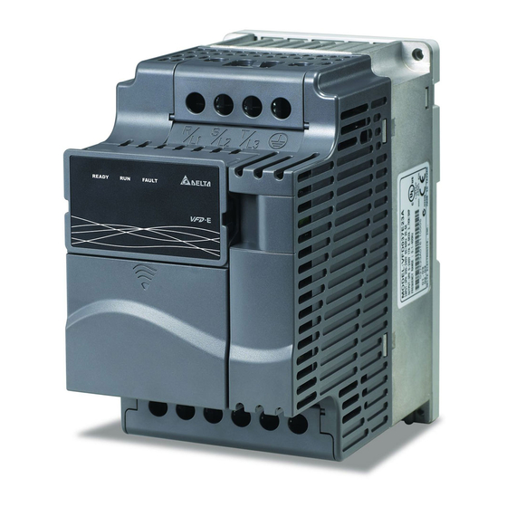
- Page 18 Chapter 1 Introduction| Internal Structure READY: power indicator RUN: status indicator FAULT: fault indicator Switch to ON for 50Hz, refer to P 01.00 to P01.02 for details Switch to ON for free run to stop refer to P02.02 Switch to ON for setting frequency source to ACI (P 02.00=2) ACI terminal (ACI/AVI2 switch ) NPN/PNP...
- Page 19 Chapter 1 Introduction| Frame B: above the nameplate Frame C: above the warning label Frame D: near the input terminals (R/L1, S/L2, T/L3) Frame Power range Models VFD002E11A/21A/23A, VFD004E11A/21A/23A/43A, VFD007E21A/23A/43A, VFD015E23A/43A VFD002E11C/21C/23C, VFD004E11C/21C/23C/43C, A (A1) 0.25-2hp (0.2-1.5kW) VFD007E21C/23C/43C, VFD015E23C/43C VFD002E11T/21T/23T, VFD004E11T/21T/23T/43T, VFD007E21T/23T/43T, VFD015E23T/43T VFD002E11P/21P/23P, VFD004E11P/21P/23P/43P, A (A2)
-
Page 20: Remove Instructions
Chapter 1 Introduction| RFI Jumper RFI Jumper: The AC motor drive may emit the electrical noise. The RFI jumper is used to suppress the interference (Radio Frequency Interference) on the power line. Main power isolated from earth: If the AC motor drive is supplied from an isolated power (IT power), the RFI jumper must be cut off. Then the RFI capacities (filter capacitors) will be disconnected from ground to prevent circuit damage (according to IEC 61800-3) and reduce earth leakage current. - Page 21 Chapter 1 Introduction| Remove Keypad Remove Front Cover Press and hold in the tabs on each side of the cover. Pull the cover up to release. Step 1 Step 2 Remove RST Terminal Cover Remove UVW Terminal Cover For Frame B, Frame C and Frame D: it only For Frame B, Frame C and Frame D: it only needs to turn the cover lightly to open it needs to turn the cover light to open the cover...
-
Page 22: Preparation For Installation And Wiring
Chapter 1 Introduction| 1.2 Preparation for Installation and Wiring 1.2.1 Ambient Conditions Install the AC motor drive in an environment with the following conditions: -10 ~ +50°C (14 ~ 122°F) for UL & cUL Air Temperature: -10 ~ +40°C (14 ~ 104°F) for side-by-side mounting Relative Humidity: <90%, no condensation allowed Atmosphere... - Page 23 Frame B, C and D Mounting Clearances Single drive Side-by-side installation Air flow 150mm 150mm Air Flow 150mm 150mm For VFD-E-P series: heat sink system example Air-extracting apparatus User 's heat sink should comply with following conditions: Control panel Duct temperature Air flow speed 2m/sec 1.
- Page 24 Chapter 1 Introduction| The heat sink temperature may rise to 90°C when running. The material on which the AC motor drive is mounted must be noncombustible and be able to withstand this high temperature. When AC motor drive is installed in a confined space (e.g. cabinet), the surrounding temperature must be within 10 ~ 40°C with good ventilation.
-
Page 25: Parallel
Chapter 1 Introduction| 1.2.2 DC-bus Sharing: Connecting the DC-bus of the AC Motor Drives in Parallel This function is not for VFD-E-T series. The AC motor drives can absorb mutual voltage that generated to DC bus when deceleration. Enhance brake function and stabilize the voltage of the DC bus. -
Page 26: Dimensions
Chapter 1 Introduction| 1.3 Dimensions (Dimensions are in millimeter and [inch]) Frame A Unit: mm [inch] Frame 72.0 60.0 142.0 120.0 152.0 50.0 A (A1) [2.83] [2.36] [5.59] [4.72] [5.98] [1.97] [0.18] [0.20] [0.20] 72.0 56.0 155.0 143.0 111.5 A (A2) [2.83] [2.20] [6.10]... - Page 27 Chapter 1 Introduction| Frame B Unit: mm [inch] Frame 100.0 89.0 174.0 162.0 152.0 50.0 [3.94] [3.50] [6.86] [6.38] [5.98] [1.97] [0.16] [0.22] [0.22] NOTE Frame B (B1): VFD007E11A, VFD015E21A, VFD022E21A/23A/43A, VFD037E23A/43A, VFD007E11C, VFD015E21C, VFD022E21C/23C/43C, VFD037E23C/43C 1-14 Revision Jan. 2009, 06EE, SW--PW V1.12/CTL V2.12...
- Page 28 Chapter 1 Introduction| Frame C Unit: mm [inch] Frame 130.0 116.0 260.0 246.5 169.2 78.5 [5.12] [4.57] [10.24] [9.70] [6.66] [3.09] [0.31] [0.26] [0.22] NOTE Frame C (C1): VFD055E23A/43A, VFD075E23A/43A, VFD110E23A/43A, VFD055E23C/43C, VFD075E23C/43C, VFD110E23C/43C Revision Jan. 2009, 06EE, SW--PW V1.12/CTL V2.12 1-15...
- Page 29 Chapter 1 Introduction| Frame D Unit: mm [inch] Frame 200.0 180.0 310.0 290.0 190.0 92.0 10.0 10.0 [7.87] [7.09] [12.20] [11.42] [7.48] [3.62] [0.39] [0.39] [0.35] NOTE Frame D (D1): VFD150E23A/23C, VFD150E43A/43C, VFD185E43A/43C, VFD220E43A/43C 1-16 Revision Jan. 2009, 06EE, SW--PW V1.12/CTL V2.12...
-
Page 30: Chapter 2 Installation And Wiring
The "Line Fuse Specification" in Appendix B, lists the recommended fuse part number for each VFD-E Series part number. These fuses (or equivalent) must be used on all installations where compliance with U.L. standards is a required. -
Page 31: Wiring
Chapter 2 Installation and Wiring| DANGER! A charge may still remain in the DC bus capacitors with hazardous voltages even if the power has been turned off. To prevent personal injury, please ensure that the power is turned off and wait ten minutes for the capacitors to discharge to safe voltage levels before opening the AC motor drive. - Page 32 Chapter 2 Installation and Wiring| Figure 1 for models of VFD-E Series VFD002E11A/21A, VFD004E11A/21A, VFD007E21A, VFD002E11C/21C, VFD004E11C/21C, VFD007E21C, VFD002E11P/21P, VFD004E11P/21P, VFD007E21P brake resi stor (opti onal) brake unit ( optional) F us e/NF B(None F use Br eaker) Motor R(L1)
- Page 33 Chapter 2 Installation and Wiring| Figure 2 for models of VFD-E Series VFD002E23A, VFD004E23A/43A, VFD007E23A/43A, VFD015E23A/43A, VFD002E23C, VFD004E23C/43C, VFD007E23C/43C, VFD015E23C/43C, VFD002E23P, VFD004E23P/43P, VFD007E23P/43P, VFD015E23P/43P brake resi stor (opti onal) brake unit ( optional) F us e/NF B(No F use B reaker)
- Page 34 Chapter 2 Installation and Wiring| Figure 3 for models of VFD-E Series VFD007E11A, VFD015E21A, VFD022E21A, VFD007E11C, VFD015E21C, VFD022E21C brake resi stor (opti onal) F us e/NF B(No F use B reaker) +/B1 Motor R(L1) R(L1) U(T 1) S(L2) S(L2) V(T2)
- Page 35 Chapter 2 Installation and Wiring| Figure 4 for models of VFD-E Series VFD022E23A/43A, VFD037E23A/43A, VFD055E23A/43A, VFD075E23A/43A, VFD110E23A/43A, VFD022E23C/43C, VFD037E23C/43C, VFD055E23C/43C, VFD075E23C/43C, VFD110E23C/43C, VFD150E23A/23C, VFD150E43A/43C, VFD185E43A/43C, VFD220E43A/43C brake resi stor (opti onal) F us e/NF B(No F use B reaker) +/B1...
- Page 36 Chapter 2 Installation and Wiring| Figure 5 for models of VFD-E Series VFD002E11T/21T, VFD004E11A/21T, VFD007E21T brake resi stor (opti onal) F us e/NF B(No F use B reaker) Motor R(L1) R(L1) U(T 1) S(L2) S(L2) V(T2) Recommended Circuit W(T 3)
- Page 37 Chapter 2 Installation and Wiring| Figure 6 for models of VFD-E Series VFD002E23T, VFD004E23T/43T, VFD007E23T/43T, VFD015E23T/43T brake resi stor (opti onal) F us e/NF B(No F use B reaker) Motor R(L1) R(L1) U(T1) S(L2) S(L2) V(T2) T(L3) T( L3) W(T 3)
- Page 38 Chapter 2 Installation and Wiring| Figure 7 Wiring for NPN mode and PNP mode A. NPN mode without external power Factory setting B. NPN mode with external power Factory setting C. PNP mode without external power Factory setting Revision Jan. 2009, 06EE, SW--PW V1.12/CTL V2.12...
- Page 39 Chapter 2 Installation and Wiring| D. PNP mode with external power Factory setting Figure 8 RJ-45 pin definition for VFD*E*C models Signal Description CAN_H CAN_H bus line (dominant high) CAN_L CAN_L bus line (dominant low) CAN_GND Ground / 0V /V- 485 communication 485 communication CAN_GND...
- Page 40 Use ground leads that comply with local regulations and keep them as short as possible. No brake resistor is built in the VFD-E series, it can install brake resistor for those occasions that use higher load inertia or frequent start/stop. Refer to Appendix B for details.
-
Page 41: External Wiring
Chapter 2 Installation and Wiring| 2.2 External Wiring Items Explanations Power Supply Please follow the specific power Power supply requirements shown in supply Appendix A. There may be an inrush current during power up. Please check the FUSE/NFB Fuse/NFB chart of Appendix B and select the (Optional) correct fuse with rated current. -
Page 42: Main Circuit
Chapter 2 Installation and Wiring| 2.3 Main Circuit 2.3.1 Main Circuit Connection Figure 1 For frame A: VFD002E11A/21A/23A, VFD004E11A/21A/23A/43A, VFD007E21A/23A/43A, VFD015E23A/43A, VFD002E11C/21C/23C, VFD004E11C/21C/23C/43C, VFD007E21C/23C/43C, VFD002E11P/21P/23P, VFD004E11P/21P/23P/43P, VFD007E11P/21P/23P/43P, VFD015E23P/43P Brake Resistor(Optional) Brake Unit (Optional) No fuse breaker (NFB) Motor R(L1) U(T1) S(L2) V(T2) T(L3) - Page 43 Chapter 2 Installation and Wiring| Terminal Symbol Explanation of Terminal Function R/L1, S/L2, T/L3 AC line input terminals (1-phase/3-phase) U/T1, V/T2, W/T3 AC drive output terminals for connecting 3-phase induction motor +/B1~ B2 Connections for Brake resistor (optional) +/B1, - Connections for External Brake unit (BUE series) Earth connection, please comply with local regulations.
- Page 44 When it needs to install the filter at the output side of terminals U/T1, V/T2, W/T3 on the AC motor drive. Please use inductance filter. Do not use phase-compensation capacitors or L-C (Inductance-Capacitance) or R-C (Resistance-Capacitance), unless approved by Delta. DO NOT connect phase-compensation capacitors or surge absorbers at the output terminals of AC motor drives.
-
Page 45: Main Circuit Terminals
Chapter 2 Installation and Wiring| 2.3.2 Main Circuit Terminals Frame A Main circuit terminals: R/L1, S/L2, T/L3, U/T1, V/T2, W/T3, , +, - Models Wire Torque Wire type VFD002E11A/21A/23A VFD004E11A/21A/23A/ VFD007E21A/23A/43A VFD015E23A/43A VFD002E11C/21C/23C VFD004E11C/21C/23C/ VFD007E21C/23C/43C Stranded 12-14 AWG. VFD015E23C/43C 14kgf-cm copper (3.3- (12in-lbf) -
Page 46: Control Terminals
Chapter 2 Installation and Wiring| Frame C Main circuit terminals: R/L1, S/L2, T/L3, U/T1, V/T2, W/T3, , +/B1, B2, - Models Wire Torque Wire type VFD055E23A/43A, VFD075E23A/43A, Stranded VFD110E23A/43A, 30kgf-cm 6-16 AWG. copper (13.3-1.3mm (26in-lbf) VFD055E23C/43C, Only, 75℃ VFD075E23C/43C, VFD110E23C/43C NOTE To connect 6 AWG (13.3 mm ) wires, use Recognized Ring... - Page 47 Chapter 2 Installation and Wiring| The position of the control terminals AFM MCM MO1 RS-485 DCM 24V ACM AVI ACI MI1 MI2 MI3 MI4 MI5 MI6 Terminal symbols and functions Factory Settings (NPN mode) Terminal Terminal Function Symbol ON: Connect to DCM Run in MI1 direction Forward-Stop command OFF:...
- Page 48 Chapter 2 Installation and Wiring| Factory Settings (NPN mode) Terminal Terminal Function Symbol ON: Connect to DCM Maximum 48VDC, 50mA Refer to Pr.03.01 for programming Max: 48Vdc MO1-DCM 50mA Multi-function Output 1 (Photocoupler) internal circuit Multi-function output common Common for Multi-function Outputs +10V Potentiometer power supply +10VDC 3mA...
- Page 49 Chapter 2 Installation and Wiring| Analog inputs (AVI, ACI, ACM) Analog input signals are easily affected by external noise. Use shielded wiring and keep it as short as possible (<20m) with proper grounding. If the noise is inductive, connecting the shield to terminal ACM can bring improvement. If the analog input signals are affected by noise from the AC motor drive, please connect μ...
- Page 50 Chapter 2 Installation and Wiring| The position of the control terminals Terminals 1 AFM MCM MO1 Terminals 2 RS-485 port DCM 24V ACM AVI ACI MI1 MI2 MI3 MI4 MI5 MI6 Frame Control Terminals Torque Wire Terminals 1 5 kgf-cm (4.4 in-lbf) 12-24 AWG (3.3-0.2mm A, B, C Terminals 2...
- Page 51 Chapter 2 Installation and Wiring| This page intentionally left blank 2-22 Revision Jan. 2009, 06EE, SW--PW V1.12/CTL V2.12...
-
Page 52: Chapter 3 Keypad And Start Up
Chapter 3 Keypad and Start Up Make sure that the wiring is correct. In particular, check that the output terminals U/T1, V/T2, W/T3. are NOT connected to power and that the drive is well grounded. Verify that no other equipment is connected to the AC motor drive Do NOT operate the AC motor drive with humid hands. -
Page 53: Operation Method
Chapter 3 Keypad and Start Up| 3.2 Operation Method The operation method can be set via communication, control terminals and optional keypad KPE- LE02. RS485 port (RJ-45) It needs to use VFD-USB01 or IFD8500 converter to connect to the PC. Revision Jan. -
Page 54: Trial Run
Chapter 3 Keypad and Start Up| Operation Operation Command Frequency Source Method Source When setting communication by the PC, it needs to use VFD-USB01 or Operate from the IFD8500 converter to connect to the PC. communication Refer to the communication address 2000H and 2101H setting for details. +24V FWD/Stop Factory setting:... - Page 55 Chapter 3 Keypad and Start Up| Setting the potentiometer or AVI-DCM 0-10Vdc power to less than 1V. Setting MI1=On for forward running. And if you want to change to reverse running, you should set MI2=On. And if you want to decelerate to stop, please set MI1/MI2=Off. Check following items: Check if the motor direction of rotation is correct.
-
Page 56: Chapter 4 Parameters
Chapter 4 Parameters The VFD-E parameters are divided into 14 groups by property for easy setting. In most applications, the user can finish all parameter settings before start-up without the need for re-adjustment during operation. The 14 groups are as follows:... -
Page 57: Summary Of Parameter Settings
Chapter 4 Parameters| 4.1 Summary of Parameter Settings : The parameter can be set during operation. Group 0 User Parameters Factory Parameter Explanation Settings Customer Setting 00.00 Identity Code of the Read-only AC motor drive 00.01 Rated Current Read-only Display of the AC motor drive 0: Parameter can be read/written 1: All parameters are read only... - Page 58 Chapter 4 Parameters| Factory Parameter Explanation Settings Customer Setting 5: Display PID analog feedback signal value (b) (%) 6: Output power factor angle (n) 7: Display output power (P) 8: Display the estimated value of torque as it relates to current (t) 9: Display AVI (I) (V) 10: Display ACI / AVI2 (i) (mA/V) 11: Display the temperature of IGBT (h) (°C)
- Page 59 Chapter 4 Parameters| Factory Parameter Explanation Settings Customer Setting Maximum Voltage 01.01 Frequency (Fbase) 0.10 to 600.0 Hz 60.00 (Motor 0) Maximum Output 115V/230V series: 0.1V to 255.0V 220.0 01.02 Voltage (Vmax) 460V series: 0.1V to 510.0V 440.0 (Motor 0) Mid-Point Frequency 01.03 0.10 to 600.0 Hz...
- Page 60 Chapter 4 Parameters| Factory Parameter Explanation Settings Customer Setting Acceleration S- 01.17 0.0 to 10.0 / 0.00 to 10.00 sec Curve Deceleration S- 01.18 0.0 to 10.0 / 0.00 to 10.00 sec Curve 0: Unit: 0.1 sec Accel/Decel Time 01.19 Unit 1: Unit: 0.01 sec 0.00 to 600.00 sec...
- Page 61 Chapter 4 Parameters| Factory Parameter Explanation Settings Customer Setting Maximum Output 115V/230V series: 0.1V to 255.0V 220.0 01.33 Voltage (Vmax) 460V series: 0.1V to 510.0V 440.0 (Motor 2) Mid-Point 0.10 to 600.0 Hz 01.34 Frequency (Fmid) 1.50 (Motor 2) 115V/230V series: 0.1V to 255.0V 10.0 Mid-Point Voltage 01.35...
- Page 62 Chapter 4 Parameters| Group 2 Operation Method Parameters Factory Parameter Explanation Settings Customer Setting 0: Digital keypad UP/DOWN keys or Multi- function Inputs UP/DOWN. Last used frequency saved. Source of First 1: 0 to +10V from AVI 02.00 Master Frequency 2: 4 to 20mA from ACI or 0 to +10V from Command AVI2...
- Page 63 Chapter 4 Parameters| Factory Parameter Explanation Settings Customer Setting 2: Disable. Operation status will change if operation command source Pr.02.01 is changed. 3: Enable. Operation status will change if operation command source Pr.02.01 is changed. 0: Decelerate to 0 Hz Loss of ACI Signal 1: Coast to stop and display “AErr”...
- Page 64 Chapter 4 Parameters| Factory Parameter Explanation Settings Customer Setting 0: Save Keypad & Communication The Selections for Frequency Saving Keypad or 1: Save Keypad Frequency only 02.13 Communication Frequency Command 2: Save Communication Frequency only 0: by Current Freq Command Initial Frequency Selection (for 02.14...
- Page 65 Chapter 4 Parameters| Factory Parameter Explanation Settings Customer Setting 5: Base-Block (B.B.) indication Multi-function 03.01 Output Terminal 6: Low-voltage indication 7: Operation mode indication 8: Fault indication 9: Desired frequency 1 attained 10: Terminal count value attained 11: Preliminary count value attained 12: Over Voltage Stall supervision 13: Over Current Stall supervision 14: Heat sink overheat warning...
- Page 66 Chapter 4 Parameters| Factory Parameter Explanation Settings Customer Setting 1: 1 minute after AC motor drive stops, fan will be OFF 2: Fan ON when AC motor drive runs, fan OFF when AC motor drive stops 3: Fan ON when preliminary heatsink temperature attained Read only Bit0=1:RLY used by PLC...
- Page 67 Chapter 4 Parameters| Group 4 Input Function Parameters Factory Parameter Explanation Settings Customer Setting Keypad 04.00 0.0 to 100.0 % Potentiometer Bias Keypad 0: Positive bias 04.01 Potentiometer Bias 1: Negative bias Polarity Keypad 04.02 0.1 to 200.0 % 100.0 Potentiometer Gain Keypad 0: No negative bias command...
- Page 68 Chapter 4 Parameters| Factory Parameter Explanation Settings Customer Setting 15: PID function disabled 16: Output shutoff stop 17: Parameter lock enable 18: Operation command selection (external terminals) 19: Operation command selection(keypad) 20: Operation command selection (communication) 21: FWD/REV command 22: Source of second frequency command 23: Run/Stop PLC Program (PLC1) (NOT for VFD*E*C models) 23: Quick Stop (Only for VFD*E*C models)
- Page 69 Chapter 4 Parameters| Factory Parameter Explanation Settings Customer Setting Min AVI Voltage 0.0 to 10.0V 04.11 0.0 to 100.0% Min AVI Frequency 04.12 Max AVI Voltage 0.0 to 10.0V 04.13 10.0 Max AVI Frequency 0.0 to 100.0% 04.14 100.0 Min ACI Current 0.0 to 20.0mA 04.15 0.0 to 100.0%...
- Page 70 Chapter 4 Parameters| Factory Parameter Explanation Settings Customer Setting Bit11=1: MI12 used by PLC Read only Bit0=1:AVI used by PLC The Analog Input Used by PLC 04.25 Bit1=1:ACI/AVI2 used by PLC (NOT for VFD*E*C models) Bit2=1: AI1 used by PLC Bit3=1: AI2 used by PLC Read only Bit0: MI1 Status...
- Page 71 Chapter 4 Parameters| Factory Parameter Explanation Settings Customer Setting 05.02 3rd Step Speed 0.00 to 600.0 Hz 0.00 Frequency 05.03 4th Step Speed 0.00 to 600.0 Hz 0.00 Frequency 05.04 5th Step Speed 0.00 to 600.0 Hz 0.00 Frequency 05.05 6th Step Speed 0.00 to 600.0 Hz 0.00...
- Page 72 Chapter 4 Parameters| Factory Parameter Explanation Settings Customer Setting Over-Current Stall 0:Disable 06.02 Prevention during 20 to 250% Operation 0: Disabled 1: Enabled during constant speed operation. After the over-torque is detected, keep running until OL1 or OL occurs. 2: Enabled during constant speed operation. Over-Torque After the over-torque is detected, stop 06.03...
- Page 73 Chapter 4 Parameters| Factory Parameter Explanation Settings Customer Setting 10: Current exceeds 2 times rated current during decel.(ocd) 11: Current exceeds 2 times rated current during steady state operation (ocn) 12: Ground fault (GFF) 13: Reserved 14: Phase-Loss (PHL) 15: Reserved 16: Auto Acel/Decel failure (CFA) 06.10 Third Most Recent...
- Page 74 Chapter 4 Parameters| Factory Parameter Explanation Settings Customer Setting 34: Motor PTC overheat protection (PtC1) 35-39: Reserved 40: Communication time-out error of control board and power board (CP10) 41: dEb error 42: ACL (Abnormal Communication Loop) Group 7 Motor Parameters Factory Parameter Explanation...
- Page 75 07.15 Overheat Warning 0.1~10.0V Level Motor PTC 07.16 Overheat Reset 0.1~5.0V Delta Level 0: Warn and RAMP to stop Treatment of the 07.17 Motor PTC 1: Warn and COAST to stop Overheat 2: Warn and keep running Motor Rated Current 07.18...
- Page 76 Chapter 4 Parameters| Factory Parameter Explanation Settings Customer Setting Motor No-Load 07.26 0%FLA to 99% FLA 0.4*FLA Current (Motor 2) Torque 07.27 Compensation 0.0 to 10.0 (Motor 2) Slip Compensation 07.28 (Used without PG) 0.00 to 10.00 0.00 (Motor 2) Motor Line-to-line 07.29 Resistance R1...
- Page 77 Chapter 4 Parameters| Factory Parameter Explanation Settings Customer Setting DC Brake Time 08.01 0.0 to 60.0 sec during Start-Up DC Brake Time 08.02 0.0 to 60.0 sec during Stopping Start-Point for DC Brake 08.03 0.00 to 600.0Hz 0.00 0: Operation stops after momentary power loss 1: Operation continues after momentary Momentary Power...
- Page 78 Chapter 4 Parameters| Factory Parameter Explanation Settings Customer Setting Auto Reset Time at 0.1 to 6000 sec 08.16 60.0 Restart after Fault 0: Disable 08.17 Auto Energy Saving 1: Enable 0: AVR function enable 1: AVR function disable 08.18 AVR Function 2: AVR function disable for decel.
- Page 79 Chapter 4 Parameters| Factory Parameter Explanation Settings Customer Setting 0: Warn and keep operating 1: Warn and ramp to stop Transmission Fault 09.02 Treatment 2: Warn and coast to stop 3: No warning and keep operating 0.1 ~ 120.0 seconds 09.03 Time-out Detection 0.0: Disable...
- Page 80 Chapter 4 Parameters| Factory Parameter Explanation Settings Customer Setting 0: 7,N,2 for ASCII 1: 7,E,1 for ASCII Communication 2: 7,O,1 for ASCII 09.09 Protocol for USB 3: 8,N,2 for RTU Card 4: 8,E,1 for RTU 5: 8,O,1 for RTU 6: 8,N,1 (Modbus, RTU) 7: 8,E,2 (Modbus, RTU) Communication 8: 8,O,2 (Modbus, RTU)
- Page 81 Chapter 4 Parameters| Factory Parameter Explanation Settings Customer Setting 0: Positive PID feedback from external terminal AVI (0 ~ +10VDC) 1: Negative PID feedback from external terminal AVI (0 ~ +10VDC) Input Terminal for 2: Positive PID feedback from external 10.01 PID Feedback terminal ACI (4 ~ 20mA)/ AVI2 (0 ~...
- Page 82 Chapter 4 Parameters| Factory Parameter Explanation Settings Customer Setting 10.16 Wakeup Frequency 0.00 to 600.0 Hz 0.00 Minimum PID 0: By PID control 10.17 Output Frequency 1: By minimum output frequency (Pr.01.05) Selection Group 11 Parameters for Extension Card Factory Parameter Explanation Settings...
- Page 83 Chapter 4 Parameters| Factory Parameter Explanation Settings Customer Setting 21: Brake control (Desired frequency attained) Multi-function 11.05 Output Terminal 22: Drive ready MO7/RA7 23: Desired frequency 2 attained 0: No function Multi-function Input 11.06 1: Multi-Step speed command 1 Terminal (MI7) 2: Multi-Step speed command 2 3: Multi-Step speed command 3 Multi-function Input...
- Page 84 Chapter 4 Parameters| Factory Parameter Explanation Settings Customer Setting 23: Quick Stop (Only for VFD*E*C models) 24: Download/execute/monitor PLC Program (PLC2) (NOT for VFD*E*C models) 25: Simple position function 26: OOB (Out of Balance Detection) 27: Motor selection (bit 0) 28: Motor selection (bit 1) Group 12: Analog Input/Output Parameters for Extension Card Factory...
- Page 85 Chapter 4 Parameters| Factory Parameter Explanation Settings Customer Setting Max. ACI2 Input 12.08 0.0 to 20.0mA 20.0 Current Max. ACI2 Scale 12.09 0.0 to 100.0% 100.0 Percentage 0: Disabled 1: Source of the 1st frequency 2: Source of the 2nd frequency AI2 Function 12.10 Selection...
- Page 86 Chapter 4 Parameters| Factory Parameter Explanation Settings Customer Setting 0: AVO2 AO2 Terminal 12.23 1: ACO2 (analog current 0.0 to 20.0mA) Analog Signal Mode 2: ACO2 (analog current 4.0 to 20.0mA) 0: Analog Frequency AO2 Analog Output 12.24 Signal 1: Analog Current (0 to 250% rated current) AO2 Analog Output 12.25 1 to 200%...
- Page 87 Chapter 4 Parameters| Group 13: PG function Parameters for Extension Card Factory Parameter Explanation Settings Customer Setting 0: Disabled 1: Single phase 13.00 PG Input 2: Forward/Counterclockwise rotation 3: Reverse/Clockwise rotation 13.01 PG Pulse Range 1 to 20000 Motor Pole Number 13.02 2 to 10 (Motor 0)
-
Page 88: Parameter Settings For Applications
Chapter 4 Parameters| 4.2 Parameter Settings for Applications Speed Search Related Applications Purpose Functions Parameters Windmill, winding Restart free- Before the free-running motor is 08.04~08.08 machine, fan and all running motor completely stopped, it can be restarted inertia loads without detection of motor speed. The AC motor drive will auto search motor speed and will accelerate when its speed is the same as the motor speed. - Page 89 Two-wire/three-wire Related Applications Purpose Functions Parameters 02.00 MI1:("OPEN":STOP) FWD/STOP ("CLOSE":FWD) 02.01 MI2:("OPEN": STOP) REV/STOP 02.09 ("CLOSE": REV) VFD-E 04.04 MI1:("OPEN":STOP) To run, stop, RUN/STOP ("CLOSE":RUN) forward and General application MI2:("OPEN": FWD) FWD/REV reverse by external ("CLOSE": REV) terminals VFD-E 3-wire STOP MI1 ("CLOSE":RUN)
- Page 90 Chapter 4 Parameters| Auto Restart after Fault Related Applications Purpose Functions Parameters For continuous and 08.15~08.16 The AC motor drive can be Air conditioners, reliable operation restarted/reset automatically up to 10 remote pumps without operator times after a fault occurs. intervention Emergency Stop by DC Brake Related...
- Page 91 Chapter 4 Parameters| Carrier Frequency Setting Related Applications Purpose Functions Parameters The carrier frequency can be 02.03 General application Low noise increased when required to reduce motor noise. Keep Running when Frequency Command is Lost Related Applications Purpose Functions Parameters When the frequency command is lost 02.06 For continuous...
- Page 92 Chapter 4 Parameters| Output Signal for Base Block Related Applications Purpose Functions Parameters When executing Base Block, a signal 03.00~03.01 Provide a signal for General application is given for external system or control running status wiring. Overheat Warning for Heat Sink Related Applications Purpose...
-
Page 93: Description Of Parameter Settings
Chapter 4 Parameters| 4.3 Description of Parameter Settings Group 0: User Parameters This parameter can be set during operation. 00.00 Identity Code of the AC Motor Drive Settings Read Only Factory setting: ## 00.01 Rated Current Display of the AC Motor Drive Settings Read Only Factory setting: #.#... - Page 94 Chapter 4 Parameters| This parameter allows the user to reset all parameters to the factory settings except the fault records (Pr.06.08 ~ Pr.06.12). 50Hz: Pr.01.00 and Pr.01.01 are set to 50Hz and Pr.01.02 will be set by Pr.00.12. 60Hz: Pr.01.00 and Pr.01.01 are set to 60Hz and Pr.01.02 is set to 115V, 230V or 460V. When Pr.00.02=1, all parameters are read-only.
- Page 95 Chapter 4 Parameters| 00.04 Content of Multi-function Display Factory Setting: 0 Settings 0 Display the content of user-defined unit (Uxxx) Display the counter value which counts the number of pulses on TRG terminal (c) Display PLC D1043 value (C) (NOT for VFD*E*C models) Display the actual DC BUS voltage in VDC of the AC motor drive (u) Display the output voltage in VAC of terminals U/T1,...
- Page 96 Chapter 4 Parameters| NOTE Please refer to Appendix B.8 KPE-LE02 for the 7-segment LED Display of the Digital Keypad. 00.05 User Defined Coefficient K Unit: 0. 1 Settings 0. 1 to d 160.0 Factory Setting: 1.0 The coefficient K determines the multiplying factor for the user-defined unit. The display value is calculated as follows: U (User-defined unit) = Actual output frequency * K (Pr.00.05) Example:...
- Page 97 Chapter 4 Parameters| After 3 consecutive failed attempts, a blinking “codE” will show up to force the user to restart the AC motor drive in order to try again to input the correct password. Related parameter: Pr.00.09 (Password Set) Password Decode Flow Chart Decode 00.08 input passw ord...
- Page 98 Chapter 4 Parameters| How to make the password valid again after decoding by Pr.00.08: Method 1: Re-input original password into Pr.00.09 (Or you can enter a new password if you want to use a changed or new one). Method 2: After rebooting, password function will be recovered. To lock parameters, you can set Pr.00.02 to 1 or Pr.04.05~04.08 to 17 to prevent changing of parameters settings by unqualified personnel.
- Page 99 Chapter 4 Parameters| the transient response of the AC motor drive. Applications: textile equipment, press equipment, life equipment and drilling machine. Related parameter: Pr.07.02 (Torque Compensation (Motor 0)) 00.11 Reserved 00.12 50Hz Base Voltage Selection Factory Setting: 0 Settings 230V/400V 220V/380V This parameter determines the base voltage for 50Hz.
- Page 100 Chapter 4 Parameters| Group 1: Basic Parameters Unit: 0.01 01.00 Maximum Output Frequency (Fmax) Settings 50.00 to 600.0 Hz Factory Setting: 60.00 This parameter determines the AC motor drive’s Maximum Output Frequency. All the AC motor drive frequency command sources (analog inputs 0 to +10V and 4 to 20mA) are scaled to correspond to the output frequency range.
- Page 101 Chapter 4 Parameters| If this parameter setting is less than the rated frequency of the motor, it may cause over current and damage the motor or trigger the over current protection. If this parameter setting is greater than the rated frequency of the motor, it may cause insufficient motor torque.
- Page 102 Chapter 4 Parameters| Please note that unsuitable setting may cause over current, it may cause motor overheat and damage motor or trigger the over current protection. Please note that unsuitable setting may cause insufficient motor torque. When it is vector control, the settings of Pr.01.03, Pr.01.04 and Pr.01.06 are invalid. This setting must be greater than Pr.01.05.
- Page 103 Chapter 4 Parameters| (Motor 0)), Pr.01.04(Mid-Point Voltage (Vmid) (Motor 0)) and Pr.01.06(Minimum Output Voltage (Vmin) (Motor 0)) 01.06 Minimum Output Voltage (Vmin) (Motor 0) Unit: 0.1 Settings 115V/230V series 0.1 to 255.0V Factory Setting: 10.0 460V series 0.1 to 510.0V Factory Setting: 20.0 This parameter sets the Minimum Output Voltage of the AC motor drive.
- Page 104 Chapter 4 Parameters| 01.07 Output Frequency Upper Limit Unit: 0.1 Settings 0.1 to 120.0% Factory Setting: 110.0 This parameter must be equal to or greater than the Output Frequency Lower Limit (Pr.01.08). The Maximum Output Frequency (Pr.01.00) is regarded as 100%. Output Frequency Upper Limit value = (Pr.01.00 * Pr.01.07)/100.
- Page 105 Chapter 4 Parameters| Output frequency 01.07 Output frequency upper l imit 01.08 Output frequency F requenc y low er limit command 01.09 Acceleration Time 1 (Taccel 1) Unit: 0.1/0.01 01.10 Deceleration Time 1 (Tdecel 1) Unit: 0.1/0.01 01.11 Acceleration Time 2 (Taccel 2) Unit: 0.1/0.01 01.12 Deceleration Time 2 (Tdecel 2)
- Page 106 Chapter 4 Parameters| Related parameters: Pr.01.16(Auto acceleration / deceleration (refer to Accel/Decel time setting)), Pr.01.17(Acceleration S-Curve), Pr.01.18(Deceleration S-Curve), Pr.04.05(Multi- function Input Terminal (MI3)), Pr.04.06(Multi-function Input Terminal (MI4)), Pr.04.07(Multi- function Input Terminal (MI5)) and Pr.04.08(Multi-function Input Terminal (MI6)) Frequency 01.00 Max. output Frequency setting operation...
- Page 107 Chapter 4 Parameters| Frequency 01.00 Max. output Frequency setting operation frequency 01.05 Min. output frequency 0 Hz Accel. Time Decel. Time Time 01.09 01.11 01.10 01.12 The definition of Accel./Decel. Time Resulting Resulting Decel. Time Accel. Time Resulting Accel./Decel. Time 01.13 Jog Acceleration Time Unit: 0.1/0.01...
- Page 108 Chapter 4 Parameters| Frequency 01.15 Frequency 01.05 Min. output frequency 0 Hz JOG Decel. Time JOG Accel. Time Time 01.14 01.13 01.12 01.21 The definition of JOG Accel./Decel. Time 01.16 Auto-Acceleration / Deceleration Factory Setting: 0 Settings Linear acceleration / deceleration Auto acceleration, linear Deceleration.
- Page 109 Chapter 4 Parameters| Auto acceleration/deceleration makes the complicated processes of tuning unnecessary. It makes operation efficient and saves energy by acceleration without stall and deceleration without brake resistor. In applications with brake resistor or brake unit, the deceleration time is the shortest. It is NOT recommended to use Auto deceleration function, or it will extend the deceleration time.
- Page 110 Chapter 4 Parameters| 01.20 Delay Time at 0Hz for Simple Position Unit: 0.01 01.21 Delay Time at 10Hz for Simple Position Unit: 0.01 01.22 Delay Time at 20Hz for Simple Position Unit: 0.01 01.23 Delay Time at 30Hz for Simple Position Unit: 0.01 01.24 Delay Time at 40Hz for Simple Position...
- Page 111 Chapter 4 Parameters| (Hz) 2sec 10sec MI=25 Therefore, the distance = revolution numbers X circumference = 175 X 2π r It also means that the motor will stop to the original position after 175 circles. Example 2: Assume that motor speed is 1.5Hz, the delay time at 10Hz is 10 sec (Pr.01.21=10) and the deceleration time from 60Hz to 0Hz is 40 seconds.
- Page 112 Chapter 4 Parameters| 01.30 Minimum Output Frequency (Fmin) (Motor 1) Unit: 0.01 Settings 0.10 to 600.0Hz Factory Setting: 1.50 01.31 Minimum Output Voltage (Vmin) (Motor 1) Unit: 0.1 Settings 115V/230V series 0.1 to 255.0V Factory Setting: 10.0 460V series 0.1 to 510.0V Factory Setting: 20.0 01.32 Maximum Voltage Frequency (Fbase) (Motor 2)
- Page 113 Chapter 4 Parameters| The V/f curve of motor 0 to motor 3 can be selected by setting the multi-function input terminals MI3~MI6 (Pr.04.05 to Pr.04.08) to 27 and 28. To set the voltage and frequency for each motor, please refer to Pr.01.01~01.06 for motor 0 (factory setting), Pr.01.26~01.31 for motor 1, Pr.01.32~01.37 for motor 2 and Pr.01.38~01.43 for motor 3.
- Page 114 Chapter 4 Parameters| Group 2: Operation Method Parameters 02.00 Source of First Master Frequency Command Factory Setting: 1 02.09 Source of Second Master Frequency Command Factory Setting: 0 Settings Digital keypad UP/DOWN keys or Multi-function Inputs UP/DOWN. Last used frequency saved. (Digital keypad is optional) 0 to +10V from AVI 4 to 20mA from ACI or 0 to +10V from AVI2 RS-485 (RJ-45)/USB communication...
- Page 115 Chapter 4 Parameters| 02.01 Source of First Operation Command Factory Setting: 1 Settings Digital keypad (Digital keypad is optional) External terminals. Keypad STOP/RESET enabled. External terminals. Keypad STOP/RESET disabled. RS-485 (RJ-45)/USB communication. Keypad STOP/RESET enabled. RS-485 (RJ-45)/USB communication. Keypad STOP/RESET disabled.
- Page 116 Chapter 4 Parameters| When the 2 switch on the upper-right corner is set to be ON as shown in the following diagram, the motor stop method (Pr.02.02) will force setting to 1. This setting (Pr.02.02) can’t be changed till the 2nd switch is set to be OFF. E.F.
- Page 117 Chapter 4 Parameters| Frequency Frequency output output frequency frequency motor motor speed speed Time Time stops according to free run to stop operation operation decel eration time command STOP STOP command ramp to stop and free run to stop Frequency Frequency frequency output motor...
- Page 118 Chapter 4 Parameters| Electromagnetic Current Carrier Heat Acoustic Noise or leakage Wave Frequency Dissipation Noise current Minimal Minimal Minimal Significant 1kHz 8kHz 15kHz Minimal Significant Significant Significant From the table, we see that the PWM carrier frequency has a significant influence on the electromagnetic noise, AC motor drive heat dissipation, and motor acoustic noise.
- Page 119 Chapter 4 Parameters| This parameter determines the response of the drive upon power on and operation command source is changed. Operation status when operation Pr.02.05 Start lockout (Run when power is ON) command source is changed Disable (AC motor drive will run) Keep previous status Enable (AC motor drive doesn’t run) Keep previous status...
- Page 120 Chapter 4 Parameters| When the operation command source isn’t from the external terminals, independently from whether the AC motor drive runs or stops, the AC motor drive will operate according to Pr.02.05 if the two conditions below are both met. When operation command source is changed to external terminal (Pr.02.01=1 or 2) The status of terminal and AC motor drive is different.
- Page 121 Time DOWN External terminal UP key VFD-E When Pr.02.07 is set to 1: increase/decrease the frequency by acceleration/deceleration settings(Pr.01.09~01.12). It is valid only when the AC motor drive is running. 4-66 Revision Jan. 2009, 06EE, SW--PW V1.12/CTL V2.12...
- Page 122 Chapter 4 Parameters| Frequency frequency command increase by accel. ti me Time multi-function input set to 10 (UP command) When Pr.02.07 is set to 2: use multi-function input terminal ON/OFF to increase/decrease the frequency by Pr.02.08. Fr equency frequency command increase by 0.01-10.00H z/2ms Time multi- function input...
- Page 123 Chapter 4 Parameters| This parameter determinates the constant speed When Pr.02.08 is set to 2 or 3. 02.11 Keypad Frequency Command Unit: 0.01 Settings 0.00 to 600.0Hz Factory Setting: 60.00 This parameter can be used to set frequency command or read keypad frequency command. Related parameters: Pr.02.12 (Communication Frequency Command) 02.12 Communication Frequency Command...
- Page 124 Chapter 4 Parameters| 02.14 Initial Frequency Selection (for keypad & RS485/USB) Factory Setting: 0 Settings By Current Freq Command By Zero Freq Command By Frequency Display at Stop 02.15 Initial Frequency Setpoint (for keypad & RS485/USB) Unit: 0.01 Settings 0.00 ~ 600.0Hz Factory Setting: 60.00 These parameters are used to determinate the frequency at stop: When setting Pr.02.14 to 0: the initial frequency will be current frequency.
- Page 125 Chapter 4 Parameters| 02.17 Display the Operation Command Source Settings Read Only Factory display: 4 You can read the operation source by this parameter. Display Value Function Bit0=1 Operation Command Source by Digital Keypad Bit1=1 Operation Command Source by RS485 communication Bit2=1 Operation Command Source by External Terminal Bit3=1...
- Page 126 Chapter 4 Parameters| the AC motor drive will decrease the carrier frequency automatically according to the following figure. If output current is 100% * rated current, the carrier frequency will decrease from 15kHz to 12kHz. Mounting method Method A Frame A Frame B &...
- Page 127 Chapter 4 Parameters| with mounting method A ℃ 100% with mounting method B ℃ with mounting method B ℃ with mounting method A ℃ with mounting method B ℃ Carrier 2kHz 6kHz 10kHz 14kHz 15kHz Frequency 4kHz 8kHz 12kHz For 460V Series Setting 1: to prevent the AC motor drive from overheating and thus extends IGBT’s life and also prevent carrier change and motor noise due to surrounding temperature and frequently load change, it needs to use this setting.
- Page 128 Chapter 4 Parameters| Group 3: Output Function Parameters 03.00 Multi-function Output Relay (RA1, RB1, RC1) Factory Setting: 8 03.01 Multi-function Output Terminal MO1 Factory Setting: 1 Settings Function Description No Function AC Drive Operational Active when the drive is ready or RUN command is “ON”. Master Frequency (F) Active when the output frequency(H) of AC motor drive Attained...
- Page 129 Chapter 4 Parameters| Settings Function Description Over Current Stall Active when the Over Current Stall function(Pr.06.01, supervision Pr.06.02) operating Heat Sink Overheat When heatsink overheats, it will signal to prevent OH turn off Warning the drive. When it is higher than 85 C (185 F), it will be ON.
- Page 130 Chapter 4 Parameters| Related parameters: Pr.03.00(Multi-function Output Relay (RA1, RB1, RC1)) and Pr.03.01(Multi-function Output Terminal MO1) F requenc y detec ti on master range frequency detec ti on range detec ti on desir ed -2Hz range frequency waiting time DC brak e time 03.02/03.14 during stop frequency...
- Page 131 Chapter 4 Parameters| When Pr.03.03 is set to 0, the analog output voltage is directly proportional to the output frequency of the AC motor drive. With Pr.03.04 set to 100%, the Maximum Output Frequency (Pr.01.00) of the AC motor drive corresponds to +10VDC on the AFM output. Similarly, if Pr.03.03 is set to 1, the analog output voltage is directly proportional to the output current of the AC drive.
- Page 132 Chapter 4 Parameters| This parameter sets the count value of the internal counter. To increase the internal counter, one of Pr.04.05 to 04.08 should be set to 12. Upon completion of counting, the specified output terminal will be activated. (Pr.03.00 to Pr.03.01 set to 11). It can be used as an indication for the AC motor drive run in low speed to stop.
- Page 133 Chapter 4 Parameters| 03.08 Fan Control Factory Setting: 0 Settings Fan always ON 1 minute after AC motor drive stops, fan will be OFF Fan ON when AC motor drive runs, fan OFF when AC motor drive stops Fan ON when preliminary heatsink temperature attained This parameter determines the operation mode of the cooling fan.
- Page 134 Chapter 4 Parameters| For standard AC motor drive, it only has 2-bit (bit0 and bit1). When extension card is installed, the number of the digital output terminals will increase according to the extension card. The maximum number of the digital output terminals is shown as follows. 0=not used 1=Used by PLC Weights...
- Page 135 Chapter 4 Parameters| 0=not used Weights 1=Used by PLC AO1 (optional) AO2 (optional) For Example: If Pr.03.10 displays 1, it means that AFM is used by PLC. 03.11 Brake Release Frequency Unit: 0.01 Settings 0.00 to 20.0Hz Factory Setting: 0.00 03.12 Brake Engage Frequency Unit: 0.01...
- Page 136 Chapter 4 Parameters| Output frequency (H) setting frequency 03.11 Brake release frequency 03.12 Brake engage frequency DC brake DC brake 08.02 08.01 DC brake time DC brake time RUN/STOP STOP during stopping during start-up Brake control (MO1=21) 03.13 Display the Status of Multi-function Output Terminals Settings Read Only Factory display: 255...
- Page 137 Chapter 4 Parameters| For Example: If Pr.03.13 displays 2, it means Relay 1 is active. The display value 2 =bit 1 X 2 When extension card is installed, the number of the multi-function output terminals will increase according to the extension card. The maximum number of the multi-function output terminals is shown as follows.
- Page 138 Chapter 4 Parameters| Group 4: Input Function Parameters 04.00 Keypad Potentiometer Bias Unit: 0. 1 Settings 0.0 to 100.0% Factory Setting: 0.0 04.01 Keypad Potentiometer Bias Polarity Factory Setting: 0 Settings Positive Bias Negative Bias 04.02 Keypad Potentiometer Gain Unit: 0.1 Settings 0.1 to 200.0% Factory Setting: 100.0...
- Page 139 Chapter 4 Parameters| 40Hz and the value of external input voltage/current 8.33~10V corresponds to the setting frequency 60Hz. Please refer to example 3 for this part. Pr.01.00=60Hz--Max. output Freq. 60Hz Potentiometer Pr.04.00 =16. 7%--Bias adjustm ent 40Hz Pr.04.01 =0--Positive bias Pr.04.02 =100%--Input gain Pr.04.03 =0--No negative bias com mand 10Hz...
- Page 140 Chapter 4 Parameters| Example 5: Use of negative bias in noisy environment In this example, a 1V negative bias is used. In noisy environments it is advantageous to use negative bias to provide a noise margin (1V in this example). Pr.01.00=60Hz--Max.
- Page 141 Chapter 4 Parameters| Pr.01.00=60Hz--Max. output Freq. 60Hz Potentiometer Pr.04.00 =50.0%--Bias adjustment 30Hz Pr.04.01 =1--Negative bias Pr.04.02 =200%--Input gain Pr.04.03 =1--Negative bias: REV motion enabled 30Hz Gain:(10V/5V)*100%=200% 60Hz Bias adjustment:((60Hz/60Hz)/(Gain/100%))*100%=200% Example 8: Use negative slope In this example, the use of negative slope is shown. Negative slopes are used in applications for control of pressure, temperature or flow.
- Page 142 Chapter 4 Parameters| 04.17 Maximum ACI Current Unit: 0.01 Settings 0.0 to 20.0mA Factory Setting: 20.0 04.18 Maximum ACI Frequency (percentage of Pr. 01.00) Unit: 0.1 Settings 0.0 to 100.0% Factory Setting: 100.0 04.19 ACI Terminal Mode Selection Factory Setting: 0 Settings AVI2 04.20...
- Page 143 There are three different types of control modes: External Terminal 04.04 MI1:("OPEN":STOP) 2-wire FWD/STOP ("CLOSE":FWD) FWD /STOP MI2:("OPEN": STOP) REV/STOP ("CLOSE": REV) REV / STOP VFD-E MI1:("OPEN":STOP) 2-wire RUN/STOP ("CLOSE":RUN) FWD/ REV MI2:("OPEN": FWD) FWD/REV ("CLOSE": REV) RUN / STOP VFD-E 4-88...
- Page 144 Chapter 4 Parameters| External Terminal 04.04 STOP MI1 ("CLOSE":RUN) MI3:("OPEN":STOP) 3-wire MI2:("OPEN": FWD) ("CLOSE": REV) REV/FWD VFD-E 04.05 Multi-function Input Terminal (MI3) Factory Setting: 1 04.06 Multi-function Input Terminal (MI4) Factory Setting: 2 04.07 Multi-function Input Terminal (MI5) Factory Setting: 3 04.08...
- Page 145 Chapter 4 Parameters| Settings Function Description When the command is active, acceleration and deceleration is stopped and the AC motor drive maintains a constant speed. Frequency setting frequency accel. inhibit decel. inhibit actual operation Accel/Decel Inhibit frequency accel . i nhibi t decel.
- Page 146 Chapter 4 Parameters| Settings Function Description Parameter value 09 programs a Multi-function Input Terminals for external Base Block control. NOTE: When a Base-Block signal is received, the AC motor drive will block all output and the motor will free run. When base block control is deactivated, the AC drive will start its speed search function and synchronize with the motor speed, and then accelerate to Master Frequency.
- Page 147 Chapter 4 Parameters| Settings Function Description Parameter value 14 programs one of the Multi-function Input Terminals MI3~MI6 (Pr.04.05~Pr.04.08) to be External Fault (E.F.) inputs. voltage frequency setting frequency External Fault Time MI -GND Reset operation command PID function When an input ON with this setting is ON, the PID function will be disabled disabled.
- Page 148 Chapter 4 Parameters| Settings Function Description Operation ON: Operation command via Ext. Terminals Command OFF: Operation command via Pr.02.01 setting Selection (Pr.02.01 When the settings 18, 19 and 20 are ON at the same time, the setting/external priority should be setting 18 > setting19 > setting20. terminals) Operation ON: Operation command via Digital Keypad...
- Page 149 Chapter 4 Parameters| Settings Function Description Quick Stop It is only valid when Pr.02.01 is set to 5 in VFD*E*C models. (ONLY for VFD*E*C models) When AC motor drive is in STOP mode and this function is enabled, it will display PLC2 in the PLC page and you can Download/Execute/ download/execute/monitor PLC.
- Page 150 Chapter 4 Parameters| 05.07 Frequency 05.06 05.08 05.05 05.09 05.04 05.10 05.03 05.11 05.02 05.12 JOG Freq. 05.01 01.15 05.13 05.00 05.14 Master Speed 10 11 12 13 14 15 Run/Stop PU/external terminals /communication 1st speed to MI6 1) 2nd speed MI3 to MI6 3rd speed MI3 to MI6...
- Page 151 Chapter 4 Parameters| This parameter can be used to set the status of multi-function terminals (MI1~MI6 (N.O./N.C.) for standard AC motor drive). The MI1~MI3 setting will be invalid when the operation command source is external terminal (2/3wire). 0=N.O Weights 1=N.C The Setting method: It needs to convert binary number (6-bit) to decimal number for input.
- Page 152 Chapter 4 Parameters| 0=N.O Weights 1=N.C MI10 MI11 MI12 04.10 Unit: 2ms Digital Terminal Input Debouncing Time Settings Factory Setting: 1 1 to 20 This parameter is used to set the response time of digital input terminals MI1~MI6. This parameter is to delay the signals on digital input terminals. 1 unit is 2 msec, 2 units are 4 msec, etc.
- Page 153 Chapter 4 Parameters| Display Bit0=1: MI1 used by PLC Bit1=1: MI2 used by PLC Bit2=1: MI3 used by PLC Bit3=1: MI4 used by PLC Bit4=1: MI5 used by PLC Bit5=1: MI6 used by PLC Bit6=1: MI7 used by PLC Bit7=1: MI8 used by PLC Bit8=1: MI9 used by PLC Bit9=1: MI10 used by PLC Bit10=1: MI11 used by PLC...
- Page 154 Chapter 4 Parameters| 0=not used 1=Used by PLC Weights MI10 MI11 MI12 04.25 The Analog Input Used by PLC (NOT for VFD*E*C models) Settings Read Only Factory display: 0 Display Bit0=1: AVI used by PLC Bit1=1: ACI/AVI2 used by PLC Bit2=1: AI1 used by PLC Bit3=1: AI2 used by PLC The equivalent 2-bit is used to display the status(used or not used) of each analog input.
- Page 155 Chapter 4 Parameters| Bit5: MI6 Status Bit6: MI7 Status Bit7: MI8 Status Bit8: MI9 Status Bit9: MI10 Status Bit10: MI11 Status Bit11: MI12 Status The multi-function input terminals are falling-edge triggered. For standard AC motor drive (without extension card), there are MI1 to MI6 and Pr.04.26 will display 63 (111111) for no action.
- Page 156 Chapter 4 Parameters| 0=Active 1=Off Weights MI10 MI11 MI12 04.27 Unit: 1 Internal/External Multi-function Input Terminals Selection Settings Factory Setting: 0 0 to 4095 This parameter is used to select the terminals to be internal terminal or external terminal. You can activate internal terminals by Pr.04.28.
- Page 157 Chapter 4 Parameters| 0=external terminal Weights 1=internal terminal When extension card is installed, the number of the multi-function input terminals will increase according to the extension card. The maximum number of the multi-function input terminals is shown as follows. 0=external terminal 1=internal terminal Weights MI10...
- Page 158 Chapter 4 Parameters| For example, if setting MI3, MI5 and MI6 to be ON, Pr.04.28 should be set to bit5X2 +bit4X2 +bit2X2 = 1X2 +1X2 +1X2 = 32+16+4=52 as shown in the following. 0=OFF Weights 1=ON When extension card is installed, the number of the multi-function input terminals will increase according to the extension card.
- Page 159 Chapter 4 Parameters| Group 5: Multi-step Speeds Parameters 05.00 1st Step Speed Frequency Unit: 0.01 05.01 2nd Step Speed Frequency Unit: 0.01 05.02 3rd Step Speed Frequency Unit: 0.01 05.03 4th Step Speed Frequency Unit: 0.01 05.04 5th Step Speed Frequency Unit: 0.01 05.05 6th Step Speed Frequency...
- Page 160 Chapter 4 Parameters| 4. The operation direction setting of 1st-15th step speed frequency: can use PLC program to control. Please refer to Appendix D How to use PLC function for details. 5. The operation time setting of 1st-15th step speed frequency: can use PLC program to control.
- Page 161 Chapter 4 Parameters| MI6=4 MI5=3 MI4=2 MI3=1 Master frequency speed speed speed speed speed speed speed speed speed speed speed speed speed speed speed 4-106 Revision Jan. 2009, 06EE, SW--PW V1.12/CTL V2.12...
- Page 162 Chapter 4 Parameters| Group 6: Protection Parameters 06.00 Over-Voltage Stall Prevention Unit: 0.1 Settings 115V/230V series 330.0 to 410.0V Factory Setting: 390.0 460V series 660.0 to 820.0V Factory Setting: 780.0 Disable Over-voltage Stall Prevention (with brake unit or brake resistor) During deceleration, the DC bus voltage may exceed its Maximum Allowable Value due to motor regeneration.
- Page 163 Chapter 4 Parameters| high voltage at DC side over vol tage detection level Time output frequency frequency H eld Deceleration characteristic when over voltage stall prevention enabled Time previous decelerati on time actual ti me to decelerate to stop when over voltage stall prevention is enabled Over-Current Stall Prevention during Acceleration 06.01...
- Page 164 Chapter 4 Parameters| Related parameters: Pr.01.09(Accel Time 1), Pr.01.11(Accel Time 2), Pr.01.16(Auto acceleration / deceleration (refer to Accel/Decel time setting)), Pr.03.00(Multi-function Output Relay (RA1, RB1, RC1)), Pr.03.01(Multi-function Output Terminal MO1) and Pr.06.03(Over- Torque Detection Mode (OL2)) 06.01 output current Over-Current setting Detection frequency...
- Page 165 Chapter 4 Parameters| 06.02 Over-Current Detection Level current 06.02 06.02-rated current X 5% Over-Current Stall Prevention during Operation, output frequency decrease Output Frequency decrease by decel. time Time over-current stall prevention during operation NOTE Please do not set the over-current stall prevention to a small value to prevent over-low torque. 06.03 Over-Torque Detection Mode (OL2) Factory Setting: 0...
- Page 166 Chapter 4 Parameters| Setting 1 or 2: it is used to detect with constant speed. For setting 2, it will free run to stop after over-torque is detected. Setting 3 or 4: it is used to detect during acceleration. For setting 4, it will free run to stop after over-torque is detected.
- Page 167 Chapter 4 Parameters| This function is used to protect the motor from overloading or overheating. When the motor (self-cooled by fan) operates in low frequency, overload is seldom happened. Refer to the following figure for the application. When the rated current of motor is less than drive’s or bad design of the motor heat dissipation, it can use this parameter to limit the output current of the AC motor drive to prevent motor from overheating or damage.
- Page 168 Chapter 4 Parameters| 06.07 Electronic Thermal Characteristic Unit: 1 Settings 30 to 600 sec Factory Setting: 60 The parameter determines the time required for activating the I t electronic thermal protection function by the output frequency/current of the AC motor drive and operation time to prevent motor from overheating.
- Page 169 Chapter 4 Parameters| 3 00 F=60Hz or above F=40Hz F=20Hz F=50Hz 2 50 2 00 1 50 1 00 2 00 1 50 1 00 Load factor (%) 4-114 Revision Jan. 2009, 06EE, SW--PW V1.12/CTL V2.12...
- Page 170 Chapter 4 Parameters| 06.08 Present Fault Record 06.09 Second Most Recent Fault Record 06.10 Third Most Recent Fault Record 06.11 Fourth Most Recent Fault Record 06.12 Fifth Most Recent Fault Record Factory Setting: 0 Readings No fault Over-current (oc) Over-voltage (ov) IGBT Overheat (oH1) Power Board Overheat (oH2) Overload(oL)
- Page 171 Chapter 4 Parameters| Power Board Overheat (cF3.5) Control Board CPU WRITE failure (cF1.1) Contrsol Board CPU READ failure (cF2.1) ACI signal error (AErr) Reserved Motor PTC overheat protection (PtC1) 35-39 Reserved Communication time-out error of control board and power board (CP10) dEb error ACL (Abnormal Communication Loop)
- Page 172 Chapter 4 Parameters| Group 7: Motor Parameters 07.00 Motor Rated Current (Motor 0) Unit: 1 Settings 30% FLA to 120% FLA Factory Setting: FLA Use the following formula to calculate the percentage value entered in this parameter: (Motor Current / AC Drive Current) x 100% with Motor Current=Motor rated current in A on type shield AC Drive Current=Rated current of AC drive in A (see Pr.00.01) Pr.07.00 must be greater than Pr.07.01.
- Page 173 Chapter 4 Parameters| If the motor no-load current can’t be read from the nameplate, operating the AC motor drive after unloading and read it from the digital keypad (optional, refer to Appendix B for details). The setting value must be less than Pr.07.00 (Motor Rated Current). Related parameters: Pr.00.01(Rated Current Display of the AC motor drive), Pr.07.00(Motor Rated Current (Motor 0)), Pr.07.03(Slip Compensation (Used without PG) (Motor 0)) and Pr.07.06(Motor Rated Slip (Motor 0))
- Page 174 Chapter 4 Parameters| This parameter may be used to compensate the slip by increasing the output frequency. When the output current of the AC motor drive is bigger than the motor no-load current (Pr.07.01), the AC drive will adjust its output frequency according to this parameter. When Pr.00.10 is set from V/f mode to vector mode, this parameter will be set to 1.00 automatically.
- Page 175 Chapter 4 Parameters| Related parameters: Pr.01.01(Maximum Voltage Frequency (Fbase) (Motor 0)), Pr.01.02(Maximum Output Voltage (Vmax) (Motor 0)), Pr.07.00(Motor Rated Current (Motor 0)), Pr.07.01(Motor No-Load Current (Motor 0)), Pr.07.05(Motor Line-to-line Resistance R1 (Motor 0)) and Pr.07.06(Motor Rated Slip (Motor 0)) NOTE 1.
- Page 176 Chapter 4 Parameters| Example: when Pr.07.06=5Hz and Pr.07.07=150%, the upper limit of the compensation frequency is 7.5Hz. Therefore, for a 50Hz motor, the max. output is 57.5Hz. If the motor speed is lower than the target speed and the speed isn’t changed after adjusting Pr.07.03 setting, it may reach the upper limit of the compensation frequency and need to increase Pr.07.07 setting.
- Page 177 Chapter 4 Parameters| When setting Pr.07.11 to 0, it will reset the accumulative motor operation time and the record will be reset to 0. 07.12 Motor PTC Overheat Protection Unit: 1 Factory Setting: 0 Settings Disable Enable 07.14 Motor PTC Overheat Protection Level Unit: 0.1 Settings 0.1~10.0V...
- Page 178 Chapter 4 Parameters| VFD-E +10V resistor-divider 47kΩ internal circuit Refer to following calculation for protection level and warning level. Protection level Pr.07.14= V * (R //47K) / [R1+( R //47K)] PTC1 PTC1 Warning level Pr.07.16= V * (R //47K) / [R1+( R...
- Page 179 Chapter 4 Parameters| Related parameters: Pr.02.00(Source of First Master Frequency Command), Pr.02.09(Source of Second Frequency Command), Pr.07.13(Input Debouncing Time of the PTC Protection), Pr.07.15(Motor PTC Overheat Warning Level), Pr.07.16(Motor PTC Overheat Reset Delta Level) and Pr.07.17(Treatment of the Motor PTC Overheat) 07.15 Motor PTC Overheat Warning Level Unit: 0.1...
- Page 180 Chapter 4 Parameters| This parameter is to delay the signals on PTC analog input terminals. 1 unit is 2 msec, 2 units are 4 msec, etc. 07.18 Motor Rated Current (Motor 1) Unit: 1 Settings 30% FLA to 120% FLA Factory Setting: FLA Motor No-load Current (Motor 1) 07.19...
- Page 181 Chapter 4 Parameters| 07.34 Torque Compensation (Motor 3) Unit: 0.1 Settings 0.0 to 10.0 Factory Setting: 0.0 07.35 Slip Compensation (Used without PG) (Motor 3) Unit: 0.01 Settings 0.00 to 10.00 Factory Setting: 0.00 07.36 Motor Line-to-line Resistance R1 (Motor 3) Unit: 1 Settings Factory Setting: 0...
- Page 182 Chapter 4 Parameters| Group 8: Special Parameters 08.00 DC Brake Current Level Unit: 1 Settings 0 to 100% Factory Setting: 0 This parameter sets the level of DC Brake Current output to the motor during start-up and stopping. When setting DC Brake Current, the Rated Current (Pr.00.01) is regarded as 100%. It is recommended to start with a low DC Brake Current Level and then increase until proper holding torque has been achieved.
- Page 183 Chapter 4 Parameters| Ou tput Fre quen cy St art -Poin t f or DC Bra ke Time DC Brake during Stop ping Time du ri ng St opping 0 1. 05 08. 03 Minimum Out put 08. 02 Freque nc y 08.
- Page 184 Chapter 4 Parameters| Setting 2: the drive will operate by the min. frequency. It will accelerate to the master frequency after the drive output frequency and motor rotor speed are synchronous. It is recommended to use this setting for those motor loads which have a small inertia and large resistance.
- Page 185 Chapter 4 Parameters| Output frequency Input B.B. signal Stop output v ol tage Dis abl e B.B. signal Output voltage(V) Wai ting ti me 08.07 08.08 Current Limit Speed Searc h for Speed SearchSpeed Synchronization s peed detection Output current ( A) Time FWD Run B.B.
- Page 186 Chapter 4 Parameters| 08.08 Current Limit for Speed Search Unit: 1 Settings 30 to 200% Factory Setting: 150 It limits the drive output current during speed search. When executing speed search, the V/f curve will be by the setting in the group 01. The level of speed search will affect the speed synchronization time.
- Page 187 Chapter 4 Parameters| It keeps the drive from running at the resonance frequency of machinery or load system or other inhibition frequency. There are three frequency areas can be set. These parameters set the Skip Frequencies. It will cause the AC motor drive never to remain within these frequency ranges with continuous frequency output.
- Page 188 Chapter 4 Parameters| Related parameter: Pr.08.16 (Auto Reset Time at Restart after Fault) 08.16 Auto Reset Time at Restart after Fault Unit: 0.1 Settings 0.1 to 6000 sec Factory Setting: 60.0 This parameter is used to set the auto reset time at restart after fault. After restarting for fault, if there is no fault for over Pr.08.16 setting from the restart for the previous fault, the auto reset times for restart after fault will be reset to Pr.08.15 setting..
- Page 189 Chapter 4 Parameters| 08.18 Automatic Voltage Regulation (AVR) Factory Setting: 0 Settings AVR function enabled AVR function disabled AVR function disabled for deceleration AVR function disabled for stop The rated voltage of the motor is usually 230V/200VAC 50Hz/60Hz and the input voltage of the AC motor drive may vary between 180V to 264 VAC 50Hz/60Hz.
- Page 190 Chapter 4 Parameters| This parameter sets the DC-bus voltage at which the brake chopper is activated. Users can choose the suitable brake resistor to have the best deceleration. Refer to appendix B for the information of the brake resistor. This parameter will be invalid for Frame A models (VFD002E11A/21A/23A, VFD004E11A/21A/23A/43A, VFD007E21A/23A/43A and VFD022E23A/43A) without brake chopper for which BUE brake unit must be used.
- Page 191 Chapter 4 Parameters| DEB Function 08.24 Factory Setting: 0 Settings Disable Enable DEB Return Time 08.25 Unit: 1 Settings 0~250 sec Factory Setting: 0 The DEB (Deceleration Energy Backup) function is the AC motor drive decelerates to stop after momentary power loss. When the momentary power loss occurs, this function can be used for the motor to decelerate to 0 speed with deceleration stop method.
- Page 192 Chapter 4 Parameters| Status 2: unexpected power off, such as momentary power loss DC BUS volt age T he level for DEB ret urn time (Lv=+30V+ 58V) T he level for soft start relay to be ON (Lv+30) Lv level Soft start relay at pow er sid e DEB function is activated...
- Page 193 7: Reserved 8: Reserved The pins definition for VFD*E*C models, please refer to chapter E.1.2. Each VFD-E AC motor drive has a pre-assigned communication address specified by Pr.09.00. The RS485 master then controls each AC motor drive according to its communication address.
- Page 194 Chapter 4 Parameters| Setting 0: when transmission errors occur, it will display warning message “cEXX” on the digital keypad and the motor will keep running. The warning message can be cleared after the communication is normal. Setting 1: when transmission errors occur, it will display warning message “cEXX” on the digital keypad and the motor will stop by the deceleration time (Pr.01.10/01.12).
- Page 195 Modbus ASCII mode, protocol <7,O,2> 1. Control by PC or PLC A VFD-E can be set up to communicate in Modbus networks using one of the following modes: ASCII (American Standard Code for Information Interchange) or RTU (Remote Terminal Unit). Users can select the desired mode along with the serial port communication protocol in Pr.09.04.
- Page 196 Chapter 4 Parameters| ( 7.N.2) Start Stop Stop 7-bit character 10-bit character frame ( 7.E.1) Start Even Stop parity 7-bit character 10-bit character frame ( 7.O.1) Start Stop parity 7-bit character 10-bit character frame ( 7.N.1) Start Stop 7-bit character 9-bit character frame ( 7.E.2) Start...
- Page 197 Chapter 4 Parameters| ( 8.N.2 ) Start Stop Stop 8-bit character 11-bit character frame ( 8.E.1 ) Even Start Stop parity 8-bit character 11-bit character frame ( 8.O.1 ) Start Stop parity 8-bit character 11-bit character frame ( 8.N.1 ) Start Stop 8-bit character...
- Page 198 Chapter 4 Parameters| LRC CHK Hi LRC check sum: 8-bit check sum consists of 2 ASCII codes LRC CHK Lo END Hi End characters: END1= CR (0DH), END0= LF(0AH) END Lo RTU mode: START A silent interval of more than 10 ms Address Communication address: 8-bit address Function...
- Page 199 Chapter 4 Parameters| 10H: write multiple registers The available function codes and examples for VFD-E are described as follows: (1) 03H: multi read, read data from registers. Example: reading continuous 2 data from register address 2102H, AMD address is 01H.
- Page 200 Chapter 4 Parameters| Command message: Response message: ‘0’ ‘0’ ‘1’ ‘1’ Data address Data address ‘0’ ‘0’ ‘0’ ‘0’ ‘1’ ‘1’ ‘7’ ‘7’ Data content Data content ‘7’ ‘7’ ‘0’ ‘0’ ‘7’ ‘7’ LRC Check LRC Check ‘1’ ‘1’ RTU mode: Response message: Command message: Address...
- Page 201 Chapter 4 Parameters| RTU mode: Response message: Command message: Address Address Function Function Data address Data address Data content Data content CRC CHK Low CRC CHK Low CRC CHK High CRC CHK High (4) 10H: write multiple registers (write multiple data to registers) Example: Set the multi-step speed, Pr.05.00=50.00 (1388H), Pr.05.01=40.00 (0FA0H).
- Page 202 Chapter 4 Parameters| Command message: Response message: RTU mode: Command message: Response message: Address Address Function Function Starting data Starting data address address Number of data 00H’ Number of data (count by word) (count by word) Number of data CRC Check Low (count by byte) The first data CRC Check High...
- Page 203 Chapter 4 Parameters| Function Starting data address Number of data (count by word) CRC CHK Low CRC CHK High CRC (Cyclical Redundancy Check) is calculated by the following steps: Step 1: Load a 16-bit register (called CRC register) with FFFFH. Step 2: Exclusive OR the first 8-bit byte of the command message with the low order byte of the 16-bit CRC register, putting the result in the CRC register.
- Page 204 Chapter 4 Parameters| }else{ reg_crc=reg_crc >>1; return reg_crc; 3.5 Address list The contents of available addresses are shown as below: Content Address Function GG means parameter group, nn means parameter number, for example, the address of Pr 04.01 is 0401H. Refer to AC drive chapter 5 for the function of each parameter.
- Page 205 Chapter 4 Parameters| Content Address Function 2: Over-voltage (ov) 3: IGBT Overheat (oH1) 4: Power Board Overheat (oH2) 5: Overload (oL) 6: Overload1 (oL1) 7: Overload2 (oL2) 8: External fault (EF) 9: Current exceeds 2 times rated current during accel (ocA) 10: Current exceeds 2 times rated current during decel (ocd) Current exceeds 2 times rated current during decel (ocd) 11: Current exceeds 2 times rated current during steady state...
- Page 206 Chapter 4 Parameters| Content Address Function 31: Control Board CPU WRITE failure (cF2.1) 32: ACI signal error (AErr) 33: Reserved 34: Motor PTC overheat protection (PtC1) 35~39: Reserved 40: Communication time-out error of control board and power board (CP10) 41: dEb error 42: ACL (Abnormal Communication Loop) Status of AC drive 00B: RUN LED is off, STOP LED is on (The AC...
- Page 207 Chapter 4 Parameters| Content Address Function 2103H Output frequency (H) 2104H Output current (AXXX.X) 2105H Reserved 2106H Reserved 2107H Reserved 2108H DC-BUS Voltage (UXXX.X) 2109H Output voltage (EXXX.X) 210AH Display temperature of IGBT (°C) 2116H User defined (Low word) 2117H User defined (High word) Note: 2116H is number display of Pr.00.04.
- Page 208 Chapter 4 Parameters| Function High ‘6’ CRC CHK High ‘0’ Exception code ‘2’ ‘7’ LRC CHK Low LRC CHK High ‘7’ END 1 END 0 The explanation of exception codes: Exception Explanation code Illegal function code: The function code received in the command message is not available for the AC motor drive.
- Page 209 Chapter 4 Parameters| #define RDR 0x0000 #define BRDL 0x0000 #define IER 0x0001 #define BRDH 0x0001 #define LCR 0x0003 #define MCR 0x0004 #define LSR 0x0005 #define MSR 0x0006 unsigned char rdat[60]; /* read 2 data from address 2102H of AC drive with address 1 */ unsigned char tdat[60]={':','0','1','0','3','2','1','0',’2', '0','0','0','2','D','7','\r','\n'};...
- Page 210 Chapter 4 Parameters| This parameter is the response delay time after AC drive receives communication command as shown in the following. 1 unit = 2 msec. RS485 BUS PC or PLC command Response Message of AC Drive Handling time Response Delay Time of AC drive Pr.09.07 Max.: 6msec...
- Page 211 Chapter 4 Parameters| This parameter is set to how to react when transmission errors occurs. Setting 0: when transmission errors occur, it will display warning message “cEXX” on the digital keypad and the motor will keep running. The warning message can be cleared after the communication is normal.
- Page 212 Chapter 4 Parameters| Group 10: PID Control A. Common applications for PID control 1. Flow control: A flow sensor is used to feedback the flow data and perform accurate flow control. 2. Pressure control: A pressure sensor is used to feedback the pressure data and perform precise pressure control.
- Page 213 It controls the drive to have different pump speed and achieves constant pressure control by using a 4-20mA signal corresponding to 0-10 bar as feedback to the drive. water pump VFD-E no fuse breaker (NFB) U(T1)
- Page 214 Chapter 4 Parameters| 3. Pr.01.10 Deceleration Time will be set as required 4. Pr.02.01=1 to operate from the digital keypad 5. Pr.10.00=1, the setpoint is controlled by the digital keypad 6. Pr.10.01=3(Negative PID feedback from external terminal ACI (4 ~ 20mA)/ AVI2 (0 ~ +10VDC)) 7.
- Page 215 Chapter 4 Parameters| When Pr.10.01= to 0 or 2 (Positive feedback): Error (Err) =feedback(FB)- setpoint(SP) When the feedback will be decreased by the increasing output frequency, please use this setting. Select input terminal accordingly. Make sure this parameter setting does not conflict with the setting for Pr.10.00 (Master Frequency).
- Page 216 Chapter 4 Parameters| integral time is short, it will have large gain of I controller, the faster response and rapid external control. When the integral time is too small, it may cause system oscillation. When it is set to 0.0, the integral function is disabled. Related parameter: Pr.10.05(Upper Bound for Integral Control) 10.04 Differential Control (D)
- Page 217 Chapter 4 Parameters| 10.06 Unit: 0.1 Primary Delay Filter Time Settings 0.0 to 2.5 sec Factory Setting: 0.0 It is used to set the time that required for the low-pass filter of PID output. Increasing the setting, it may affect the drive’s response speed. The frequency output of PID controller will filter after primary delay filter time.
- Page 218 Chapter 4 Parameters| If it doesn’t receive PID feedback signal over Pr.10.08 setting, the feedback signal fault will occur and please refer to Pr.10.09 for the fault treatment. Related parameter: Pr.10.09(Treatment of the Erroneous PID Feedback Signals) 10.09 Treatment of the Erroneous Feedback Signals (for PID feedback error) Factory Setting: 0 Settings Warning and RAMP to stop...
- Page 219 Chapter 4 Parameters| This parameter will affect Pr.00.04(setting 5) directly. That is Pr.00.04(setting 5) Display PID analog feedback signal value (b) (%)= PID detection value X Gain Over the PID Detection Value. Related parameters: Pr.00.04(Content of Multi-function Display) and Pr.10.01(Input Terminal for PID Feedback) 10.12 PID Offset Level...
- Page 220 Chapter 4 Parameters| If PID frequency is less than the sleep frequency when the drive starts running, the drive will be in sleep mode immediately and won’t limit by this parameter. Related parameters: Pr.10.15(Sleep Frequency) and Pr.10.16(Wakeup Frequency) 10.15 Sleep Frequency Unit: 0.01 Settings 0.00 to 600.0 Hz...
- Page 221 Chapter 4 Parameters| lower bound Fmin Fsleep of frequency lower bound Fmin<Fsleep< Fcmd=0 of frequency Fout = 0 When Pr. 01.05min. output frequency ≦ PID frequency (H) ≦ Pr.01.08 lower bound of frequency and sleep function is enabled (output frequency (H) < Pr.10.15 sleep frequency and time >...
- Page 222 Chapter 4 Parameters| R esp ons e be for e adjus tme nt af te r adjus tme nt Time Example 3: How to suppress the oscillation of the wave with short cycle? When the cycle of oscillation is short and almost equal Differential time setting, it needs to shorten the differential time setting to suppress the oscillation.
- Page 223 Chapter 4 Parameters| Group 11: Multi-function Input/Output Parameters for Extension Card Make sure that the extension card is installed on the AC motor drive correctly before using group 11 parameters. See Appendix B for details. 11.00 Multi-function Output Terminal MO2/RA2 11.01 Multi-function Output Terminal MO3/RA3 11.02...
- Page 224 Chapter 4 Parameters| Settings Function Description Desired Frequency Active when the desired frequency (Pr.03.02) is attained. Attained Terminal Count Value Active when the counter reaches Terminal Count Value. Attained Preliminary Count Value Active when the counter reaches Preliminary Count Value. Attained Over Voltage Stall Active when the Over Voltage Stall function operating...
- Page 225 Chapter 4 Parameters| 11.10 Multi-function Input Terminal (MI11) 11.11 Multi-function Input Terminal (MI12) Settings 0 to 23 Factory Setting: 0 Refer to the table below Pr.04.08 for setting the multifunction input terminals. Set the corresponding parameter according to the terminal labeled on the extension card. 4-170 Revision Jan.
- Page 226 Chapter 4 Parameters| Group 12: Analog Input/Output Parameters for Extension Card Make sure that the extension card is installed on the AC motor drive correctly before using group 12 parameters. See Appendix B for details. AI1 Function Selection 12.00 Factory Setting: 0 Settings Disabled Source of the 1st frequency...
- Page 227 Chapter 4 Parameters| 12.05 Max. AVI3 Scale Percentage Unit: 0.1 Settings 0.0 to 100.0% Factory Setting: 100.0 12.06 Min. ACI2 Input Current Unit: 0.1 Settings 0.0 to 20.0mA Factory Setting: 4.0 12.07 Min. ACI2 Scale Percentage Unit: 0.1 Settings 0.0 to 100.0% Factory Setting: 0.0 12.08 Max.
- Page 228 Chapter 4 Parameters| AVI3 AVI4 AVO1 AVO2 ACI2 ACI3 ACO1 ACO2 12.12 Min. AVI4 Input Voltage Unit: 0.1 Settings 0.0 to 10.0V Factory Setting: 0.0 12.13 Min. AVI4 Scale Percentage Unit: 0.1 Settings 0.0 to 100.0% Factory Setting: 0.0 12.14 Max.
- Page 229 Chapter 4 Parameters| AO1 Terminal Analog Signal Mode 12.20 Factory Setting: 0 Settings AVO1 ACO1 (analog current 0.0 to 20.0mA) ACO1 (analog current 4.0 to 20.0mA) Besides parameter setting, the voltage/current mode should be used with the switch. AVI3 AVI4 AVO1 AVO2 ACI2...
- Page 230 Chapter 4 Parameters| NOTE If the scale of the voltmeter is less than 10V, refer to following formula to set Pr.12.22: Pr.12.22 = [(full scale voltage)/10]*100%. Example: When using voltmeter with full scale (5V), Pr.12.22 should be set to 5/10*100%=50%. If Pr.12.21 is set to 0, the output voltage will correspond to the max.
- Page 231 Chapter 4 Parameters| Group 13: PG function Parameters for Extension Card Pulse generator card (PG card) is mainly applied in the detection components of speed control or position control. It usually makes a closed-loop speed control system with encoder. The AC motor drive is used with encoder and PG card to have a complete speed control and position detection system.
- Page 232 Chapter 4 Parameters| A phas e leads B phase A phas e F WD C CW B phas e 13.00= 2 When r eceiving a forward command, motor will r otate in countercloc kw ise dir ection ( see from output s ide). B phas e leads A phase A phas e B phas e...
- Page 233 Chapter 4 Parameters| This parameter can be used to set the proportional gain (P) to decide the response speed. With large proportional gain, it will get faster response. Too large proportional gain may cause system oscillation. With small proportional gain, it will get slower response. 13.04 Integral Gain ( I ) Unit: 0.01...
- Page 234 Chapter 4 Parameters| With the large setting in Pr.13.06, it can slow the response speed to prevent the blinking of digital number on the digital keypad. Too large setting may cause the delay of RPM value via PG card. Related parameter: Pr.00.04(Content of Multi-function Display) 13.09 Speed Feedback Filter Unit: 1...
- Page 235 Chapter 4 Parameters| 13.08 Treatment of the Feedback Signal Fault Factory Setting: 1 Settings Warn and RAMP to stop Warn and COAST to stop Warn and keep operating AC motor drive action when the feedback signals (analog PID feedback or PG (encoder) feedback) are abnormal.
-
Page 236: Different Parameters For Vfd*E*C Models
The content of this instruction sheet may be revised without prior notice. Please consult our distributors or download the most updated version at http://www.delta.com.tw/industrialautomation Software version for VFD*E*C is power board: V1.00 and control board: V2.00. : The parameter can be set during operation. - Page 237 Chapter 4 Parameters| Factory Parameter Explanation Settings Customer Setting 5: Display PID analog feedback signal value (b) (%) 6: Output power factor angle (n) 7: Display output power (P) 8: Display the estimated value of torque as it relates to current (t) 9: Display AVI (I) (V) 10: Display ACI / AVI2 (i) (mA/V) 11: Display the temperature of IGBT (h) (°C)
- Page 238 Chapter 4 Parameters| Factory Parameter Explanation Settings Customer Setting 0: Digital keypad 1: External terminals. Keypad STOP/RESET enabled. 2: External terminals. Keypad STOP/RESET disabled. Source of First 02.01 Operation 3: RS-485 (RJ-45)/USB communication. Command Keypad STOP/RESET enabled. 4: RS-485 (RJ-45)/USB communication. Keypad STOP/RESET disabled.
- Page 239 Chapter 4 Parameters| Group 4 Input Function Parameters Factory Parameter Explanation Settings Customer Setting 04.05 Multi-function Input 0: No function Terminal (MI3) 1: Multi-Step speed command 1 2: Multi-Step speed command 2 04.06 Multi-function Input 3: Multi-Step speed command 3 Terminal (MI4) 4: Multi-Step speed command 4 5: External reset...
- Page 240 Chapter 4 Parameters| Factory Parameter Explanation Settings Customer Setting 27: Motor selection (bit 0) 28: Motor selection (bit 1) 04.24 Reserved 04.25 Reserved Group 7 Motor Parameters Factory Parameter Explanation Settings Customer Setting Torque 07.08 Compensation Time 0.01 ~10.00 Sec 0.30 Constant Group 9 Communication Parameters...
- Page 241 Chapter 4 Parameters| Factory Parameter Explanation Settings Customer Setting 0: Disable (By Delta rule) 09.24 DS402 Protocol 1: Enable (By DS402) Group 11 Parameters for Extension Card Factory Parameter Explanation Settings Customer Setting 0: No function Multi-function Input 11.06 1: Multi-Step speed command 1...
- Page 242 Chapter 4 Parameters| Factory Parameter Explanation Settings Customer Setting 24: Download/execute/monitor PLC Program (PLC2) (NOT for VFD*E*C models) 25: Simple position function 26: OOB (Out of Balance Detection) 27: Motor selection (bit 0) 28: Motor selection (bit 1) Group 13: PG function Parameters for Extension Card Factory Parameter Explanation...
- Page 243 Chapter 4 Parameters| This page intentionally left blank 4-188 Revision Jan. 2009, 06EE, SW--PW V1.12/CTL V2.12...
-
Page 244: Chapter 5 Troubleshooting
Maybe AC motor drive has malfunction or error due to noise. Please Has load changed contact DELTA. suddenly? Can acceleration Can deceleration time be made longer? time be made longer? Reduce load or increase... -
Page 245: Ground Fault
Need to consider using brake unit or Reduce moment Reduce moment of load inertia DC brake of inertia Use brake unit or DC brake Need to check control method. Please contact DELTA. Revision Jan. 2009, 06EE, SW--PW V1.12/CTL V2.12... -
Page 246: Low Voltage (Lv)
Check if voltage between +/B1 and - is greater than Maybe AC motor drive has m al function. 200VDC (for 115V/230V models) Please contact DELTA. 400VDC (for 460V models) Contr ol c ircuit has malfunction or misoper ation due to noise. P leas e contact DELTA. -
Page 247: Over Heat (Oh)
Chec k if cooling f an is jammed Maybe AC motor drive has malfunction or Chec k if surrounding temperature misoperation due to noise. Please contact is within specification DELTA. Adjust surrounding temperature to specification 5.6 Overload OL1/ OL2 Check for correct settings at Modify setting Pr. -
Page 248: Keypad Display Is Abnormal
Please check the wiring Check if the input voltage of R, S, T is unbalanced and power system for abnormal power Maybe AC motor drive has malfunction or misoperation due to noise. Please contact DELTA. Revision Jan. 2009, 06EE, SW--PW V1.12/CTL V2.12... -
Page 249: Motor Cannot Run
It can run when Maybe AC motor drive has malfunction or misoperation Input "RUN" no faults occur due to noise. Please contact DELTA. command by keypad Press RUN key to check if it can run Press UP key to... -
Page 250: Motor Speed Cannot Be Changed
Change frequencysetting Check if accel./decel. time is set correctly Please set suitable accel./decel. time by load inertia Maybe AC motor drive has malfunction or misoperation due to noise. Please contact DELTA. Revision Jan. 2009, 06EE, SW--PW V1.12/CTL V2.12... -
Page 251: Motor Stalls During Acceleration
Is load too large capacity of AC motor drive Check if output voltage of U, V, W Motor has malfunction is balanced Maybe AC motor drive has malfunction or misoperation due to noise. Please contact DELTA. Revision Jan. 2009, 06EE, SW--PW V1.12/CTL V2.12... -
Page 252: Electromagnetic/Induction Noise
Chapter 5 Troubleshooting| 5.13 Electromagnetic/Induction Noise Many sources of noise surround AC motor drives and penetrate it by radiation or conduction. It may cause malfunctioning of the control circuits and even damage the AC motor drive. Of course, there are solutions to increase the noise tolerance of an AC motor drive. But this has its limits. Therefore, solving it from the outside as follows will be the best. -
Page 253: Affecting Other Machines
Chapter 5 Troubleshooting| Store within a relative humidity range of 0% to 90% and non-condensing environment. Use an air conditioner and/or exsiccator. 5.15 Affecting Other Machines An AC motor drive may affect the operation of other machines due to many reasons. Some solutions are: High Harmonics at Power Side High harmonics at power side during running can be improved by:... -
Page 254: Chapter 6 Fault Code Information And Maintenance
Chapter 6 Fault Code Information and Maintenance 6.1 Fault Code Information The AC motor drive has a comprehensive fault diagnostic system that includes several different alarms and fault messages. Once a fault is detected, the corresponding protective functions will be activated. - Page 255 Chapter 6 Fault Code Information and Maintenance| Fault Fault Descriptions Corrective Actions Name Ensure that the ambient temperature falls within the specified temperature range. Make sure that the ventilation holes are not obstructed. Overheating Remove any foreign objects from the Heat sink temperature too high heatsinks and check for possible dirty heat sink fins.
- Page 256 Chapter 6 Fault Code Information and Maintenance| Fault Fault Descriptions Corrective Actions Name Short-circuit at motor output: Check for possible poor insulation at the output lines. Torque boost too high: Decrease the torque compensation setting in Pr.07.02. Over-current during Acceleration Time too short: Increase the acceleration Acceleration Time.
- Page 257 Chapter 6 Fault Code Information and Maintenance| Fault Fault Descriptions Corrective Actions Name When (one of) the output terminal(s) is grounded, short circuit current is more than 50% of AC motor drive rated current, the AC motor drive power module may be damaged. NOTE: The short circuit protection is provided Ground fault for AC motor drive protection, not for...
- Page 258 Chapter 6 Fault Code Information and Maintenance| Fault Fault Descriptions Corrective Actions Name Connect to CAN bus again and reset CAN bus CANopen Heartbeat Time out ( Only for VFDxxxExxC ) Check if CANopen synchronous message is CANopen SYNC Time out abnormal (...
-
Page 259: Reset
Chapter 6 Fault Code Information and Maintenance| 6.1.2 Reset There are three methods to reset the AC motor drive after solving the fault: Press key on keypad. Set external terminal to “RESET” (set one of Pr.04.05~Pr.04.08 to 05) and then set to be Send “RESET”... - Page 260 Chapter 6 Fault Code Information and Maintenance| DANGER! Disconnect AC power before processing! Only qualified personnel can install, wire and maintain AC motor drives. Please take off any metal objects, such as watches and rings, before operation. And only insulated tools are allowed.
- Page 261 Chapter 6 Fault Code Information and Maintenance| Keypad Maintenance Period Check Items Methods and Criterion Half Daily Year Year Is the display clear for reading? Visual inspection Any missing characters? Visual inspection Mechanical parts Maintenance Period Check Items Methods and Criterion Half Daily Year...
- Page 262 Chapter 6 Fault Code Information and Maintenance| Terminals and wiring of main circuit Maintenance Period Check Items Methods and Criterion Half Daily Year Year If the wiring shows change of color change or deformation due Visual inspection to overheat If the insulation of wiring is damaged or the color has Visual inspection changed...
- Page 263 Chapter 6 Fault Code Information and Maintenance| Transformer and reactor of main circuit Maintenance Period Check Items Methods and Criterion Half Daily Year Year If there is any abnormal vibration Visual, aural inspection and smell or peculiar smell Magnetic contactor and relay of main circuit Maintenance Period Check Items...
- Page 264 Chapter 6 Fault Code Information and Maintenance| Cooling fan of cooling system Maintenance Period Check Items Methods and Criterion Half Daily Year Year Visual, aural inspection and turn the If there is any abnormal sound or fan with hand (turn off the power vibration before operation) to see if it rotates smoothly...
- Page 265 Chapter 6 Fault Code Information and Maintenance| This page intentionally left blank 6-12 Revision Jan. 2009, 06EE, SW--PW V1.12/CTL V2.12...
-
Page 266: Appendix A Specifications
Appendix A Specifications There are 115V, 230V and 460V models in the VFD-E series. For 115V models, it is 1-phase models. For 0.25 to 3HP of the 230V models, there are 1-phase/3-phase models. Refer to following specifications for details. Voltage Class... - Page 267 Appendix A Specifications| Voltage Class 460V Class Model Number VFD-XXXE Max. Applicable Motor Output (kW) 0.75 18.5 Max. Applicable Motor Output (hp) Rated Output Capacity (kVA) 13.7 18.3 Rated Output Current (A) Maximum Output Voltage (V) 3-Phase Proportional to Input Voltage Output Frequency (Hz) 0.1~600 Hz Carrier Frequency (kHz)
- Page 268 Appendix A Specifications| General Specifications AC drive operating, frequency attained, zero speed, Base Block, fault Multi-function Output Indication indication, overheat alarm, emergency stop and status selections of input terminals Analog Output Signal Output frequency/current Contact will be On when drive malfunctions (1 Form C/change-over contact Alarm Output Contact and 1 open collector output) for standard type) Built-in PLC(NOT for CANopen models), AVR, accel/decel S-Curve, over-...
- Page 269 Appendix A Specifications| This page intentionally left blank Revision Jan. 2009, 06EE, SW--PW V1.12/CTL V2.12...
-
Page 270: Appendix B Accessories
B.1 All Brake Resistors & Brake Units Used in AC Motor Drives Note: Please only use DELTA resistors and recommended values. Other resistors and values will void Delta’s warranty. Please contact your nearest Delta representative for use of special resistors. - Page 271 If damage to the drive or other equipment is due to the fact that the brake resistors and the brake modules in use are not provided by Delta, the warranty will be void. Take into consideration the safety of the environment when installing the brake resistors.
- Page 272 Appendix B Accessories| R/L1 R/L1 U/T1 S/L2 S/L2 V/T2 T/L3 T/L3 W/T3 MOTOR Thermal Overload VFD Series Relay O.L. O.L. Thermal Brake Overload Resistor Brake Relay or Surge Unit temperature Absorber Temperature switch Switch Note1: When using the AC drive with DC reactor, please refer to wiring diagram in the AC drive user manual for the wiring of terminal +(P) of Brake unit.
-
Page 273: B.1.1 Dimensions And Weights For Brake Resistors
Appendix B Accessories| B.1.1 Dimensions and Weights for Brake Resistors (Dimensions are in millimeter) Order P/N: BR080W200, BR080W750, BR300W100, BR300W250, BR300W400, BR400W150, BR400W040 Model no. Max. Weight (g) BR080W200 BR080W750 BR300W100 BR300W250 BR300W400 BR400W150 BR400W040 Revision Jan. 2009, 06EE, SW--PW V1.12/CTL V2.12... - Page 274 Appendix B Accessories| Order P/N: BR500W030, BR500W100, BR1KW020, BR1KW075 Model no. Max. Weight (g) BR500W030 1100 BR500W100 BR1KW020 2800 BR1KW075 Revision Jan. 2009, 06EE, SW--PW V1.12/CTL V2.12...
- Page 275 Appendix B Accessories| Order P/N: BR1K0W050 Order P/N: BR1K0W050, BR1K2W008, BR1K2W6P8, BR1K5W005, BR1K5W040 Revision Jan. 2009, 06EE, SW--PW V1.12/CTL V2.12...
-
Page 276: B.1.2 Specifications For Brake Unit
Appendix B Accessories| Order P/N: BR200W150, BR200W250 Model no. L1±2 L2±2 L3±2 W±1 H±1 BR200W150 BR200W250 B.1.2 Specifications for Brake Unit 230V Series 460V Series Model Name BUE-XXXXX 20015 20037 40015 40037 Max. Motor Power (kW) Max. Peak Discharge Current (A) 10%ED 328/345/362/380/400±3V 656/690/725/760/800±6V... -
Page 277: B.1.3 Dimensions For Brake Unit
Appendix B Accessories| B.1.3 Dimensions for Brake Unit (Dimensions are in millimeter[inch]) Revision Jan. 2009, 06EE, SW--PW V1.12/CTL V2.12... -
Page 278: B.1.4 Din Rail Installation
Appendix B Accessories| B.1.4 DIN Rail Installation Revision Jan. 2009, 06EE, SW--PW V1.12/CTL V2.12... -
Page 279: B.2 No-Fuse Circuit Breaker Chart
Appendix B Accessories| B.2 No-fuse Circuit Breaker Chart For 1-phase/3-phase drives, the current rating of the breaker shall be within 2-4 times rated input current. 1-phase 3-phase Recommended Recommended Model no-fuse Model no-fuse breaker (A) breaker (A) VFD002E11A/11T/11C/ VFD002E23A/23C/23T/ VFD002E21A/21T/21C/ VFD004E23A/23C/23T/ VFD004E11A/11C/11T/ VFD004E43A/43C/43T/... -
Page 280: B.3 Fuse Specification Chart
Appendix B Accessories| B.3 Fuse Specification Chart Smaller fuses than those shown in the table are permitted. Line Fuse I (A) I (A) Model Input Output I (A) Bussmann P/N VFD002E11A/11T/11C/ JJN-15 VFD002E21A/21T/21C JJN-10 /21P VFD002E23A/23C/23T JJN-6 /23P VFD004E11A/11C/11T/ JJN-20 VFD004E21A/21C/21T JJN-15 /21P... -
Page 281: B.4 Ac Reactor
Appendix B Accessories| Line Fuse I (A) I (A) Model Input Output I (A) Bussmann P/N VFD055E43A/43C JJS-30 VFD075E23A/23C JJN-60 VFD075E43A/43C JJS-40 VFD110E23A/23C JJN-100 VFD110E43A/43C JJS-50 VFD150E23A/23C JJN-150 VFD150E43A/43C JJN-70 VFD185E43A/43C JJN-80 VFD220E43A/43C JJN-100 B.4 AC Reactor B.4.1 AC Input Reactor Recommended Value 230V, 50/60Hz, 1-Phase Inductance (mH) Fundamental... -
Page 282: B.4.2 Ac Output Reactor Recommended Value
Appendix B Accessories| Inductance (mH) Fundamental Max. continuous Amps Amps impedance impedance 1.25 37.5 52.5 67.5 460V, 50/60Hz, 3-Phase Max. Inductance (mH) Fundamental continuous Amps 3% impedance 5% impedance Amps 0.75 37.5 52.5 18.5 52.5 67.5 B.4.2 AC Output Reactor Recommended Value 115V/230V, 50/60Hz, 3-Phase Max. -
Page 283: B.4.3 Applications
Appendix B Accessories| Max. Inductance (mH) Fundamental continuous Amps 3% impedance 5% impedance Amps 37.5 52.5 82.5 0.25 460V, 50/60Hz, 3-Phase Max. Inductance (mH) Fundamental continuous Amps 3% impedance 5% impedance Amps 0.75 37.5 52.5 18.5 67.5 67.5 B.4.3 Applications Connected in input circuit Application 1 Question... - Page 284 Appendix B Accessories| Correct wiring reactor motor AC motor drive motor AC motor drive motor AC motor drive Application 2 Question Silicon rectifier and AC motor drive are Switching spikes will be generated when the connected to the same power. silicon rectifier switches on/off.
- Page 285 Appendix B Accessories| Application 3 Question Used to improve the input power factor, to When the mains power capacity is too large, reduce harmonics and provide protection from line impedance will be small and the charge AC line disturbances. (surges, switching current will be too high.
-
Page 286: B.5 Zero Phase Reactor (Rf220X00A)
Appendix B Accessories| B.5 Zero Phase Reactor (RF220X00A) Dimensions are in millimeter and (inch) Recommended Wire Diagram B Cable Size Wiring Please put all wires through 4 cores in type Qty. Method series without winding. Nominal (Note) AWG mm Diagram ≦10 ≦5.3 ≦5.5 Zero Phase Reactor... -
Page 287: B.6 Remote Controller Rc-01
RC-01Terminal block (Wiring connections) AFM ACM +10V DCM MI5 MI1 MI2 MI6 VFD-E I/O block VFD-E Programming: Pr.02.00 set to 2 Pr.02.01 set to 1 (external controls) Pr.04.04 set to 1 (setting Run/Stop and Fwd/Rev controls) Pr.04.07 (MI5) set to 5 (External reset) Pr.04.08 (MI6) set to 8 (JOG operation) -
Page 288: B.7 Pu06
Appendix B Accessories| B.7 PU06 B.7.1 Description of the Digital Keypad VFD-PU06 LED Display Indicates frequency, voltage, current, user Frequency Command defined units, read, and save, etc. Status indicator Output Frequency Model Number Status indicator VFD-PU06 User Defined Units Status Display Status indicator Display the driver's current status. -
Page 289: B.7.3 Operation Flow Chart
Appendix B Accessories| Display Message Descriptions The specified parameter setting. The actual value stored in the specified parameter. External Fault “End” displays for approximately 1 second if the entered input data have been accepted. After a parameter value has been set, the new value is automatically stored in memory. -
Page 290: B.8 Kpe-Le02
Appendix B Accessories| B.8 KPE-LE02 B.8.1 Description of the Digital Keypad KPE-LE02 Status Display UP and DOWN Key Display the driver's current status. Set the parameter number and changes the numerical data, such as Master Frequency. LED Display MODE Indicates frequency, voltage, current, user Change between different display mode. - Page 291 Appendix B Accessories| Display Message Descriptions Displays the actual stored value of the selected parameter. External Fault. Display “End” for approximately 1 second if input has been accepted by pressing key. After a parameter value has been set, the new value is automatically stored in memory.
-
Page 292: B.8.2 How To Operate The Digital Keypad
Appendix B Accessories| B.8.2 How to Operate the Digital Keypad Setting Mode START GO STA RT NOTE: In the selection mode, press to set the parameters. Setting parameters Success to Input data error set parameter. NOTE: In the parameter setting mode, you can press to return the selecting mode. -
Page 293: Keypad
Appendix B Accessories| B.8.3 Reference Table for the 7-segment LED Display of the Digital Keypad Digit Display English alphabet - - - - Display English alphabet - - Display English alphabet - - - - Display English alphabet - - -... -
Page 294: B.9 Extension Card
Appendix B Accessories| B.9 Extension Card For details, please refer to the separate instruction shipped with these optional cards or download from our website http://www.delta.com.tw/industrialautomation/. Installation method B.9.1 Relay Card EME-R2CA Relay Output EME-R3AA Relay Output Revision Jan. 2009, 06EE, SW--PW V1.12/CTL V2.12... -
Page 295: B.9.2 Digital I/O Card
Appendix B Accessories| B.9.2 Digital I/O Card EME-D33A B.9.3 Analog I/O Card EME-A22A B.9.4 Communication Card CME-USB01 B-26 Revision Jan. 2009, 06EE, SW--PW V1.12/CTL V2.12... -
Page 296: B.9.5 Speed Feedback Card
B.10.1 DeviceNet Communication Module (CME-DN01) B.10.1.1 Panel Appearance and Dimensions 1. For RS-485 connection to VFD-E 2. Communication port for connecting DeviceNet network 3. Address selector 4. Baud rate selector 5. Three LED status indicators for monitor. (Refer to the figure below) Revision Jan. -
Page 297: B.10.1.2 Wiring And Settings
500K Empty CAN-H CAN-L Other AUTO B.10.1.3 Mounting Method Step1 and step2 show how to mount this communication module onto VFD-E. The dimension on the left hand side is for your reference. B-28 Revision Jan. 2009, 06EE, SW--PW V1.12/CTL V2.12... -
Page 298: B.10.1.4 Power Supply
UNIT: mm(inch) B.10.1.4 Power Supply No external power is needed. Power is supplied via RS-485 port that is connected to VFD-E. An 8 pins RJ-45 cable, which is packed together with this communication module, is used to connect the RS-485 port between VFD-E and this communication module for power. This communication module will perform the function once it is connected. -
Page 299: B.10.2 Lonworks Communication Module (Cme-Lw01)
LonWorks network. No need to set CME-LW01 address. This manual provides instructions for the installation and setup for CME-LW01 that is used to communicate with Delta VFD-E (firmware version of VFD-E should conform with CME- LW01 according to the table below) via LonWorks Network. -
Page 300: B.10.2.4 Wiring
Appendix B Accessories| B.10.2.4 Wiring Service LED Power LED SP LED Service Pin CME-LW 01 1: Reserved 5: SG+ 2: EV 6: Reserved 3: GND 7: Reserved 4: SG- 8: Reserved 1 2 3 4 LonTalk LonTalk Terminal definition for LonTalk system Terminal Symbol Function... -
Page 301: B.10.3.1 Panel Appearance
NET LED: Indicating the connection status between CME-PD01 and PROFIBUS-DP. Address Switches: Setting the address of CME-PD01 on PROFIBUS- DP network. RS-485 Interface (RJ45): Connecting to VFD-E, and supply power to CME-PD01. PROFIBUS-DP Interface (DB9): 9-PIN connector that connects to PROFIBUS-DP network. -
Page 302: B.10.3.2 Dimensions
Pr.02.01=3 B.10.3.4 Power Supply The power of CME-PD01 is supplied from VFD-E. Please connect VFD-E to CME-PD01 by using 8 pins RJ-45 cable, which is packed together with CME-PD01. After connection is completed, CME-PD01 is powered whenever power is applied to VFD-E. -
Page 303: B.10.4 Cme-Cop01 (Canopen)
Valid PROFIBUS address 0 or 0x7E..0xFE Invalid PROFIBUS address B.10.4 CME-COP01 (CANopen) CME-COP01 CANopen communication module is specifically for connecting to CANopen communication module of Delta VFD-E AC motor drive. B.10.4.1 Product Profile COM port CANopen connection port RUN indicator... -
Page 304: B.10.4.3 Components
Emergency (EMCY) 800 Kbps Network Management 1 Mbps (NMT) Product code Delta VFD-E AC motor drive Device type Vendor ID Environmental Specifications ESD(IEC 61131-2, IEC 61000-4-2): 8KV Air Discharge EFT(IEC 61131-2, IEC 61000-4-4): Power Line: 2KV, Digital I/O: 1KV, Noise Immunity Analog &... -
Page 305: B.10.4.4 Led Indicator Explanation & Troubleshooting
Appendix B Accessories| Example: If you need to set up the communication speed of CME-COP01 as 500K, simply switch BR to “5”. BR Value Baud rate BR Value Baud rate 250K 500K 800K 125K MAC ID Setting Rotary switches (ID_L and ID_H) set up the Node-ID on CANopen network in hex. - Page 306 1. Check the connection between VFD-E drive and CME-COP01 card is correct Connection failure/No Red ON connection 2. Re-wire the VFD-E connection and ensure that the wire specification is correct LED Blinking CME-COP01 returns error Check the PLC program, ensure the...
-
Page 307: B.11 Din Rail
Appendix B Accessories| B.11 DIN Rail B.11.1 MKE-DRA B-38 Revision Jan. 2009, 06EE, SW--PW V1.12/CTL V2.12... -
Page 308: B.11.2 Mke-Drb
Appendix B Accessories| B.11.2 MKE-DRB B.11.3 MKE-EP EMC earthing plate for Shielding Cable TWO HOLE STRAP TWO HOLE STRAP C CLAMP Revision Jan. 2009, 06EE, SW--PW V1.12/CTL V2.12 B-39... - Page 309 Appendix B Accessories| B-40 Revision Jan. 2009, 06EE, SW--PW V1.12/CTL V2.12...
-
Page 310: Appendix C How To Select The Right Ac Motor Drive
Appendix C How to Select the Right AC Motor Drive The choice of the right AC motor drive for the application is very important and has great influence on its lifetime. If the capacity of AC motor drive is too large, it cannot offer complete protection to the motor and motor maybe damaged. -
Page 311: C.1 Capacity Formulas
Appendix C How to Select the Right AC Motor Drive| C.1 Capacity Formulas 1. When one AC motor drive operates one motor The starting capacity should be less than 1.5x rated capacity of AC motor drive The starting capacity= ⎛ ⎞... - Page 312 Appendix C How to Select the Right AC Motor Drive| 2.3 When it is running continuously The requirement of load capacity should be less than the capacity of AC motor drive(kVA) The requirement of load capacity= × ≤ capacity motor drive η...
-
Page 313: C.2 General Precaution
Appendix C How to Select the Right AC Motor Drive| C.2 General Precaution Selection Note When the AC Motor Drive is connected directly to a large-capacity power transformer (600kVA or above) or when a phase lead capacitor is switched, excess peak currents may occur in the power input circuit and the converter section may be damaged. -
Page 314: C.3 How To Choose A Suitable Motor
Appendix C How to Select the Right AC Motor Drive| required time, either use an external brake resistor and/or brake unit, depending on the model, (to shorten deceleration time only) or increase the capacity for both the motor and the AC Motor Drive. C.3 How to Choose a Suitable Motor Standard motor When using the AC Motor Drive to operate a standard 3-phase induction motor, take the... - Page 315 AC motor drive and motor, available motor torque is reduced. Explosion-proof (Ex) motor: Needs to be installed in a safe place and the wiring should comply with the (Ex) requirements. Delta AC Motor Drives are not suitable for (Ex) areas with special precautions. Gear reduction motor: The lubricating method of reduction gearbox and speed range for continuous operation will be different and depending on brand.
- Page 316 Appendix C How to Select the Right AC Motor Drive| motor drive operates more than one motor, please pay attention to starting and changing the motor. Power Transmission Mechanism Pay attention to reduced lubrication when operating gear reduction motors, gearboxes, belts and chains, etc.
- Page 317 Appendix C How to Select the Right AC Motor Drive| This page intentionally left blank. Revision Jan. 2009, 06EE, SW--PW V1.12/CTL V2.12...
-
Page 318: Appendix D How To Use Plc Function
PLC series. D.1.2 Ladder Diagram Editor – WPLSoft WPLSoft is a program editor of Delta DVP-PLC series and VFD-E series for WINDOWS. Besides general PLC program planning and general WINDOWS editing functions, such as cut, paste, copy, multi-windows, WPLSoft also provides various Chinese/English comment editing and other special functions (e.g. -
Page 319: D.2 Start-Up
Read/write PLC program into AC drives NOTE You don’t need to care about the PLC warning, such as PLod, PLSv and PldA, before downloading a program to VFD-E. Connection: Please connect RJ-45 of AC motor drive to computer via RS485-to-RS232 converter. RS485 Run the program. -
Page 320: D.2.2 Device Reference Table
Appendix D How to Use PLC Function| NOTE When power on after power off, the PLC status will be in “PLC1”. When you are in “PLC2”, please remember to change to “PLC1” when finished to prevent anyone modifying PLC program. NOTE When output/input terminals (MI1~MI9, Relay1~Relay 4, MO1~MO4) are used in PLC program, they cannot be used in other places. -
Page 321: D.2.3 Wplsoft Installation
3IN/3OUT Card (EME-D33A) D.2.3 WPLSoft Installation Download PLC program to AC drive: Refer to D.3 to D.7 for writing program and download the editor (WPLSoft V2.09) at DELTA website http://www.delta.com.tw/product/em/plc/plc_software.asp. D.2.4 Program Input Revision Jan. 2009, 06EE, SW--PW V1.12/CTL V2.12... -
Page 322: D.2.5 Program Download
Appendix D How to Use PLC Function| D.2.5 Program Download Please do following steps for program download. Step 1. Press button for compiler after inputting program in WPLSoft. Step 2. After finishing compiler, choose the item “Write to PLC” in the communication items. After finishing Step 2, the program will be downloaded from WPLSoft to the AC motor drive by the communication format. - Page 323 Appendix D How to Use PLC Function| 1000 ~ 9999 display: It will only display the first 3 digits. The LED at the bottom-right corner will light to indicate 10 times of the display value. For example, the actual value for the following figure is 100X10=1000. 10000~65535 display: It will only display the first 3 digits.
-
Page 324: D.3 Ladder Diagram
Appendix D How to Use PLC Function| D.3 Ladder Diagram D.3.1 Program Scan Chart of the PLC Ladder Diagram Read input state from outside Start Calculate the result by ladder diagram algorithm (it doesn’t M100 X3 sent to the outer output point Execute in cycles but the inner equipment will output immediately.) - Page 325 Appendix D How to Use PLC Function| use byte, word or double word. Furthermore, the two equipments, timer and counter, in PLC not only have coil but also value of counting time and times. In conclusion, each internal storage unit occupies fixed storage unit. When using these equipments, the corresponding content will be read by bit, byte or word.
- Page 326 Appendix D How to Use PLC Function| 16-bit binary number, i.e. a word, in each register. It uses two continuous number of data register to store double words. Equipment indication: D0, D1,…,D29. The symbol of equipment is D and the number uses decimal. The structure and explanation of ladder diagram: Ladder Diagram Structure Explanation...
-
Page 327: D.3.3 The Edition Of Plc Ladder Diagram
Appendix D How to Use PLC Function| Ladder Diagram Structure Explanation Command Equipment Multiple output none Output command of coil drive Y, M, S Please refer to Basic command, Application Application basic command command command and application command Inverse logic none D.3.3 The Edition of PLC Ladder Diagram The program edited method is from left power line to right power line. - Page 328 Appendix D How to Use PLC Function| The explanation of command order: T0 K10 The detail explanation of basic structure of ladder diagram LD (LDI) command: give the command LD or LDI in the start of a block. LD command LD command AND Block OR Block...
- Page 329 Appendix D How to Use PLC Function| The structures of ANDP and ANDF are the same but the action is in rising-edge or falling- edge. OR (ORI) command: single device connects to a device or a block. OR command OR command OR command The structures of ORP and ORF are the same but the action is in rising-edge or falling-edge.
-
Page 330: D.3.4 The Example For Designing Basic Program
Appendix D How to Use PLC Function| on analyzing other ladder diagram. You can recognize the command MRD by the symbol “├”. MPP command is used to read the start status of the top level and pop it out from stack. Because it is the last item of the horizontal line, it means the status of this horizontal line is ending. - Page 331 Appendix D How to Use PLC Function| Example 3: the latching circuit of SET and RST commands Top priority of stop The figure at the right side is latching circuit that made up of RST and SET command. It is top priority of stop when RST command is set behind SET command.
- Page 332 Appendix D How to Use PLC Function| Example 5: Interlock control The figure above is the circuit of interlock control. Y1 and Y2 will act according to the start contact X1 and X2. Y1 and Y2 will act not at the same time, once one of them acts and the other won’t act.
- Page 333 Appendix D How to Use PLC Function| The vibrating circuitry of cycle time ΔT(On)+ΔT(Off): The figure above uses timer T0 to control coil Y1 to be ON. After Y1 is ON, timer T0 will be closed at the next scan period and output Y1. The oscillating circuit will be shown as above. (n is the setting of timer and it is decimal number.
- Page 334 Appendix D How to Use PLC Function| Example 10: Delay Circuit K1000 TB = 0.1 sec 100 seconds When input X0 is ON, output coil Y1 will be ON at the same time due to the corresponding normally close contact OFF makes timer T10 to be OFF. Output coil Y1 will be OFF after delaying 100 seconds (K1000*0.1 seconds =100 seconds) once input X0 is OFF and T10 is ON.
-
Page 335: D.4 Plc Devices
Appendix D How to Use PLC Function| D.4 PLC Devices D.4.1 Summary of DVP-PLC Device Number Items Specifications Remarks Stored program, cyclic scan Control Method system Batch processing (when END I/O refresh instruction is I/O Processing Method instruction is executed) available Basic commands (minimum Application commands... -
Page 336: D.4.2 Devices Functions
Appendix D How to Use PLC Function| Items Specifications Remarks When timer attains, the T Present value of timer T0~T15, 16 points contact of timer will be When timer attains, the C Present value of counter C0~C7, 8-bit counter, 8 points contact of timer will be For latched D0~D9, 10 points... -
Page 337: D.4.3 Value, Constant [K] / [H]
Appendix D How to Use PLC Function| The output of Y0 will be decided by circuit ○ , i.e. decided by On/Off of X10. Y0 is repeated D.4.3 Value, Constant [K] / [H] Decimal K-32,768 ~ K32,767 (16-bit operation) Constant Hexadecimal H0000 ~ HFFFF (16-bit operation) There are five value types for DVP-PLC to use by the different control destination. -
Page 338: D.4.4 The Function Of Auxiliary Relay
Appendix D How to Use PLC Function| External output: Y0~Y7, Y10~Y17…(device number) Decimal Number (DEC) The suitable time for decimal number to use in DVP-PLC system. To be the setting value of timer T or counter C, such as TMR C0 K50. (K constant) To be the device number of M, T, C and D. -
Page 339: D.4.6 The Features And Functions Of Counter
Appendix D How to Use PLC Function| D.4.6 The Features and Functions of Counter Features: Item 16 bits counters 32 bits counters Type General General High speed Count direction Count up Count up/down Settings 0~32,767 -2,147,483,648~+2,147,483,647 Designate for Constant K or data register D Constant K or data register D (2 for designated) constant Present value Counter will stop when... -
Page 340: D.4.7 Register Types
(special data register D1000~D1044 is not included). If using data register D, the setting will occupy two continuous data register. The total band width of high-speed counter that VFD-E supports is up to 30kHz and 500kHz for pulse input. D.4.7 Register Types... -
Page 341: D.4.8 Special Auxiliary Relays
Appendix D How to Use PLC Function| D.4.8 Special Auxiliary Relays Special Read(R)/ Function Write(W) Normally open contact (a contact). This contact is On when running and it is M1000 On when the status is set to RUN. Normally closed contact (b contact). This contact is Off in running and it is Off M1001 when the status is set to RUN. -
Page 342: D.4.9 Special Registers
Appendix D How to Use PLC Function| Special Read(R)/ Function Write(W) M1026 The operation direction of the AC motor drive (FWD: OFF, REV: ON) M1027 Reserved M1028 Enable(ON)/disable(OFF) high-speed counter function M1029 Clear the value of high-speed counter M1030 Decide to count up(OFF)/count down(ON) M1031 Reserved D.4.9 Special Registers... - Page 343 Appendix D How to Use PLC Function| Special D Function Read(R)/ Write(W) D1025 The present value of the high-speed counter C235 (low byte) D1026 The present value of the high-speed counter C235 (high byte) D1027 Frequency command of the PID control The value of AVI (analog voltage input) 0-10V corresponds to 0- D1028 1023...
-
Page 344: D.4.11 Function Code (Only For Plc2 Mode)
Appendix D How to Use PLC Function| NOTE: when it is in PLC1 mode, the communication address will correspond to the parameter NOT the device. For example, address 0400H will correspond to Pr.04.00 NOT X0. D.4.11 Function Code (only for PLC2 mode) Function Code Description Supported Devices... -
Page 345: D.5.2 Output Commands
Appendix D How to Use PLC Function| D.5.2 Output Commands Commands Function Operands Drive coil Y, M Action latched (ON) Y, M Clear the contacts or the registers Y, M, T, C, D D.5.3 Timer and Counters Commands Function Operands 16-bit timer T-K or T-D 16-bit counter... -
Page 346: D.5.6 Rising-Edge/Falling-Edge Output Commands
Appendix D How to Use PLC Function| D.5.6 Rising-edge/falling-edge Output Commands Commands Function Operands Rising-edge output Y, M Falling-edge output Y, M D.5.7 End Command Command Function Operands Program end none D.5.8 Explanation for the Commands Mnemonic Function Load A contact X0~X17 Y0~Y17 M0~M159... - Page 347 Appendix D How to Use PLC Function| Explanations: The LDI command is used on the B contact that has its start from the left BUS or the B contact that is the start of a contact circuit. Function of the command is to save present contents, and at the same time, save the acquired contact status into the accumulative register.
- Page 348 Appendix D How to Use PLC Function| Mnemonic Function Series connection- B contact X0~X17 Y0~Y17 M0~M159 T0~15 C0~C7 D0~D29 Operand Explanations: The ANI command is used in the series connection of B contact. The function of the command is to readout the status of present specific series connection contacts first, and then to perform the “AND”...
- Page 349 Appendix D How to Use PLC Function| Program Example: Ladder diagram: Command code: Operation: Load contact A of X0 Connect to contact A of X1 in parallel Drive Y1 coil Mnemonic Function Parallel connection- B contact X0~X17 Y0~Y17 M0~M159 T0~15 C0~C7 D0~D29 Operand...
- Page 350 Appendix D How to Use PLC Function| Program Example: Ladder diagram: Command code: Operation: Load contact A of X0 Connect to contact B of X2 in parallel Block A Block B Load contact B of X1 Connect to contact A of X3 in parallel Connect circuit block in series OUT Y1...
- Page 351 Appendix D How to Use PLC Function| Explanations: To save contents of the accumulative register into the operation result. (the result operation pointer pluses 1) Mnemonic Function Reads the current result of the internal PLC operations Operand None Explanations: Reading content of the operation result to the accumulative register. (the pointer of operation result doesn’t move) Mnemonic Function...
- Page 352 Appendix D How to Use PLC Function| Mnemonic Function Inverting Operation Operand None Explanations: Inverting the operation result and use the new data as an operation result. Program Example: Ladder diagram: Command code: Operation: Load A contact of X0 Inverting the operation result Drive Y1 coil Mnemonic Function...
- Page 353 Appendix D How to Use PLC Function| Program Example: Ladder diagram: Command code: Operation: Load contact B of X0 Connect to contact A of X1 in series Drive Y1 coil Mnemonic Function Latch (ON) X0~X17 Y0~Y17 M0~M159 T0~15 C0~C7 D0~D29 Operand Explanations: When the SET command is driven, its specific device is set to be “ON,”...
- Page 354 Appendix D How to Use PLC Function| Explanations: When the RST command is driven, motion of its specific device is as follows: Device Status Y, M Coil and contact will be set to “OFF”. Present values of the timer or counter T, C will be set to 0, and the coil and contact will be set to “OFF.”...
- Page 355 Appendix D How to Use PLC Function| Mnemonic Function 16-bit counter C0~C7, K0~K32,767 Operand C0~C7, D0~D29 Explanations: When the CNT command is executed from OFF ON, which means that the counter coil is driven, and 1 should thus be added to the counter’s value; when the counter achieved specific set value (value of counter = the setting value), motion of the contact is as follows: NO(Normally Open) contact Continuity...
- Page 356 Appendix D How to Use PLC Function| The coil is OFF, and the counting value and the contact stay at Counter their present condition Coils driven up by the OUT All turned OFF command Devices driven up by the Stay at present condition SET and RST commands All of them are not acted , but the nest loop FOR-NEXT Application commands...
- Page 357 Appendix D How to Use PLC Function| Load A contact of X11 Drive Y10 coil Disable N0 common series connection contact Mnemonic Function Rising-edge detection operation X0~X17 Y0~Y17 M0~M159 T0~15 C0~C7 D0~D29 Operand Explanations: Usage of the LDP command is the same as the LD command, but the motion is different. It is used to reserve present contents and at the same time, saving the detection status of the acquired contact rising-edge into the accumulative register.
- Page 358 Appendix D How to Use PLC Function| Ladder diagram: Command code: Operation: LDF X0 Start X0 falling-edge detection AND X1 Series connection A contact of X1 OUT Y1 Drive Y1 coil Mnemonic Function ANDP Rising-edge series connection X0~X17 Y0~Y17 M0~M159 T0~15 C0~C7 D0~D29...
- Page 359 Appendix D How to Use PLC Function| Mnemonic Function Rising-edge parallel connection X0~X17 Y0~Y17 M0~M159 T0~15 C0~C7 D0~D29 Operand Explanations: The ORP commands are used in the parallel connection of the contact’s rising-edge detection. Program Example: Ladder diagram: Command code: Operation: Load A contact of X0 X1 rising-edge detection in parallel connection...
- Page 360 Appendix D How to Use PLC Function| Mnemonic Function Rising-edge output X0~X17 Y0~Y17 M0~M159 T0~15 C0~C7 D0~D29 Operand Explanations: When X0=OFF→ON (rising-edge trigger), PLS command will be executed and M0 will send the pulse of one time which the length is a scan time. Program Example: Ladder diagram: Command code: Operation:...
-
Page 361: D.5.9 Description Of The Application Commands
Appendix D How to Use PLC Function| Program Example: Ladder diagram: Command code: Operation: Load A contact of X0 PLF M0 M0 falling-edge output Load the contact A of M0 SET Y0 Y0 latched (ON) Timing Diagram: a scan time Mnemonic Function Program End... -
Page 362: D.5.10 Explanation For The Application Commands
Appendix D How to Use PLC Function| Mnemonic Steps Codes Function Command 16 bits 32 bits 16-bit 32-bit Perform the multiplication of BIN data Perform the division of BIN data Perform the addition of Perform the subtraction of 1 Rotate to the right Rotation and Displacement Rotate to the left... - Page 363 Appendix D How to Use PLC Function| Explanations: Operand D occupies 3 consecutive devices. See the specifications of each model for their range of use. The contents in S1 and S2 are compared and the result will be stored in D. The two comparison values are compared algebraically and the two values are signed binary values.
- Page 364 Appendix D How to Use PLC Function| Mnemonic Operands Function , S, D Zone Compare Type Bit Devices Word devices Program Steps KnX KnY KnM T ZCP, ZCPP: 9 steps Operands: S1: Lower bound of zone comparison S2: Upper bound of zone comparison S: Comparison value D: Comparison result Explanations: The content in S1 should be smaller than the content in S2.
- Page 365 Appendix D How to Use PLC Function| K100 If C10 < K10, M0 = On If K10 < C10 < K100, M1 = On If C10 > K100, M2 = On To clear the comparison result, use RST or ZRST instruction. ZRST Mnemonic Operands...
- Page 366 Appendix D How to Use PLC Function| Mnemonic Operands Function BMOV S, D, n Block Move Type Bit Devices Word devices Program Steps KnX KnY KnM T BMOV, BMOVP: 7 steps Operands: S: Start of source devices D: Start of destination devices n: Number of data to be moved Explanations: Range of n: 1 ~ 512 See the specifications of each model for their range of use.
- Page 367 Appendix D How to Use PLC Function| M1000 Program Example 3: To avoid coincidence of the device numbers to be moved designated by the two operands and cause confusion, please be aware of the arrangement on the designated device numbers. When S >...
- Page 368 Appendix D How to Use PLC Function| Explanations: See the specifications of each model for their range of use. This instruction adds S1 and S2 in BIN format and store the result in D. The highest bit is symbolic bit 0 (+) and 1 (-), which is suitable for algebraic addition, e.g. 3 + (-9) = -6.
- Page 369 Appendix D How to Use PLC Function| Mnemonic Operands Function Subtraction Type Bit Devices Word devices Program Steps KnX KnY KnM T SUB, SUBP: 7 steps DSUB, DSUBP: 13 steps Operands: S1: Minuend S2: Subtrahend D: Remainder Explanations: This instruction subtracts S1 and S2 in BIN format and stores the result in D. The highest bit is symbolic bit 0 (+) and 1 (-), which is suitable for algebraic subtraction.
- Page 370 Appendix D How to Use PLC Function| Mnemonic Operands Function Multiplication Type Bit Devices Word devices Program Steps KnX KnY KnM T MUL, DMULP: 7 steps Operands: S1: Multiplicand S2: Multiplicator D: Product Explanations: In 16-bit instruction, D occupies 2 consecutive devices. This instruction multiplies S1 by S2 in BIN format and stores the result in D.
- Page 371 Appendix D How to Use PLC Function| Mnemonic Operands Function Division Type Bit Devices Word devices Program Steps KnX KnY KnM T DIV, DIVP: 7 steps Operands: : Dividend S : Divisor D: Quotient and remainder Explanations: In 16-bit instruction, D occupies 2 consecutive devices. This instruction divides S and S in BIN format and stores the result in D.
- Page 372 Appendix D How to Use PLC Function| Operands: D: Destination device Explanations: If the instruction is not a pulse execution one, the content in the designated device D will plus “1” in every scan period whenever the instruction is executed. This instruction adopts pulse execution instructions (INCP).
- Page 373 Appendix D How to Use PLC Function| Mnemonic Operands Function D, n Rotate to the Right Type Bit Devices Word devices Program Steps KnX KnY KnM T ROR, RORP: 5 steps Operands: D: Device to be rotated n: Number of bits to be rotated in 1 rotation Explanations: This instruction rotates the device content designated by D to the right for n bits.
-
Page 374: D.5.11 Special Application Commands For The Ac Motor Drive
Appendix D How to Use PLC Function| Operands: D: Device to be rotated n: Number of bits to be rotated in 1 rotation Explanations: This instruction rotates the device content designated by D to the left for n bits. This instruction adopts pulse execution instructions (ROLP). Program Example: When X0 goes from Off to On, the 16 bits (4 bits as a group) in D10 will rotate to the left, as shown in the figure below. - Page 375 Appendix D How to Use PLC Function| Please use rising-edge/falling-edge command, such as LDP/LDF, for the contact condition. Please notice that error may occur when using contact A/B for the contact condition. There are three input modes for high-speed counter in the following can be set by D1044. A-B phase mode(4 times frequency )(D1044=0): user can input the A and B pulse for counting.
- Page 376 Appendix D How to Use PLC Function| M100 D1044 M101 D1044 M102 D1044 M102 M1030 M1018 DHSCS H10050 C235 M1018 DHSCS C235 M1028 M1029 M1000 D1025 D1026 Mnemonic Operands Function S1, S2 Read the AC motor drive’s parameters Type Bit Devices Word devices Program Steps KnX KnY KnM T...
- Page 377 Assume that it will write the data in address H2100 of the VFD-E into D0 and H2101 into When M0=ON, it will write the data in D10 to the address H2001 of the VFD-E. When M1=ON, it will write the data in H2 to the address H2000 of the VFD-E, i.e. start the AC motor drive.
- Page 378 Appendix D How to Use PLC Function| Mnemonic Operands Function FPID S1, S2, S3, S4 PID control for the AC motor drive Type Bit Devices Word devices Program Steps KnX KnY KnM T FPID, FPIDP: 9 steps Operands: S1: PID Set Point Selection(0-4), S2: Proportional gain P (0-100), S3: Integral Time I (0-10000), S4: Derivative control D (0-100) Explanation: This command FPID can control the PID parameters of the AC motor drive directly,...
- Page 379 Appendix D How to Use PLC Function| FPID FPID FPID M1000 D1027 Mnemonic Operands Function FREQ S1, S2, S3 Operation control of the AC motor drive Type Bit Devices Word devices Program Steps KnX KnY KnM T FREQ, FREQP: 7 steps Operands: S1: frequency command, S2: acceleration time, S3: deceleration time Explanation:...
- Page 380 Appendix D How to Use PLC Function| M1000 M1025 M1026 FREQP K300 K3000 FREQ Revision Jan. 2009, 06EE, SW--PW V1.12/CTL V2.12 D-63...
-
Page 381: D.6 Error Code
Appendix D How to Use PLC Function| D.6 Error Code Code Description Corrective Actions Check if the program is error and PLod Data write error download the program again Power on again and download the program again PLSv Data write error when executing Please upload again. -
Page 382: Appendix E Canopen Function
Error Control message. Refer to CiA website http://www.can-cia.org/ for details. The content of this instruction sheet may be revised without prior notice. Please consult our distributors or download the most updated version at http://www.delta.com.tw/industrialautomation Delta CANopen supports functions: Support CAN2.0A Protocol;... -
Page 383: E.1 Overview
Appendix E CANopen Function | E.1 Overview E.1.1 CANopen Protocol CANopen is a CAN-based higher layer protocol, and was designed for motion-oriented machine control networks, such as handling systems. Version 4 of CANopen (CiA DS301) is standardized as EN50325-4. The CANopen specifications cover application layer and communication profile (CiA DS301), as well as a framework for programmable devices (CiA 302), recommendations for cables and connectors (CiA 303-1) and SI units and prefix representations (CiA 303-2). -
Page 384: E.1.2 Rj-45 Pin Definition
Appendix D How to Use PLC Function| E.1.2 RJ-45 Pin Definition socket plug Signal Description CAN_H CAN_H bus line (dominant high) CAN_L CAN_L bus line (dominant low) CAN_GND Ground / 0V /V- 485 communication 485 communication CAN_GND Ground / 0V /V- E.1.3 Pre-Defined Connection Set To reduce configuration effort for simple networks, CANopen define a mandatory default identifier allocation scheme. -
Page 385: E.1.4 Canopen Communication Protocol
Appendix E CANopen Function | Object Function Code Node Number COB-ID Object Dictionary Index TPDO1 0011 1-127 0x181-0x1FF 0x1800 RPDO1 0100 1-127 0x201-0x27F 0x1400 TPDO2 0101 1-127 0x281-0x2FF 0x1801 RPDO2 0110 1-127 0x301-0x37F 0x1401 TPDO3 0111 1-127 0x381-0x3FF 0x1802 RPDO3 1000 1-127 0x401-0x47F 0x1402... - Page 386 Appendix D How to Use PLC Function| Initializing (15) Reset Application (10) (11) (16) Reset Communication (2)F (14) Pre-Operation ABCD (13) Stopped AB (12) Operation ABCD (1) After power is applied, it is auto in initialization state A: NMT (2) Enter pre-operational state automatically B: Node Guard (3) (6) Start remote node C: SDO...
-
Page 387: E.1.4.2 Sdo (Service Data Object)
Appendix E CANopen Function | Initializing Pre-Operational Operational Stopped ○ ○ ○ SYNC ○ ○ Time Stamp ○ ○ EMERG ○ ○ Boot-up ○ ○ ○ ○ NMT Protocol is shown as follows: NMT Master NMT Slave(s) Start Remote Node byte 0 byte 1 Indication(s) -
Page 388: E.1.4.3 Pdo (Process Data Object)
Type number 252 indicates the data is updated (but not sent) immediately after receiving SYNC. Type number 253 indicates the data is updated immediately after receiving RTR. Type number 254: Delta CANopen doesn’t support this transmission format. Revision Jan. 2009, 06EE, SW--PW V1.12/CTL V2.12... - Page 389 Appendix E CANopen Function | Type number 255 indicates the data is asynchronous transmission. All PDO transmission data must be mapped to index via Object Dictionary. Example: Master transmits data to Slave PDO1 CAN(H) CAN(L) Master Slave PDO1 data value Data 0, Data 1, Data 2, Data 3, Data 4, Data 5, Data 6, Data 7, 0x11, 0x22, 0x33,...
-
Page 390: E.1.4.4 Emcy (Emergency Object)
Appendix D How to Use PLC Function| E.1.4.4 EMCY (Emergency Object) Emergency objects are triggered when hardware failure occurs for a warning interrupt. The data format of a emergency object is a 8 bytes data as shown in the following: Byte Content Emergency Error Error register... - Page 391 Appendix E CANopen Function | CANopen Controller CANopen Error Display Error Description Error Register Code Code (bit 0~7) 0020H Internal EEPROM can not be read 5530h 0021H Analog signal error FF00h 0023H Motor overheat protection 7120h 0024H PG signal error 7300h 0029H Communication time-out error on the...
- Page 392 Appendix D How to Use PLC Function| Factory Index Definition R/W Size Unit NOTE Setting COB-ID Client <- 0x0000580+ RO U32 Server Node-ID Number 2 RO 0x00000200 COB-ID used by PDO RW U32 +Node-ID 00:Acyclic & 0x1400 Synchronous Transmission Type 5 RW U8 01~240:Cyclic &...
- Page 393 Appendix E CANopen Function | Factory Index Definition R/W Size Unit NOTE Setting It is set to be Inhibit time RW U16 100us multiple of 10. Reserved 3 RW U8 Event timer 0 RW U16 1ms Number 2 RW U8 1.Mapped Object 0x60410010 RW U32 0x1A00...
-
Page 394: E.2 How To Control By Canopen
Appendix D How to Use PLC Function| Factory Index Definition RW Size Unit Map NOTE Setting 0 : disable drive function 1 :slow down on slow down ramp 2: slow down on quick stop ramp (2th decel. time) Quick stop option 0x605A RW S16 1ms Yes 5 slow down on slow down... - Page 395 Appendix E CANopen Function | Following is the flow chart for status switch: Power Fault Start Fault Reaction Active Disable X0XX1111 Not Ready to Switch On Fault X0XX0000 X0XX1000 XXXXXXXX Switch On Disable X1XX0000 0XXXXX0X 0XXXXX0X 0XXXX110 QStop=1 0XXXX01X QStop=0 0XXXX01X Ready to Switch On 0XXXXX0X...
Need help?
Do you have a question about the VFD-E and is the answer not in the manual?
Questions and answers