
Related Manuals for LEGRAND D45 SYSTEM


Summary of Contents for LEGRAND D45 SYSTEM
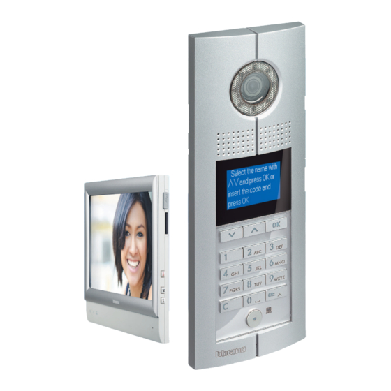
- Page 1 SYSteM tHe HigH peRFoRMaNce AUdio & Video door entrY SYSteM Project And inStAllAtion technicAl gUide the global specialist in door entrY SYSteM...
-
Page 3: General Features
technical guide GENERAL FEATURES GENERAL RULES FOR INSTALLATION WIRING DIAGRAMS AND VARIANTS CATALOGUE TECHNICAL SHEETS... -
Page 5: Table Of Contents
D45 System introduction . . . . . . . . . . . . . . . . . . . - Page 6 WIRING DIAGRAMS - VARIANTS Diagram 1 . . . . . . . . . . . . . . . . . . . . . . . . . . . . . . . . . . . . . . . . . . . 96 IU wired connection + alarm connection IU rear side connector Connection way for NC and NO contacts:...
- Page 7 BT-323005 BT-322030 BT-323007 BT-322031 BT-323008 BT-322032 BT-323009 BT-322033 BT-323010 BT-322020 BT-323011 BT-322021 BT-323012 BT-322001 BT-323013 BT-322002 BT-323015 BT-321070 BT-323016 BT-321071 BT-323021 BT-322052 BT-323017 BT-321061 BT-323018 BT-322050 BT-323019 BT-321011 BT-323020 BT-321060 BT-323023 BT-322040 BT-346858 BT-323001 BT-323002 BT-323022 D45 SyStem SuMMaRY WWW.LEGRAND.COM...
-
Page 10: World Presence & Technical Assistance
Software and ServiceS World presence & Technical assistance World presence web sites in order to find your nearest subsidiaries: For after sales technical assistance, please refer to the: www.bticino.com www.legrand.com... -
Page 11: Software
Free to download from the www.bticino.com website ExamplEs of YouDiagram softwarE scrEEnshots D45 SyStem GUIDE www.lEgranD.com... -
Page 12: Software And Services
Configuration the target devices (eP and interface, programming of d45 devices. tool, used by technicians to etc.) of the d45 system. The software is supplied within a download the configuration configuration tool (323020). -
Page 13: Glossary
The most commonly used cable sheath is PVC or LSZH (Low SmokeZero Halogen). D45 SyStEm GUIDE www.lEgranD.com... -
Page 14: D45 System Introduction
GENERAL FEATURES d45 System introduction d45 SYSTem is the best solution The use of uTP cables and rJ45 the functionalities typically required on the market for large projects connections for all the devices in large applications and brings to (high rise buildings, compounds of... - Page 15 FLOOR 1 FLOOR 1 To floor shunt To floor shunt floor 2 floor 2 Apartment 2 Apartment 3 Apartment 2 Apartment 3 Apartment 1 Apartment 4 Apartment 1 Apartment 4 To riser shunt Riser 3 D45 SyStEm GUIDE www.lEgranD.com...
-
Page 16: The Main Devices
GENERAL FEATURES The main devices enTranCe PaneL outdoor video pushbutton panel with camera. it can be used to call the video handsets and to activate the associated door lock. available in various look and installation models. DIgITAL COLOUR 10 CALL PUShbUTTONS 20 CALL PUShbUTTONS SMALL ENTRY FLOOR CALL... - Page 17 Scrolling EP activation Intercom — — Power supply 30 Vdc 30 Vdc 30 Vdc 30 Vdc 30 Vdc 30 Vdc Type of Wall mounted Wall mounted Wall mounted Wall mounted Wall mounted Wall mounted installation D45 SyStEm GUIDE www.lEgranD.com...
- Page 18 GENERAL FEATURES The main devices PorTer SWiTCHBoard This is a table-top device for multi- 323001 family systems, which provides access to the various apartment complex video door entry system functions: intercommunication among apartments, door lock management, light switching-on management, monitoring of cameras installed on common areas, and monitoring of apartment alarms.
-
Page 19: Entrance Panels
The video gains of each riser shunt district branch can be set separately. 323011 323013 D45 SyStEm GUIDE www.lEgranD.com... -
Page 20: Products List And Main Features
GENERAL FEATURES Products list and main features TYPE MODEL NAME CODE NUMbER FIXINg WAY DIMENSIONS (MM) CURRENT STANDbY AbSORPTION WORK Digital colour entrance panel 322010 Embedded 325 x 125 x 60,5 30 V / 110 mA 30 V / 290 mA Entrance panel with call address list 322011 Embedded... -
Page 21: System Composition
Apartment 2 Apartment 3 To floor shunt 323003 Apartment 1 Apartment 4 Floor shunt 323002 FLOOR 1 Connections with RJ45 – Cat 5E/6 cable Entrance panel Power supply 323005 D45 SyStEm GUIDE www.lEgranD.com... - Page 22 GENERAL FEATURES System composition SINGLE BUILDING WITH MORE RISERS For the installation of video systems splitter, 323007, and the floor shunts, with several branches, the 2-way video 323002, can be used. BRANCH 1 FLOOR 1 Apartment 2 Apartment 3 To floor shunt 323003 Apartment 1 Apartment 4...
- Page 23 BRANCH 2 FLOOR 2 Apartment 2 Apartment 3 To floor shunt 323003 Apartment 1 Apartment 4 Floor shunt 323002 Connections with RJ45 – Cat 5E/6 cable. Riser 2 D45 SyStEm GUIDE www.lEgranD.com...
- Page 24 GENERAL FEATURES System composition APARTMENT BLOCK WITH 1 MAIN ENTRANCE PANEL AND MORE SECONDARY ENTRANCE PANELS COMMON SYSTEM SECTION To next riser shunt Power supply 323005 Riser shunt 323003 Power supply 323005 Riser shunt 323003 Main entrance panel Power supply 323005 Power supply 323005 Riser shunt 323003...
- Page 25 BUILDING XX Connections with RJ45 Riser entrance panel Cat 5E/6 cable Floor shunt 323002 Riser XX BUILDING 2 Riser entrance panel Floor shunt 323002 Riser 2 BUILDING 1 Riser entrance panel Floor shunt 323002 Riser 1 D45 SyStEm GUIDE www.lEgranD.com...
- Page 26 GENERAL FEATURES System composition APARTMENT BLOCK WITH 1 MAIN ENTRANCE PANEL, MORE SECONDARY ENTRANCE PANELS AND SWITCHBOARD COMMON SYSTEM SECTION To next riser shunt Power supply 323005 Riser shunt 323003 Switchboard 323001 EP/ Switchboard shunt 323018 Power supply 323005 Power supply 323005 Riser shunt 323003 Main entrance panel Power supply 323005...
- Page 27 BUILDING XX Connections with RJ45 Riser entrance panel Cat 5E/6 cable Floor shunt 323002 Riser XX BUILDING 2 Riser entrance panel Floor shunt 323002 Riser 2 BUILDING 1 Riser entrance panel Floor shunt 323002 Riser 1 D45 SyStEm GUIDE www.lEgranD.com...
- Page 28 GENERAL FEATURES System composition VILLA COMPLEX WITH SWITCHBOARD To next floor shunt 323002 Riser entrance panel Riser shunt 323003 Villa shunt 323016 To next riser shunt 323003 Power supply 323005 Power supply 323005 Main entrance panel Switchboard 323001 EP/Switchboard shunt 323018 Connections with RJ45 –...
- Page 29 VILLA 1 Touch screen video internal unit Floor shunt 323002 Power supply 323010 Small EP 322020 VILLA 2 To next floor shunt 323002 Touch screen video internal unit Floor shunt 323002 Power supply 323010 Small EP 322020 D45 SyStEm GUIDE www.lEgranD.com...
-
Page 30: The Configuration
GENERAL FEATURES The configuration The configuration assigns a procedure. d45 system devices may „ configuration with SF2 software. „ progressive address to the device be configured in two ways: within the system, and programs it „ physical configuration (has priority „... -
Page 31: System Functions
(maximum duration of the momentarily busy. 323010. communication is 1 minute) with the entrance panel. Press again or replace the handset to stop the communication and switch the monitor off. D45 SyStEm GUIDE www.lEgranD.com... - Page 32 GENERAL FEATURES System functions Call Call Master Slave Pressing the door lock key will open the gate Each time the self-switching on key is pressed the images When a call is received, the master comes on, while the associated with the handset. displayed change.
- Page 33 „ When the memory is full, the „ terminate the inTerCom connection. oldest message is overwritten. D45 SyStEm GUIDE www.lEgranD.com...
- Page 34 GENERAL FEATURES System functions ALARM SOS ALARM FUNCTION ALARM FUNCTION ANTI-TAMPER FUNCTION This function gives the possibility This function that enables to have up When the alarm function is set, of sending a request for help to the to a maximum of 8 alarms (burglar a forced action on the internal switchboard by pressing a dedicated and technical alarms).
- Page 35 (max. 16). D45 SyStEm GUIDE www.lEgranD.com...
-
Page 38: General Rules For Installation
GENERAL RULES FOR INSTALLATION System layout General features home automation applications, it „ The layout of the conduits; The first step towards the installation „ is necessary that the layout of the „ The type of wiring; of a system is to design and ensure a „... -
Page 39: System Cable
System cable The D45 system only works correctly if CAT5E and CAT6 original cables are used. Twisted pairs offer good standard and differential immunity. The CAT5E and CAT6 cables must have a resistance value of 180 ohm/km (for every twisted pair). - Page 40 GENERAL RULES FOR INSTALLATION System cable caBles used cat. 5e u/utp caBleS Category 5E U/UTP unshielded cable with 24AWG (0.51 mm) solid copper conductors, polyolefin insulation, 4 pairs of twisted conductors with internal separator - in accordance with ISO/IEC 11801, and 2.0, EN 50173-1 and EIA/TIA 568 B2.10 standards - grey colour.
-
Page 41: Standard Rj45 Connections For Cat5 Cable
VIDEO + VIDEO - AUDIO + POWER + POWER - AUDIO - SCS- SCS+ The four pairs are identified with different colours and each pair carries a different type of signal (see Table 1). D45 SyStEm GUIDE WWW.LEGRAND.COM... -
Page 42: Rj45 Connections
GENERAL RULES FOR INSTALLATION RJ45 connections rJ45 wire Map and connection Method wire Map Colour White&orange Orange White&green Blue White&blue Green White&brown Brown SIGNAL Video+ Video- Audio+ Power+ Power– Audio- Data- Data+ Wire specification: CAT cable. 1. Tools for making and testing 2. - Page 43 EP/ lights indicate an open circuit or Backbone/main EP connection bad connection. to door lock and door lock connection to power supply. Type DC-loop: 2 x 1.0 mm² Resistance: 39.4 Ω / 1 km D45 SyStEm GUIDE WWW.LEGRAND.COM...
-
Page 44: Entrance Panels And Indoor Handsets Installation
GENERAL RULES FOR INSTALLATION Entrance panels and indoor handsets installation small ep/ep/main ep insTallaTion heighT handseT insTallaTion heighT Below is the recommended installation height for the When installing audio or video internal units, it is advisable entrance panel: to position the devices as indicated here. Note: to allow use by disabled people, the device must be installed at a height Note: to allow use by disabled people, the device must be installed at a height of 120-125 cm. -
Page 45: Entrance Panel Installation
Don’t install in hot or damp places Flush mounted box Flush mounted box Screw Screw Rack Rack Install the EP on the wall Install the EP on the door Note: the flush mounted box must be ordered separately. D45 SyStEm GUIDE WWW.LEGRAND.COM... -
Page 46: Small Entrance Panel Installation
GENERAL RULES FOR INSTALLATION Small entrance panel installation 322020 insTallaTion meThod 108 mm 30 mm > 1.00 m Don’t install in hot or damp places Size overview Installation height and position do noT insTall in hoT or damp places Installation method 1 Installation instruction: 1. -
Page 47: General Configuration Concept
The visitor calling the resident from The visitor calling the resident from the installation. The D45 system the unit/riser entrance panel has to the wall entry panel or the main let you use this codes to make calls... - Page 48 GENERAL RULES FOR INSTALLATION General configuration concept Flexible configuration: „ A PC can be used (but not default apartment functions are It is compulsory to configure: „ mandatory) to simplify the available. 1. Audio/video doorphone installation project (not needed handsets. For each handset, its F F I I address code must during the installation);...
- Page 49 4000 or less, Mode 1 configuration is possible, if the total number is over 4000, Mode 2 must be considered. characteristics for each configuration > 20 ≤ 4 Mode are described below: ≤20 > 4 > 20 > 4 D45 SyStEm GUIDE WWW.LEGRAND.COM...
- Page 50 GENERAL RULES FOR INSTALLATION General configuration concept For example: if the highest building *2*: Below is an example explaining the rules for system configuration (Mode 2): of a project has 25 floors, and the #ff for #ii for total riSer can SySteM configuration Mode 2 Be uSed? each riSer each floor...
-
Page 51: Ep Configuration Examples
EP is no. 2, main EP No need for configuration configuration should be as follows: C 2 This position can use the EP keyboard or the configuration tool for the configuration. N N #F #F #I #I D45 SyStEm GUIDE WWW.LEGRAND.COM... - Page 52 GENERAL RULES FOR INSTALLATION EP configuration examples Example (B): poSition Value for configurator reMarkS EP address, each riser has 25 floors, It is ok not to insert configurator 0 and each floor has 8 handsets. System configuration Mode 2 is used. the Switchboard directly connected It is ok not to insert configurator 0 to the main EP is no.
-
Page 53: Handset Configuration Examples
It is ok not to insert configurator 0 system configuration Mode is Mode 1, the handset configuration Because the default value of #II is 4, no configurator should be as follows: is needed #I #I 1 2 0 4 D45 SyStEm GUIDE WWW.LEGRAND.COM... - Page 54 GENERAL RULES FOR INSTALLATION Handset configuration examples Example (B): poSition Value reMarkS The number of handsets is 1206, each floor has 8 handsets. System It is ok not to insert configurator 0 configuration Mode 2 is used. The handset configuration should It is ok not to insert configurator 0 be as follows: #I #I...
-
Page 55: Accessory Configuration Examples
From 1 to 80 is Mode 1 or Mode 2, this parameter CF13 CF14 Riser EP quantity of riser is 0. If this configurator is set using CF15 CF16 Riser switchboard number From 1 to 15 D45 SyStEm GUIDE WWW.LEGRAND.COM... - Page 56 GENERAL RULES FOR INSTALLATION Accessory configuration examples Example (A): poSition Mode 1 Value for configurator reMarkS The number of riser shunts is 5, each 0 no config needed 0 no config needed riser has 20 floors, and each floor has 0 no config needed 4 handsets.
- Page 57 ASR: set how much current the Configurators position for power supply CF4 CF5 CF6 CF7 CF8 CF9 CF10CF11 TYP ASR M TYP ASR M D45 SyStEm GUIDE WWW.LEGRAND.COM...
- Page 58 GENERAL RULES FOR INSTALLATION Accessory configuration examples TYP: configuration position for the power Supply ManageMent function SMart power function power supply function (√means that × × this function is available, X means √ √ that this function is not available). ×...
- Page 59 For Mode 1 and Mode 2, CF10 and CF11 should be as follows: do not apply CF11 CF11 CF12 Type CF13 CF14 CF15 CF4 CF5 CF6 CF7 CF8 CF9 CF10CF11 TYP ASR M TYP ASR M D45 SyStEm GUIDE WWW.LEGRAND.COM...
- Page 60 GENERAL RULES FOR INSTALLATION Accessory configuration examples Example (B): Value for poSition Mode 1 reMarkS configurator This riser has 20 floors, and each floor has 5 handsets. This power supply manages 1-2 floors. If necessary enable the smart power FF Min function and the power management FF Min function, the power supply address...
- Page 61 0 mA. The CF11 CF11 system used Mode 3 configuration. Type CF12 The power supply configuration CF13 should be as follows: CF14 CF15 CF4 CF5 CF6 CF7 CF8 CF9 CF10CF11 TYP ASR M TYP ASR M D45 SyStEm GUIDE WWW.LEGRAND.COM...
- Page 62 GENERAL RULES FOR INSTALLATION Accessory configuration examples 323005 - power supply configuraTion choosing The sysTem power soluTion „ Solution 1: PWS 323005 will be „ „ Solution 2: PWS 323005 will be Note: when the system includes Small EP, solution „...
-
Page 63: Lock Type And Distance Limits
Lock type and distance limits recommended rJ45 connecTor The actual working environment may We recommend that Legrand/ The types of door locks below be damp or hot, which can cause Ortronics connectors are used are also recommended inferior RJ45 connectors to rust. - Page 64 GENERAL RULES FOR INSTALLATION Lock type and distance limits For this kind of door lock, an additional power supply must be used. The connection method is shown below. EP/WEP L- -L+ Door lock release LOCK 323015 Power Power supply Max distance ≤ 250 m Max distance ≤...
-
Page 65: Power Supply Installation Rules
Never separate from riser to BUS! smart function, the PWS will be set as auxiliary power supply; otherwise, the auxiliary power supply will be used. D45 SyStEm GUIDE WWW.LEGRAND.COM... - Page 66 GENERAL RULES FOR INSTALLATION Power supply installation rules legend One 323005 is needed in the main network area One 323005 is needed in the green area of the unit One 323005 is needed in the blue area connected to - 323019 UnIT 2 handset handset...
- Page 67 323005 (Set 323005 as system power supply) Difference for each connector line power Video audio data colour connection connection connection connection √ √ √ √ √ Connector for 323005 √ √ √ √ √ √ √ D45 SyStEm GUIDE WWW.LEGRAND.COM...
- Page 68 GENERAL RULES FOR INSTALLATION Power supply installation rules 1) When there is no riser shunt in the system, the system power supply should Impedance switch be connected and set as following drawing: 323002 323002 POWER B C A 323005 2) When there is riser shunt in the system, the system power supply should be connected and set as following drawing: Power supply 323005...
- Page 69 BUS system auxiliary power supply. Connection should be as per the following drawing: To Riser to next floor shunt Switchboard handset handset Backbone 323002 323001 handset handset To Riser from previous 323010 floor shunt D C A 323005 D45 SyStEm GUIDE WWW.LEGRAND.COM...
-
Page 70: Power Supply Check And Calculation
GENERAL RULES FOR INSTALLATION Power supply check and calculation Before proceeding to the system installation, it is necessary to check the power supply of the whole system: 1. Check that the power supplies 2. Check that the distance (in meters 3. - Page 71 DC12 V/1 A., release time 100 afford other 40 handsets except ms or less. The door lock does not EP and riser shunt according need power during. D45 SyStEm GUIDE WWW.LEGRAND.COM...
- Page 72 GENERAL RULES FOR INSTALLATION Power supply check and calculation Maximum distance between EP or Case 1, case 2, case 3, case 4, case 7, Notes: handset and power supply. case 8, case 9 are for 323005(PW1) 1. The current can also be affected by the distance. In the riser, the quantity of devices and 323010(aPW1).
- Page 73 Remark: In table 4, table 5 and table 6 , in case 4, case 5, case 6, case 10, case 11 and case 12, the quantity of handsets is only for 323005. If using 323010, Please refer to table 7; D45 SyStEm GUIDE...
- Page 74 GENERAL RULES FOR INSTALLATION Power supply check and calculation Table 7: 323010 application on case 4, case 5, case 6, case 10, case 11 and case 12 handSet How many apartments on every floor Case 4 Case 5 Case 6 Case 10 Case 11 Case 12...
-
Page 75: Maximum System Limits
B/W signal, please take into account the actual image 700 – 1000 m when setting the data. 1 2 3 4 1000 –1500 m ON B/W signal 1 2 3 4 1500 – 2000 m ON D45 SyStEm GUIDE WWW.LEGRAND.COM... - Page 76 GENERAL RULES FOR INSTALLATION Maximum system limits Example for distance limits: cascade insTallaTion limiTs of video signal After being transmitted by multilevel If any of the following devices is cascade (insert video amplifier, video passed by a video signal in the splitter etc in transmission channel), the system, the cascade level should video signal will have distortion and...
- Page 77 50 m Internal unit - Floor shunt Internal unit - Power suplly of Floor shunt Max. distance line C Max. distance line C 70 m 70 m Power supply - Entrance panel Power supply - Entrance panel D45 SyStEm GUIDE WWW.LEGRAND.COM...
- Page 78 GENERAL RULES FOR INSTALLATION colour sysTem - mulTiple risers Furthest Max. distance line A internal unit 1 Km Furthest internal unit - Entrance panel Max. distance line B 50 m Furthest internal unit - Riser main Power supply Max. distance line C 50 m Internal unit - Floor shunt Max.
- Page 79 Internal unit - Power supply of Flor shunt Max. distance line C 70 m Entrance panel - Power supply Floor shunt 323002 Additional power supply of floor shunt 323010 Riser shunt 323003 Riser main power suplply 323005 Main power supply 323005 Entrance panel D45 SyStEm GUIDE WWW.LEGRAND.COM...
-
Page 80: Troubleshooting
GENERAL RULES FOR INSTALLATION Troubleshooting 1. The indicators flash when the 5. How to make sure that the riser 7. The entrance panel fails to call a handset is called, but there installation is correct. certain handset. Once installing a handset, first is no ring. - Page 81 If the handset starts the doorbell immediately: function, it will automatically This is the result of a short-circuit on the Small EP. Please eliminate the problem and then reconnect. 18. The secondary EP can call the D45 SyStEm GUIDE WWW.LEGRAND.COM...
-
Page 84: Wiring Diagrams
WIRING DIAGRAMS Diagram 1 Handsets riser connection witH floor sHunt 323002 321070 321070 0 2 0 2 0 2 0 3 F F I I #I #I F F I I #I #I 323002 321070 321070 0 2 0 1 0 2 0 4 F F I I #I #I F F I I #I #I... - Page 85 7" Touch screen internal unit Electric door lock 12V - 4A impulsive Set internal IMPEDANCE SWITCH to ON. Door lock release pushbutton Auxialiary PWS must be used in relation with the system distance extension - see specific section. D45 SyStEm GUIDE WWW.LEGRAND.COM...
-
Page 86: Diagram 2
WIRING DIAGRAMS Diagram 2 riser witH 2 brancHes video splitter 323007 To next floor shunt 323002 321070 321070 0 1 0 2 0 8 0 1 0 3 F F I I #I #I F F I I #I #I 323002 321070 321070... - Page 87 To install alternative Entrance panel, refer to wiring variant section. 321070 7" Touch screen internal unit Device configuration by SF2 software. Electric door lock 12V - 4A impulsive Door lock release pushbutton Set internal IMPEDANCE SWITCH to ON. D45 SyStEm GUIDE WWW.LEGRAND.COM...
-
Page 88: Diagram 3
WIRING DIAGRAMS Diagram 3 backbone system witH 1 main entrance panel WARNINGS: „ „ Configure and insert the jumpers with the system SWITCHED OFF. Also every time the configuration is modified the pws must be switched OFF and ON again, waiting about 1 minute. - Page 89 0 4 F F I I #I #I F F I I #I #I 323003 323003 CF4= 2 CF4= 3 To next riser shunt 323003 323005 323005 + – – + + – – + D45 SyStEm GUIDE WWW.LEGRAND.COM...
-
Page 90: Diagram 4
WIRING DIAGRAMS Diagram 4 backbone system witH 1 main entrance panel and porter switcHboard 323001 WARNINGS: „ „ Configure and insert the jumpers with the system ITEM DEscrIPTION SWITCHED OFF. Also every time the configuration is Digital call entrance panel 322011 modified the pws must be switched OFF and ON again, waiting about 1 minute. - Page 91 F F I I #I #I F F I I #I #I CF4= 2 CF4= 3 C= 1 C= 1 323003 323003 To next riser shunt 323002 323005 323005 + – – + + – – + D45 SyStEm GUIDE WWW.LEGRAND.COM...
-
Page 92: Diagram 5
WIRING DIAGRAMS Diagram 5 system witH district generator 323013 RISER BLOCK 2 323003 323003 To next riser shunt 323003 323005 323005 + – – + + – – + RISER BLOCK 1 0 1 0 EPS EPS 323013 323001 323005 323010 + –... - Page 93 Digital call entrance panel 323010 Auxiliary power supply + – – + 323005 Main power supply 303003 Riser shunt 323013 District generator L – UNLOCK 323001 Porter switchboard Electric door lock 12V - 4A impulsive Door lock release pushbutton D45 SyStEm GUIDE WWW.LEGRAND.COM...
-
Page 94: Diagram 6
WIRING DIAGRAMS Diagram 6 riser witH lift control interface 323017 Example Building with 14 floor: 2 to 14 are PRIVATE floors and every floor has 4 apartments. Floor 1 is a PUBLIC floor with one entrance panel. Delay time set a 10 sec. (CF7= 1). This system needs n° 2 lift control interfaces. 323002 OUTPUT8 323017... - Page 95 Set internal IMPEDANCE SWITCH to ON. 323017 Lift control interface Auxialiary PWS must be used in relation with the system Electric door lock 12V - 4A impulsive distance extension - see specific section. Door lock release pushbutton D45 SyStEm GUIDE WWW.LEGRAND.COM...
-
Page 96: Diagram 7
WIRING DIAGRAMS Diagram 7 town villas system witH villa sHunt 323016 mx 200 m 323016 DIsTANcE WARNINGS: 200 m „ „ Configure and insert the jumpers with the system SWITCHED OFF. Also every time the configuration is 200 - 400 m sIGNAL modified the pws must be switched OFF and ON again, waiting about 1 minute. - Page 97 323002 321070 F F I I #I #I 322020 323010 R1 R2 R3 R4 + – – + 323002 321070 F F I I #I #I 322020 323010 R1 R2 R3 R4 + – – + D45 SyStEm GUIDE WWW.LEGRAND.COM...
-
Page 98: Diagram 8
WIRING DIAGRAMS Diagram 8 system witH d45 interface and fiber optic connection WARNINGS: „ „ Configure and insert the jumpers with the system ITEM DEscrIPTION SWITCHED OFF. Also every time the configuration is modified the pws must be switched OFF and ON again, 322011 Digital call entrance panel waiting about 1 minute. - Page 99 0 1 0 3 F F I I #I #I F F I I #I #I 323002 321070 321070 0 1 0 1 0 1 0 4 F F I I #I #I F F I I #I #I D45 SyStEm GUIDE WWW.LEGRAND.COM...
-
Page 100: Diagram 9
WIRING DIAGRAMS Diagram 9 system witH d45 interface and software switcHboard WARNINGS: ITEM DEscrIPTION „ „ Configure and insert the jumpers with the system 322011 Digital call entrance panel SWITCHED OFF. Also every time the configuration is modified the pws must be switched OFF and ON again, 323011 D45/IP interface waiting about 1 minute. - Page 101 Full Link System + – – + 323011 L – UNLOCK SYSTEM2 V OUT GAIN SYSTEM1 322011 323011 323005 Speed Full Link System + – – + 323011 SYSTEM2 V OUT GAIN SYSTEM1 L – UNLOCK D45 SyStEm GUIDE WWW.LEGRAND.COM...
-
Page 104: Wiring Diagrams - Variants
WIRING DIAGRAMS - VARIANTS Diagram 1 iu wired connection + alarm connection ALARM SENSORS SENSOR SENSOR GND 12V GND 12V Normally a standard 0.5 mm cable can be used (depending on sensor type and installation distance) For video signals a standard cable can be used. For data signals use a 0.5 mm cable (in accordance with installation distances) -
Page 105: Connection Way For Nc And No Contacts
10 K 10 K 10 K 10 K 10 K 10 K 10 K 10 K 10 K 10 K 10 K 10 K 10 K 10 K 10 K 10 K 10 K 10 K 10 K GUIDE WWW.LEGRAND.COM... -
Page 106: Diagram 2
WIRING DIAGRAMS - VARIANTS Diagram 2 basic apartment interface connection The indoor units must have the same address FFII#I#I. handset handset 323008 handset POWER – + Remarks: 323002 when the total power consumption for all handsets connected to 323008 exceeds the limit, an auxiliary power supply (323010) is required. -
Page 107: Diagram 3
N= 2 SYSTEM 344602 To Handset To IU 2 To IU 3 230 Vac BUS SCS N= 1 323002 346858 346030 346858 BTICINO 2 SCS A-V WIRE FFII:0104 SYSTEM POWER – + Sub System OUT Sub System IN GUIDE WWW.LEGRAND.COM... -
Page 108: Diagram 4
WIRING DIAGRAMS - VARIANTS Diagram 4 apartment interface connection Remarks: if powered through the unit bus system, only one indoor unit can be set as the master indoor unit. 323009 323015 322020 To configure the interface with address FFII#I#I To HANDSET 2 To HANDSET 3 POWER –... -
Page 109: Diagram 5
To Riser shunt or Power supply NOTE: each entrance panel can be replaced with 323004, to obtain up to 25 entrance panels. 323003 323004 Entrance Panel Entrance Panel 1 2 3 4 POWER – + Entrance Panel Entrance Panel Entrance Panel GUIDE WWW.LEGRAND.COM... -
Page 110: Diagram 6
WIRING DIAGRAMS - VARIANTS Diagram 6 wiring diagrams - door lock relay connection 322010 322011 346250 NC NO S- S+ L+ L- 8A cosϕ = 1 24 Vac/24 Vdc N.B.: Cable size 1 mm and max distance 2 meters 4A cosϕ = 0.7 24 Vac 3A cosϕ... -
Page 111: Diagram 8
BACK BONE Diagram 9 power supply connection for switcHboard WARNINGS: Advanced configuration by software MHSUITE. 323001 323010 Blue Yellow and green + – – + Brown AC input This wire must be connected to earth ground BACK BONE GUIDE WWW.LEGRAND.COM... -
Page 112: Connection Of Entrance Hall Pushbutton To The Entrance Panel
BACK BONE WIRING DIAGRAMS - VARIANTS Diagram 10 connection of entrance Hall pusHbutton to tHe entrance panel 322010 322011 UNLOCK +12V UNLOCK +12V Diagram 11 floor call connection INTERNAL UNIT Enable the service with the code: #686868#16#1 “LONG TONE”. Diagram 12 back-up battery connection 323005 / 323010 24Vdc BATTERY... -
Page 113: In/Out Connection
Diagram 13 in/out connection 321070 x x x x F F I I #I #I 323022 321070 0 1 0 1 F F I I #I #I 323022 322030 L – UNLOCK 323005 + – – + GUIDE WWW.LEGRAND.COM... -
Page 114: Single Family System With More Then 1 Entry Panel
WIRING DIAGRAMS - VARIANTS Diagram 14 single family system witH more tHen 1 entry panel 321070 323010 323023 CF1= OFF 0 1 0 1 CF2= OFF CF3= OFF F F I I #I #I + – – + CF4= ON 322020 322020 323015... - Page 115 CF1= OFF 0 1 0 1 CF2= OFF F F I I #I #I CF3= ON + – – + CF4= OFF 322020 322020 322020 323015 323015 323015 Connections with RJ45 – Cat 5E/6 cable. 4 Wires 2 Wires GUIDE WWW.LEGRAND.COM...
-
Page 118: Bt-322021
D45 System entrance panels 322010 322030 322031 322032 322033 322020 322021 322011 Digital calls colour entrance panels Additional pushbutton module Pack Cat.Nos Pack Cat.Nos Zamak digital call street panel with keyboard, Additional Zamak pushbutton panel with LCD display and colour camera... -
Page 119: Bt-322052
D45 System internal units 321070 322050 321061 321071 321011 322052 321060 322040 323001 Touch screen hands-free internal units Hands-free colour internal units Pack Cat.Nos Pack Cat.Nos Complete door entry functions with alarm For standard video door entry functions plus managements... - Page 120 D45 System system accessories 323002 323003 323005 323009 System accessories System accessories (continued) Pack Cat.Nos Pack Cat.Nos Floor shunt Basic apartment interface BT-323002 BT-323008 This is used to convert video signals on the BUS Device must be used in apartments with 2 or 3...
-
Page 121: Bt-323012
IP management switchboard software Lift control interface BT-323012 BT-323017 Integrated IP management software provides the For integrating the D45 system with the elevator communication for calls between internal units system and the switchboard Possibility to manage the elevator directly from... -
Page 124: Technical Sheets
Collection diagram, if applicable. „ „ item code. BTicino SpA Viale Borri, 231 21100 Varese - Italy www.bticino.com d45 SYSteM tHe HigH peRFoRMaNce AUdio & Video door entrY SYSteM Technical sheets can be viewed and downloaded by accessing the on-line www.bticino.com... - Page 125 321070 Front & side views Description D45 System 7” touch screen video internal unit. Complete door entry functions with alarm managements. International standard SOS pushbutton, intercom function, programming device touch screen functions. Digital photo frame and camera functions. Device drawing Direct call to switchboard function.
- Page 126 321010 Description Front view D45 System indoor handsfree video handset with 5.6” analogue LCD backlit display. Complete door entry functions with alarms management. International standard SOS pushbutton and keyboard for intercom function and programming device. Direct call to switchboard function. 12 ring tones selectable for different call types. Surge protection.
- Page 127 Colour 5.6” handsfree indoor handset 321010 Configuration Rear view Indoor handset must be configured for following parameters: I #I #I FF : Floor number II : Apartment number #II : Maximum apartments quantity per floor in a riser Two different configuration modes available for whole system: configuration MODE 1 and configuration MODE 2.
-
Page 128: The Technical Sheets
Colour 5.6” handsfree indoor handset 321010 Two different device configuration ways available: WAY 1) Configuration settings by device keyboard WAY 2) Configuration settings by inserting phisical configurators Configuration settings by device keyboard - WAY 1: When the handset is in standby and all zone alarms are disabled, press “#”, then enter be heard, and the unit will switch to installation setup status. - Page 129 Colour 5.6” handsfree indoor handset 321010 Configuration settings by device keyboard - WAY 1: INSTAllATION SETTINgS OPErATION lIST TABlE SETUP OPErATION CODE AND NExT MEANINg AND INFOrMATION FOr ThE OPErATION rEMArk lIghT STATUS OPErATION Set infrared sensor infrared sensor for alarm zone 5: LED 5 on, 1 long tone Message light is off.
- Page 130 Colour 5.6” handsfree indoor handset 321010 Configuration settings by inserting phisical configurators - WAY 2: Master and Slave settings Slave #I #I Master FF : Floor number II : Apartment number #II : Maximum apartments quantity per floor in a riser Configuration examples: Example (A): The number of handsets is 1204, each floor has 4 handsets, the system configuration...
- Page 131 Colour 5.6” handsfree indoor handset 321010 +12 V +12 V Wiring diagram - alarm sensors connections +12 V +12 V +12 V sensor 8 sensor 8 sensor 7 sensor 7 sensor 8 sensor 8 sensor 8 sensor 6 sensor 6 sensor 7 sensor 7 sensor 7...
- Page 132 Colour 5.6” handsfree indoor handset 321010 Connection way for NC and NO contacts AlArM ArEA SENSOr TYPE SENSOr TYPE REMARK Can use short key to sensor active or idle SENSOR 1 INFRARED SENSOR THEFT ALARM SENSOR 2 DOOR SENSOR Can’t use short key to let sensor idle SENSOR 3 SMOKE SENSOR FIRE ALARM...
- Page 133 321011 Description Front view D45 System colour handsfree internal unit with 3.5” LCD backlit display. Complete door entry functions with alarms management. International standard SOS pushbutton and keyboard for intercom function and programming device. Direct call to switchboard function. 12 ring tones selectable for different call types. Surge protection. Wall mount installation.
- Page 134 3.5 “ Colour handsfree internal unit 321011 Configuration Rear view Device MUST be configured for following parameters: I #I #I FF : Floor number II : Apartment number #II : Maximum apartments quantity per floor in a riser Two different configuration modes available for whole system: configuration MODE 1 and configuration MODE 2.
- Page 135 3.5 “ Colour handsfree internal unit 321011 Configuration Two different device configuration ways available: Configuration settings by device keyboard - WAY 1 Configuration settings by inserting phisical configurators - WAY 2 Configuration settings by device keyboard - WAY 1: When the handset is in standby and all zone alarms are disabled, press “#”, then enter the fixed installer password 686868, and press “#”...
- Page 136 3.5 “ Colour handsfree internal unit 321011 Configuration FROM PREVIOUS PAGE → Configuration settings by device keyboard - WAY 1: INSTAllATION SETTINgS OPErATION lIST TABlE SETUP OPErATION CODE AND NExT MEANINg AND INFOrMATION FOr ThE OPErATION rEMArk lIghT STATUS OPErATION Set infrared sensor infrared sensor for alarm zone 5: LED 5 on, 1 long tone Message light is off.
- Page 137 3.5 “ Colour handsfree internal unit 321011 Configuration Configuration settings by device keyboard - WAY 2: MASTEr and SlAvE settings Slave #I #I Master FF: Floor number II: Apartment number #II: Maximum apartments quantity per floor in a riser Configuration examples: Example (A): The number of handsets is 1204, each floor has 4 handsets, the system configuration mode is MODE 1, the handset configuration should be as follows:...
- Page 138 3.5 “ Colour handsfree internal unit 321011 +12 V +12 V +12 V +12 V Wiring diagram - alarm sensors connections sensor 8 sensor 8 sensor 7 sensor 7 sensor 8 sensor 8 +12 V sensor 6 sensor 6 sensor 7 sensor 7 sensor 5 sensor 5...
- Page 139 3.5 “ Colour handsfree internal unit 321011 NC & NO alarm sensors connection table AlArM ArEA SENSOr TYPE SENSOr TYPE REMARK Can use short key to sensor active or idle SENSOR 1 INFRARED SENSOR THEFT ALARM SENSOR 2 DOOR SENSOR Can’t use short key to let sensor idle SENSOR 3 SMOKE SENSOR...
- Page 140 321060 Description Front view D45 System entry level colour handsfree internal unit with 3.5” LCD backlit display. Complete door entry functions. Direct call to switchboard function. 12 ring tones selectable for different call types. Surge protection. Wall mount installation. Technical data...
- Page 141 3.5 “ Colour handsfree internal unit 321060 Configuration Rear view Device MUST be configured for following parameters: I #I #I FF : Floor number II : Apartment number #II : Maximum apartments quantity per floor in a riser Two different configuration modes available for whole system: Legend configuration MODE 1 and configuration MODE 2.
- Page 142 3.5 “ Colour handsfree internal unit 321060 Configuration Two different device configuration ways available: Configuration settings by device keyboard - WAY 1 Configuration settings by inserting phisical configurators - WAY 2 Configuration settings by device keyboard - WAY 1: When the handset is in standby mode, press and mantain the door lock key until a long tone is heard. With information & connection status LEDs OFF you are in settings mode. Then within 10 seconds, press and mantain the call to the switchboard key until a long tone is heard to enter into the initial installation settings (you can set parameters without selecting submenus).
- Page 143 3.5 “ Colour handsfree internal unit 321060 Configuration FROM PREVIOUS PAGE → Configuration settings by device keyboard - WAY 1: SET ThE ExTErNAl SOS CONTACT TYPE FUNCTION OPErATION Select the setting submenu of the external SOS contact At initial settings status, short-press on the call to the switchboard key five times and enter into the setting submenu for the external SOS type to set the submenu contact type.
- Page 144 3.5 “ Colour handsfree internal unit 321060 Configuration Configuration settings by device keyboard - WAY 2: MASTEr and SlAvE settings Slave Master I #I #I FF : Floor number II : Apartment number #II : Maximum apartments quantity per floor in a riser Configuration examples : Example (A) : The number of handsets is 1204, each floor has 4 handsets, the system configuration...
- Page 145 321070 Front & side views Description D45 System 7” touch screen video internal unit. Complete door entry functions with alarm managements. International standard SOS pushbutton, intercom function, programming device touch screen functions. Digital photo frame and camera functions. Direct call to switchboard function. 6 different default selectable ringtones (can be changed with your favourite music).
- Page 146 7” touch screen handsfree internal unit 321070 Configuration Indoor handset must be configured for following parameters: FF : Floor number II : Apartment number I #I #I #II : Maximum apartments quantity per floor in a riser Two different configuration modes available for whole system: configuration MODE 1 and configuration MODE 2.
- Page 147 7” touch screen handsfree internal unit 321070 Configuration Room number iU Type Click on the white circle to select “With apartment interface 323009” or “Without Click on the white circle to select “Master” or “Slave” IU. When one apartment install apartment interface 323009”.
- Page 148 7” touch screen handsfree internal unit 321070 Configuration Configuration setting by inserting phisical configurators - WAY 2 : Example (A): Example (B): The number of handsets is 1204, each floor has 4 handsets, the system configuration The number of handsets is 1206, each floor has 8 handsets. System configuration mode mode is Mode 1, the handset configuration should be as follows 2 is used.
- Page 149 7” touch screen handsfree internal unit 321070 LED indicators status of the internal unit anti disturb mode Blue Common mode status leD Pink outside mode Quick flash Being called, no answer slow flash Talking no new message information leD Blue Quick flash new message Unguarded...
- Page 150 321071 Front & side views Description D45 System 10” touch screen video internal unit. Complete door entry functions with alarm managements. International standard SOS pushbutton, intercom function, programming device touch screen functions. Digital photo frame and camera functions. Direct call to switchboard function. 6 different default selectable ringtones (can be changed with your favourite music).
- Page 151 10” touch screen handsfree internal unit 321071 Configuration Indoor handset must be configured for following parameters: FF : Floor number II : Apartment number I #I #I #II : Maximum apartments quantity per floor in a riser Two different configuration modes available for whole system: configuration MODE 1 and configuration MODE 2.
- Page 152 10” touch screen handsfree internal unit 321071 Configuration Room number iU Type Click on the white circle to select “With apartment interface 323009” or “Without Click on the white circle to select “Master” or “Slave” IU. When one apartment install apartment interface 323009”.
- Page 153 10” touch screen handsfree internal unit 321071 Configuration Configuration setting by inserting phisical configurators - WAY 2 : Example (A): Example (B): The number of handsets is 1204, each floor has 4 handsets, the system configuration The number of handsets is 1206, each floor has 8 handsets. System configuration mode mode is Mode 1, the handset configuration should be as follows 2 is used.
- Page 154 10” touch screen handsfree internal unit 321071 LED indicators status of the internal unit anti disturb mode Blue Common mode status leD Pink outside mode Quick flash Being called, no answer slow flash Talking no new message information leD Blue Quick flash new message Unguarded...
- Page 155 Description Front view D45 System entrance panel with colour camera and backlighted alphanumeric keyboard equipped with : pushbutton to direct calls to the porter switchboard; door lock opening with a numeric code to residents. Possibility to send an alarm message to the switchboard when opening over 2 minutes of the associated lock or when trying to remove the device.
- Page 156 Digital colour entrance panel 322010 Configuration Rear view Entrance panel must be configured for following parameters: NN : Entrance panel number # FF : Floor quantity in a riser N N #F #F #I #I # II : Maximum apartment quantity per floor in a riser Two different configuration modes available for whole system : configuration MODE 1 and configuration MODE 2.
- Page 157 Digital colour entrance panel 322010 Three different device configuration ways available: WAY 1) Configuration settings by device keyboard WAY 2) Configuration settings by inserting phisical configurators WAY 3) Configuration by using SF2 Software and PC connection Configuration settings by device keyboard - WAY 1: Press the # key for about 5 seconds.
- Page 158 Digital colour entrance panel 322010 Mode 5 and Mode 6: When the building number plus unit number (building number and Select 5 to complete entrance panel configuration parameters setting. unit number are coded separately) plus floor number plus room number is not above 9 As per the prompt on the display interface, we can set the address of the entrance panel, digits, one of them can be selected.
- Page 159 Digital colour entrance panel 322010 Configuration settings by inserting phisical configurators - WAY 2: Configuration examples: Physical connection for the configurators to their sockets Example (A): EP address is 5, each riser has 20 floors, and each floor has 4 handset: system configura- tion mode 1 is used.
- Page 160 Digital colour entrance panel 322010 Configuration video gain setting The entrance panel has two video compensation gears. By setting different V-GAIN Configuration by using SF2 Software and PC connection - WAY 3 : gears, we can let the video signal output adapt to different transmission distance. See This is the enhanced way to download the device configuration to entrance panel followings: previously created by using SF2 configuration software and a personal computer.
- Page 161 Front view Description D45 System entrance panel with colour camera and backlighted alphanumeric keyboard equipped with pushbutton to direct calls to the porter switchboard. Possibility to send an alarm message to the switchboard when opening over two minutes of the associated lock or when trying to remove the device.
- Page 162 Digital colour entrance panel 322011 with addresses list Flush mounting box - dimensional data Rear view Legend A (mm) B (mm) C (mm) 1. NN RRRR: configurators housing 2. ISP: entrance panel software upgrade connector 3. SPK: loudspeaker volume adjust 4.
- Page 163 Digital colour entrance panel 322011 with addresses list Configuration & Settings Entrance panel must be configured for the following parameters: : Entrance panel number N N R R R R RRRR : NOT USED Two different device configuration ways available: WAY 1) Configuration settings by device keyboard WAY 2) Configuration by using SF2 Software and PC connection Configuration settings by device keyboard - WAY 1:...
- Page 164 Digital colour entrance panel 322011 with addresses list Configuration & Settings Changing the PASSWORD - if the password has been forgotten , it is possible to change it in this way : press the RESET pushbutton on the rear side of the device for about 6 seconds. Password will be recovered to default (1 2 3 4).
- Page 165 Digital colour entrance panel 322011 with addresses list Configuration & Settings HOME PAGE - this menu function allows you to enter a customized welcome message or any other general message. The message can fill a maximum of three text rows (15 characters max.) - Template. Is possible to set the display time of the message on the screen (5, 10 or 15 seconds) - Timeout.
- Page 166 Digital colour entrance panel 322011 with addresses list Configuration & Settings ADDRESS BOOK - This menu is used to to enter various residents data (including call codes and door lock release codes) as well as performing any other function described below : cONFIguRAtION cONFIguRAtION Panel settings...
- Page 167 Digital colour entrance panel 322011 with addresses list Configuration & Settings Contact setting - call codes can be set with a lenght from 1 to 8 digits. Door lock codes can be set with a lenght from 4 to 9 digits. ADDRESS BOOK ADDRESS BOOK contact setting...
- Page 168 Digital colour entrance panel 322011 with addresses list Configuration & Settings Delete contact - this function gives you the possibility to delete the selected contact. ADDRESS BOOK Aaaaa Bbbbb New contact ccccc modify contact Ddddd Delete contact Select the contact to delete with than press DEL tHIS cONtAct confirm...
- Page 169 Digital colour entrance panel 322011 with addresses list Configuration & Settings Speaker module settings - this configuration can be performed only with the module NOT phisically configured (NO configurators inserted). ScS SEttINgS P – Panel number t – Lock time Switchboard P-Panel number: SCS address of the entrance panel...
- Page 170 Digital colour entrance panel 322011 with addresses list Configuration Video gain settings Configuration by using SF2 Software and PC connection - WAY 2 : The entrance panel has a double DIP SWITCH for the video compensation setting. By setting different DIP V-GAIN, it is possible to adapt the video signal to different This is the enhanced way to download the device configuration to entrance panel transmission distances - refer as follows : previously created by using SF2 configuration software and a personal computer.
- Page 171 Targa / Nameplate module 322012 Description D45 System zamak nameplate /targa module to be installed side by side to the digital call entrance panel 322012 to insert the list of residents or customised messages. Easy insertion / replacement of nameplates.
- Page 172 Description Front view D45 System aluminium alloy small colour camera entrance panel to be installed on the front of the apartment door. Can call indoor handsets and direct conversation. Analogue 4 wires connections to D45 system internal unit. Surface mounting installation. NO configuration required.
- Page 173 322030 Description Front view D45 System entrance panel (EP) with colour camera and 10 backlighted call pushbuttons with possibility to direct call to the porter switchboard. Possibility to send an alarm message to the switchboard when opening over 2 minutes of the associated lock or when trying to remove the device.
- Page 174 Call mode D45 system have two call modalities, one is room number mode, another is SCS ad- dress mode (direct call mode). In room number mode, internal unit can be set accord- ing to the room number; visitor type room number in entrance panel to call resident.
- Page 175 10 Pushbuttons colour video entrance panel 322030 Configuration Setting of door lock status: video gain setting device in stand by status - press and mantain for about 3 seconds the key located The entrance panel has two video compensation gears, we can let the video signal on the back of the entrance panel.
- Page 176 10 Pushbuttons colour video entrance panel 322030 Configuration Configuration settings by inserting physical resistor configuration - WAY 1: SCS address mode (direct call mode) First, jumper select (CF) entering setting status, than jumper select (SCS) entering SCS Factory default is room number, see pushbutton corresponding room number as follows: address mode.
- Page 177 322031 Description Front view D45 System entrance panel (EP) with colour camera and 20 backlighted call pushbuttons with possibility to direct call to the porter switchboard. Possibility to send an alarm message to the switchboard when opening over 2 minutes of the associated lock or when trying to remove the device.
- Page 178 Call mode D45 system have two call modalities, one is room number mode, another is SCS ad- dress mode (direct call mode). In room number mode, internal unit can be set accord- ing to the room number; visitor type room number in entrance panel to call resident.
- Page 179 20 Pushbuttons colour video entrance panel 322031 Configuration SCS address mode (direct call mode) Configuration settings by inserting physical resistor configuration - WAY 1: First, jumper select (CF) entering setting status, than jumper select (SCS) entering SCS address mode. Insert configurators, last press the pushbutton which you want to set in Factory default is room number, see pushbutton corresponding room number as follows: the front of panel until a long tone be heard.
- Page 180 20 Pushbuttons colour video entrance panel 322031 Configuration Setting of door lock status: video gain setting device in stand by status - press and mantain for about 3 seconds the key located The entrance panel has two video compensation gears, we can let the video signal on the back of the entrance panel.
- Page 181 322032 Description Front view D45 System additional 16 pushbuttons panel. Equipped with 16 backlighted call pushbuttons and possibility to direct call to the porter switchboard. Setup key functions via programming,phisical configurators insertion or through the dedicated software supplied with the product. Flush mounting installation with dedicated box (supplied with the product).
- Page 182 → Call mode → D45 system have two call modalities, one is room number mode, another is SCS address → mode (direct call mode). In room number mode, internal unit can be set according to →...
- Page 183 Additional 16 call pushbuttons panel 322032 Configuration Setting of rOOM NUMBEr or SCS ADDrESS for each pushbutton Configuration by using SF2 Software and PC connection- WAY 2 : This is the enhanced way to download the device configuration to additional pushbut- room mode number tons panel previously created by using SF2 configuration software and a personal First select (CF) entering setting status, than select (RM) entering room number mode,...
- Page 184 322033 Description Front view D45 System additional 32 pushbuttons entrance panel. Equipped with 32 backlighted call pushbuttons and possibility to direct call to the porter switchboard. Setup key functions via programming,phisical configurators insertion or through the dedicated software supplied with the product. Flush mounting installation with dedicated box (supplied with the product).
- Page 185 Call mode ← → 1301 1302 D45 system have two call modalities, one is room number mode, another is SCS address ← → 1203 1204 mode (direct call mode). In room number mode, internal unit can be set according to ←...
- Page 186 Additional 32 call pushbuttons panel 322033 Configuration Setting of rOOM NUMBEr or SCS ADDrESS for each pushbutton Configuration by using SF2 Software and PC connection- WAY 2 : room mode number This is the enhanced way to download the device configuration to additional pushbut- tons panel previously created by using SF2 configuration software and a personal First select (CF) entering setting status, than select (RM) entering room number mode, computer.
- Page 187 Audio indoor handset 322040 Description Front view D45 System indoor traditional audio handset equipped with door lock pushbutton. Surge protection. Compact size and low power consumption. An external SOS switch can be connected. Wall mount installation. Technical data Power supply :...
- Page 188 Audio indoor handset 322040 Configuration how to enter in installation setup status: with the handset in stand-by, long press the door lock release pushbutton until a long beep is heard. Connection status LED must be off. Set installation parameters - room number (FFII): FUNCTIONS OPErATION rEMArkS...
- Page 189 Audio indoor handset 322040 Set maximum apartments quantity per floor in a riser (#I #I) FUNCTIONS OPErATION rEMArkS Enter setup submenu for number of While in the initial installation setup status, press and hold the switchboard pushbutton twice to enter the The number of households per floor cannot be households per floor setup submenu for the apartments quantity per floor.
- Page 190 Audio indoor handset 322040 Set MASTER/SLAVE indoor handset: FUNCTIONS OPErATION rEMArkS Select the “Set master and slave While in the initial installation setup status, press and hold the switchboard pushbutton 8 times to enter the setup submenu “Set Note: only one master handsets”...
- Page 191 322050 Description Front view D45 System indoor handsfree video handset with 7” analogue LCD LED backlit display. Complete door entry functions with alarms management. International standard SOS pushbutton and keyboard for intercom function and programming device. Direct call to switchboard function. 12 ring tones selectable for different call types. Surge protection.
- Page 192 Colour 7” handsfree indoor handset 322050 Rear view Legenda 1. Anti removal switch connector 6. Small entrance panel (322020) connector 2. Master and Slave selection pin 7. Alarm sensors connector (see specific page) 3. Configurators housing 8. Door lock interface (323015) connector 4.
- Page 193 Colour 7” handsfree indoor handset 322050 Two different device configuration ways available: WAY 1) Configuration settings by device keyboard WAY 2) Configuration settings by inserting phisical configurators Configuration settings by device keyboard - WAY 1 : INSTAllATION SETTINgS OPErATION lIST TABlE SETUP OPErATION CODE AND NExT...
- Page 194 Colour 7” handsfree indoor handset 322050 Configuration INSTAllATION SETTINgS OPErATION lIST TABlE SETUP OPErATION CODE AND NExT MEANINg AND INFOrMATION FOr ThE OPErATION rEMArk lIghT STATUS OPErATION Set infrared sensor 23# 5# 1 infrared sensor for alarm zone 5: LED 5 on, 1 long tone Message light is off.
- Page 195 Colour 7” handsfree indoor handset 322050 Configuration settings by inserting phisical configurators - WAY 2: Physical connection for their sockets: I #I #I Example (A): Example (B): The number of handsets is 1204, each floor has 4 handsets, the system configuration The number of handsets is 1206, each floor has 8 handsets.
- Page 196 Colour 7” handsfree indoor handset 322050 +12 V +12 V Wiring diagram - alarm sensors connections +12 V +12 V +12 V sensor 8 sensor 8 sensor 7 sensor 7 sensor 8 sensor 8 sensor 8 sensor 6 sensor 6 sensor 7 sensor 7 sensor 7...
- Page 197 Colour 7” handsfree indoor handset 322050 Connection way for NC and NO contacts AlArM ArEA SENSOr TYPE SENSOr TYPE REMARK Can use short key to sensor active or idle SENSOR 1 INFRARED SENSOR THEFT ALARM SENSOR 2 DOOR SENSOR Can’t use short key to let sensor idle SENSOR 3 SMOKE SENSOR FIRE ALARM...
- Page 198 Description Front view D45 System table top porter switchboard device with high resolution 7” LCD display and icons menù. Able to communicate with handsets,entrance panels and other devices. It manages building incoming calls and alarms. Device can be linked by LAN to other switchboards for the management of larger system.
- Page 199 6. RJ11 connector for dedicated handset 7. BNC video input for external coax camera connection WARNING : in order for the communication to take place, device must be powered 8. RJ45 connector for D45 system BUS connection 9. Power ON/OFF Switch 10. SOS alarm connector 11.
- Page 200 Porter switchboard 323001 Video gain setting Hardware features 1. Using a standard RJ45 interface, making it easy to install and connect different SYSTEM SWITCHBOARD systems as a network, and managed as districts; 2. Audio and video signals are differential signal, and a twisted pair is used for their Video gain setting from BUS system to Management Center.
- Page 201 Description Upper view D45 System interface device used to convert video signals on the BUS and then distribute them to the connected handsets. Device to be installed between floors. Each floor shunt can be connected to 4 handsets. Equipped with video gain compensation DIP SWITCH.
- Page 202 Description Front view D45 system interface device used to connect riser BUS and system BUS in order to separate BUS, transfer signal and switch between video and audio channels. The device has five RJ45 connectors, which are for riser BUS input/ output, system BUS input/ output.
- Page 203 Riser shunt 323003 Configuration Device must be configured for following parameters: Two different device configuration ways available : cF1 cF2 cF3 cF4 cF5 cF6 cF7 cF8 c WAY 1) Configuration settings by inserting phisical configurators WAY 2) Configuration by using SF2 Software and PC connection N #F #F #I #I Configuration settings by inserting phisical configurators - WAY 1 : Phisical connection for the configurators to their sockets...
- Page 204 EP range of each cell in D45 system is 1 to 80. Main EP range is also 1 to 80, that means whole system main EP number QTY achieve 80, and riser EP number is 80*X (X means cell QTY).
- Page 205 323004 Description Upper view D45 System interface device used to mix signals coming from 5 entrance panels. The video transfer distance can be adjusted by setting the gain adjustment DIP SWITCH. DIN RAIL installation. Possibility to connect in cascade several entrance panel video mixer.
- Page 206 Description Upper view D45 System power supply able to supply power on the data communication cable and simultaneously provide impedance matching for the audio channel. Protected against short circuit, if a DC output short cut occour, device will switch automatically to protected mode.
- Page 207 Power supply 323005 Impedance switch settings When impedance switch is ON, 323005 is set as system power supply: supply power to data communication cable and input audio impendance. When impedance switch is OFF, 323005 is set as additional power supply: will not supply power to data communication cable and cut audio impendance.
- Page 208 Power supply 323005 TYP: configuration position for power supply function (√ means have this function, × means do not have this function). POWER SUPPLY SMART POWER FUNCTION MANAGEMENT FUNCTION × × √ √ × √ Power supply management : In system having standby battery (OPTIONAL), when A/C is cut, IU will be informed to enter enery-saving mode to save energy for alarm function.
- Page 209 Power supply 323005 One different device configuration way available : WAY 1) Configuration settings by inserting phisical configurators Configuration Configuration settings by inserting phisical configurators - WAY 1: Physical connection for the configurators to their sockets Example (A) CF9 CF10 CF11 TYP ASR TYP ASR Example (A) This riser has 20 floors, and each floor has 4 IUs.
- Page 210 Power supply 323005 Configuration Example (B) CF9 CF10 CF11 TYP ASR TYP ASR Example (B) This riser has 20 floors, and each floor has 5 IUs. This power supply manages 1-2 floors. If need open smart power function and power management function, the power supply address is 12, max current of alarm sensor is 300 mA.
- Page 211 Power supply 323005 Configuration Choosing system power solution: - Solution 1: PWS 323005 will be chosen as system power supply inside riser while auxiliary PWS (323010) will be chosen for all the assistant power supply. - Solution 2: PWS 323005 will be chosen for both system power supply inside riser and assistant power supply.
- Page 212 Description Front view D45 System interface device used to splits the BUS signal into two channels where the video signal can only be transferred from input to output. It provides compensation to the two channels separately and adapts the video signal output from the entrance panel for different distances by video gain settings DIP SWITCH.
- Page 213 Basic apartment interface 323008 Description Upper view D45 System interface device to be used when the apartment has 2 or 3 handsets. The interface must be installed between floor shunt 323002 and the indoor handsets. DIN RAIL installation. Front view...
- Page 214 Description Front view D45 System interface device used to expand the number of indoor handsets and add a secondary entrance panel. Each apartment interface can connect 5 handsets and 1 entrance panel, providing the intercom function and call or monitoring function of the entrance panel.
- Page 215 Apartment interface 323009 Configuration by inserting phisical configurators - WAY 1: I #I #I Code for the configuration place - meaning of the configuration place: CONFIgUrATION PlACE MODE 1 MODE 2 DIrECTIONS FF is the Device floor number (Tens at the front) II means the Device apartment number (Tens at the front) #If we have four households on each floor (tens at the front): #II is for 0 (or no configuration resistor), the default is 4 households.
- Page 216 Apartment interface 323009 Configuration by using SF2 Software and PC connection - WAY 2: This is the enhanced way to download the device configuration to apartment interface device previously created by using SF2 configuration software and a personal computer. To transfer use the configurator hardware tool 323020 serial interface. 323020 configuration tool...
- Page 217 Apartment interface 323009 Typical Wiring Diagram 2 Remarks : If powered through the unit BUS system, only one indoor unit can be set as the master indoor unit. 323009 To HANDSET 2 To HANDSET 3 323002 323015 322020 To HANDSET4 HANDSET HANDSET HANDSET...
- Page 218 Description Upper view D45 System auxiliary power supply. Protected against short circuit, if a DC output short cut occour, device will switch automatically to protected mode. Can be only used as additional power supply. No configuration required. Wall mount installation.
- Page 219 323011 Description Front view D45 System interface to be used for D45 to BTicino 2 WIRE/IP system in order to realize mixed installations. Device must be configured with the special purpose configuration software D45/IP interface Config 2.0. DIN rail installation.
- Page 220 D45/IP interface 323011 Configuration Interface device must be configured by using the specific software and PC connection: Configuration example: If the first D45/IP interface 1 connects 3 Risers (Riser 1, Riser 2 and Riser 3), the second D45/IP interface 2 will connect 4 Risers (Riser 4, Riser 5, Riser 6 and Riser 7). Each Riser should be configured as per configuration MODE 1.
- Page 221 Description Front view D45 System hub device which can be connected with 4 riser shunt 323003 districts, one entrance panel, one switchboard and one system power supply. Device allows realization of big system network. Can be cascade connected to extend district branches.
- Page 222 District generator 323013 Video gain settings The video gain setting can be divided into 5 branches: branch1, branch 2, branch 3, branch 4, wall EP. They can all be set according to the instruction data in following table. However, these data may be different during actual installation. To adjust and set the data take into account the actual image.
- Page 223 District generator 323013 Configuration examples Example (A): Use 323018 to extend the first district generator and the second district generator layer MC port to install the main EP and the switchboard. Below diagram 1~3# District generator configuration example: 323003 323003 323003 323003 323013...
- Page 224 District generator 323013 Configuration examples Example (B): Use the EP/switchboard shunt to extend some second district generator layer MC port and fist district generator layer branch to install the main EP and switchboard. Some second district generator layer branch could be extended to install the main EP and switchboard also using the EP/switchboard shunt. Below diagram 1~3# District generator configuration example: 323003 323003...
- Page 225 District generator 323013 Configuration examples Example (C): Use the EP/Switchboard shunt to extend the branch of the second district generator layer to install WEP and Switchboard. Below diagram 1~3# DH1 configuration as an example: 323003 323003 323003 323003 Backbone Backbone 323018 main EP 323018...
- Page 226 D45 System Door lock accessory 323015 Description Front view Accessory device able to drive electric door lock , used to control the commonly used 12 V negative locks. When the Positive locks’ opening current is over 1 A, the device is also needed to drive positive locks.
- Page 227 Door lock accessory 323015 Wiring connection with digital call entrance panel 322010 323015 Electronic lock Manual pushbutton Limit distance ≤ 250 m Line specification RV V2 x 1.0 mm Line specification RV V2 x 1.0 mm 323010 323005 BT00461-b-en 13/05/2013...
- Page 228 Door lock accessory 323015 Wiring connection with small entrance panel 322050 322020 323015 Electronic lock Manual pushbutton Limit distance ≤ 250 m Line specification RV V2 x 1.0 mm Line specification RV V2 x 1.0 mm 323010 323005 BT00461-b-en 13/05/2013...
- Page 229 Description Upper view D45 System interface device able to distribute video signal, audio signal, data signal of the BUS to floor shunt distributor 323002 connected with it. In this way the signals from the unit BUS can reach the maximum distance of 200 metres, meeting special needs of villas.
- Page 230 Villa shunt 323016 Installation notes - For detached villas without Small EP, if there are 1 to 3 handsets in one villa, then - The distance between the villa shunt and the handset must be less than 50 meters and connect each handset to the respective port of floor shunt.
- Page 231 Villa shunt 323016 System wiring diagram of townhouse villas: Floor Shunt 323002 HANDSET HANDSET 323016 323002 323002 I U 1 I U 2 I U 3 I U 1 I U 2 I U 3 V -G A I N V -G A I N S U B S Y S T E M S U B S Y S T E M...
- Page 232 D45 System Lift control interface 323017 Description Front view Lift control device suitable to interface D45 VDE system with the building elevator system in order to control the lift call to the floor directly from the apartment internal unit. Device must be configured.
- Page 233 Lift control interface 323017 Configuration Lift control interface can be configured in 9 different modes Indication lights instruction for the (l1) lED (l2) lED (M = 1 to 9), depending on the following main requested corresponding lift control. features : EP call IU and IU unlock Flash Flash...
- Page 234 Lift control interface 323017 Configuration (M = 1) Configuration example 1 : 8 floors building. Floors 4 to 8 are “PRIVATE” floors and each floor has 4 apartments. Floors 1 to 3 are “PUBLIC” floor and each floor has 1 entrance panel. The entrance panel adresses are 1 to 3 in correspondance with the 1 to 3 floor number.
- Page 235 Lift control interface 323017 Configuration (M = 2 to 9) meaning of the configurators : CONFIGURATION PLACE CONFIGURATION VALUE CF1 (N=1) The corresponding OUTPUT channel CF2 (N=2) The corresponding OUTPUT channel CF3 (N=3) The corresponding OUTPUT channel CF4 (N=4) The corresponding OUTPUT channel CF5 (N=5) The corresponding OUTPUT channel CF6 (N=6)
- Page 236 Lift control interface 323017 Configuration CONFIGURATION BY USING SF2 SOFTWARE AND PC CONNECTION - WAY2: This is the (SUGGESTED) enhanced way to download the device configuration to the lift control interface device previously created by using SF2 configuration software and a personal computer.
- Page 237 Lift control interface 323017 Wiring diagram Wiring diagram example 1: Building with 14 floors : floors 2 to 14 are PRIVATE floors and every floor has 4 apartments. Floor 1 is a PUBLIC floor with one entrance panel. Delay time set as 10 sec. (CF7 = 1). This system needs N°...
- Page 238 Lift control interface 323017 Wiring diagram Wiring diagram example 2: Building with 10 floors: floors 2 to 9 are PRIVATE floors and every floor has 4 apartments. Floor 1 is a PUBLIC floor with three entrance panels (EP address 3 to 5). The underground floor (-1 floor) has two entrance panels (EP address 1 and 2).
- Page 239 Entrance panel/Switchboard shunt 323018 Description Front view D45 System interface device used to connect the entrance panel and the switchboard to the system. This device automatically switches over the video channels. Must be configured. DIN RAIL installation. Technical data Power supply:...
- Page 240 Entrance panel/Switchboard shunt 323018 Configuration examples: Configuration Example (A): Two different device configuration ways available: 323018 is used to extend one switchboard. The switchboard address range is 4; all main WAY 1) Configuration settings by inserting phisical configurators EP are installed in the B1 port of 323018, configuration as follows: WAY 2) Configuration by using SF2 Software and PC connection cF1 cF2 cF3 cF4 cF5 cF6 Configuration by inserting phisical configurators - WAY 1:...
- Page 241 Entrance panel/Switchboard shunt 323018 Configuration by using SF2 software and PC connection - WAY 2: This is the enhanced way to download the device configuration to interface device previously created by using SF2 configuration software and a personal computer. To transfer file use the configurator hardware tool 323020 serial interface.
- Page 242 Description Front view D45 System interface device used to extend the riser system when there are more than the limit of 400 handsets on the riser. The interface allow to increase this limit to 800 handsets. Device is also used to adjust video gains and improve video transmission quality on long distances.
- Page 243 D45 System Configuration tool kit 323020 Description Front view D45 System configuration tool kit composed by : - USB to UART tool - USB cable - IDC 8 pole flat cable - CD ROM containing SF2 devices configuration and driver softwares.
- Page 244 323022 Description D45 System one output floor shunt is an interface installable between floors. Connects all the system BUS adapting video signal from difference ended into a single ended and distribute the BUS to the extensions indoor unit. Build in a small plastic case easy installable inside the system junction boxes.
- Page 245 Description Front view D45 System interface device to be used to connect and switch multiple SEP (Small Entrance Panel). Generally is possible to connect 4 SEPs but in some special cases you can connect (by cascade connection - max. 2 levels) up to 16 SEPs. Settings by an 8 positions DIP SWITCH.
- Page 246 Small entrance panel 323023 video mixer Number of Small Entrance Panel (SEP) SETTINGS During the installation, the real number of Small Entrance Panel (SEP) must be set. Settings must be performed by DIP SWITCH (CF1 - CF2 - CF3 - CF4) as for 8421 BCD CODE.
- Page 247 323023 Small entrance panel video mixer Electronic DOOR LOCK type SETTINGS Device can operate/open both positive and negative door locks. Positive lock = no power supply in stand by than powered ON to open the door lock. Negative lock = powered in stand by than powered OFF to open the door lock. Door lock number and type settings must be performed by DIP SWITCH (CF5 - CF6 - CF7 - CF8) as for the following table : CF1 CF2 CF3 CF4 CF5 CF6 CF7 CF8...
- Page 248 Small entrance panel 323023 video mixer Small Entrance Panels (SEP) monitoring details When several Small Entrance Panels (SEP) are connected to the system by 323023 device, from the video internal unit you can monitoring each SEP by pressing the monitor key. Double press on the monitor key to monitor the first SEP (1#), than hang up and double press the monitor key again to monitor the second SEP (2#) and so on.
- Page 249 323023 Small entrance panel video mixer Wiring diagram - 2 SEP Video mixer cascade connections RVV cable and coaxial cable 323023 Limit Distance Video mixer Max (A): 200 m RVV X 0,5 Max (B): 100 m RVV X 0,5 Max (C): 200 m RVV X 0,5 323023 323023...
- Page 250 Small entrance panel 323023 video mixer Wiring diagram - 3 Floor shunt 323002 Limit Distance Max (B): 100 m RVV X 0,5 Cat5 cable Apartment Max (D): 200 m Cat5 Interface Max (E): 200 m RVV X 0,5 323009 Power supply 323005 323023 Video mixer...
- Page 251 323023 Small entrance panel video mixer Wiring diagram - 4 Floor shunt 323002 Apartment Interface Limit Distance 323009 Max (B): 100 m RVV X 0,5 Cat5 cable Max (C): 200 m RVV X 0,5 Max (D): 200 m Cat5 Max (E): 200 m RVV X 0,5 323023 Power supply...
- Page 252 Description Front view D45 System switch over interface through which we can install (inside the apartment) the BTicino 2 WIRE door entry system. Interface allow to integrate and combine 2 WIRE and home automation systems in order to create 2 wire technology risers and install the BTicino enhanced colour video handsets.
- Page 253 If the unit building relevant to 346858 has 28 floors, 3 households at each floor, then D45 system can adopt MODE 2 for the system configuration. When the 346858 floor is 10/F and the first household, then its configuration can be made like...
- Page 254 FoLLow us aLso on www.legrand.com www.youtube.com/user/legrand www.facebook.com/Legrand twitter.com/legrand_news pinterest.com/legrandgroup World Headquarters and International Department 87045 Limoges Cedex - France : + 33 (0) 5 55 06 87 87 Fax: + 33 (0) 5 55 06 74 55...
Need help?
Do you have a question about the D45 SYSTEM and is the answer not in the manual?
Questions and answers