Table of Contents

Related Manuals for AJS 16M


Summary of Contents for AJS 16M
- Page 1 MAINTENANCE MANUAL INSTRUCTION BOOK 1951 350 c.c. and 500 c.c. A•J •S SPRING FRAME AND RIGID SINGLE CILINDER MODELS PRICE 2/6 NETT A J• S • M O T O R C Y C L E S Proprietors: ASSOCIATED MOTOR CYCLE LIMITED PLUMSTEAD •...
- Page 2 WHEN CORRESPONDING REGARDING SERVICE OR SPARES ALWAYS QUOTE THE COMPLETE ENGINE NUMBER (Including all letters in it) Including Including all letters in it) all letters in it) THIS ENABLES US TO IDENTIFY THE MACHINE EACH SERIAL OF FRAMES IS NUMBERED FROM ZERO UPWARDS.
- Page 3 MAINTENANCE MANUAL AND INSTRUCTION BOOK A • J • S 1 9 5 1 SINGLE CYLINDER MOTOR CYCLES Compiled and Issued by the Manufacturers : MOTOR CYCLES • • (Proprietors: ASSOCIATED MOTOR CYCLES LIMITED) Registered Offices : PLUMSTEAD ROAD, PLUMSTEAD LONDON, S.E.18 ENGLAND Nearest Station :...
- Page 4 1951 A•J •S MODELS 350 MODEL 16M RIGID FRAME 350 MODEL 16MS SPRING FRAME 350 MODEL 16MC COMPETITION RIGID FRAME 350 MODEL 16MCS COMPETITION SPRING FRAME 500 MODEL 18 RIGID FRAME 500 MODEL 18S SPRING FRAME 500 MODEL 18C COMPETITION RIGID FRAME...
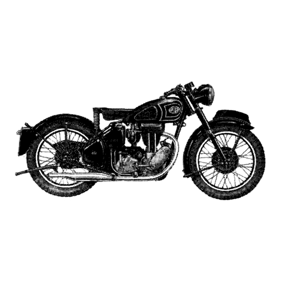
- Page 5 1951 RIGID 16M and 18 1951 SPRING 16MS and 18S 1951 RIGID C O M P E T I T I O N 16MC and 18C 1951 SPRING C O M P E T I T I O N 16MCS and 18CS...
- Page 6 All Models—93 mm. (approx.) (3·65625 in.) … … … … … … … … Engine capacity, in cubic centimetres 350 Models—51/16M, 51/16MS, 51/16MC and 51/16MCS—347 Models—51/18, 51/18S, 51/18C 51/18CS—498 Brake Liners Length W i d t h Thickness Radius Quantity off...
- Page 7 6·4 to 1 5·0 to 1 … … … 13·35 to 1 *Standard Solo sprocket for Models 16M and 16MS. †Standard Solo sprocket for Models 18 and 18S. Gear ratios (models 16MC-18C) Part Fourth gear First gear Second gear (top)
- Page 8 Solo sprocket for Model 18CS. Ignition (magneto) Ignition point before top dead centre (with control Model Make Type Point gap in fully advanced position) Rotation 16M-16MS-18 Lucas N1-4 Anti-clock ·012 in. ½ in. (39°) 16MC-18C ·012 in. Lucas Anti-clock ½ in. (39°)
- Page 9 Spokes (350 and 500 rigid and spring frame models) Length Part Location Type Gauge Quantity number underhead 5 x in. Front, left side Butted 011018 (37-X-H51) … … … … 8 x 1 0 8 8 in. Front, right side Butted 011014 (12399) …...
- Page 10 CONTROLS Throttle twist grip. On right handlebar. Twist inwards to open. When fully closed engine should just idle when hot. A i r lever. Small lever on right handlebar. Pull inwards to increase air supply to carburetter. Once set, when engine has warmed up, requires no alteration for different road speeds.
- Page 11 If any adjustment is made to the rear brake pedal make certain the brake does not bind and also see there is not excessive free pedal movement before the brake comes " on." Illustration 1 Showing Controls Before using the machine, sit on the saddle and become familiar with the position and operation of the various controls.
- Page 12 DRIVING FUEL At the time of publishing this instruction book only one grade of motor fuel (Pool Spirit) is on sale, but it may be that soon the various grades of pre-war petrol will again be avail- able when the use of best quality fuel is recommended because the small amount of economy that might be considered to accrue by using the cheaper grades is more than offset by the advantages obtained by using only Number One grades.
- Page 13 STARTING THE ENGINE (a) See that there is sufficient fuel in the petrol tank. (b) See that there is sufficient oil in the oil tank. (c) See that the gear pedal is in the neutral position. (d) Push inward the hexagonal end of off-side petrol tap slide. (e) See that the air control lever is in the fully closed position.
- Page 14 STOPPING THE ENGINE To stop the engine, close the throttle, raise the valve lifter lever and keep it raised until the engine has ceased to revolve. ON THE ROAD Having started and warmed up the engine, take the machine off the stand, sit astride it, free the clutch by pulling up the large lever on the left bar and engage the lowest gear.
- Page 15 Special attention must be given, during the running in period, to such details as valve rocker adjustment, chains, brakes, contact breaker points, and steering head bearings, all of which tend to bed down in the first hundred miles or so. Particular note must be made of the adjustment of steering head bearings, which, if run in a slack condition, will be quickly ruined.
- Page 16 CHECKING OIL CIRCULATION Provision is made to observe the oil in circulation and it is advisable to do this before each run. If the filler cap on the oil tank is removed the bent over end of the oil return pipe will be noticed some two inches below the level of the filler cap orifice and the returning oil can be seen running from it.
- Page 17 LUBRICATION LUBRICANTS TO USE Efficient lubrication is of vital importance and it is false economy to use cheap oils and greases. We recommend the following lubricants to use in machines of our make : FOR ENGINE LUBRICATION SUMMER WINTER Mobiloil D (SAE-30) (SAE-50) Mobiloil A...
- Page 18 FILLING THE GREASE GUN The standard grease gun consists of a barrel having a spring loaded end cap, to which is fixed a central steel piston in the shape of a long rod. This piston fits into a small cylinder made in one with the screwed top cap, on the end of which is the cupped nozzle that fits over the grease nipples.
- Page 19 Illustration 5 Engine Oil Circulation THE OIL TANK A N D FILTERS The level of oil in the supply tank should never be allowed to fall below the low level mark and, upon replenishment, should not be higher than one inch from the filler cap orifice, otherwise, when starting the engine, the bulk of oil in the crankcase sump may be greater than the space available in the tank.
- Page 20 A metal gauze strainer (secured to the feed pipe union) stands in the oil tank. After the first 500 miles, again at 1,000 miles, and subsequently at 5,000 mile intervals, it is recommended that the oil tank is drained, the oil filters cleaned in petrol and the tank replenished with new oil.
- Page 21 Illustration 6 The inlet valve guide is shown withdrawn as also is the inlet valve stem adjusting screw (with lock nut) PLAIN HOLE, TO ACCOMMODATE CYLIN- TAPPED HOLE, ACCOMMODATE DER HEAD RETAINING BOLT. NEEDLE SCREW. GUIDE, FOR VALVE. NEEDLE SCREW, ADJUSTING OIL FEED TO INLET VALVE.
- Page 22 GEAR BOX LUBRICATION Use one of the grades of Oils already specified. In no circumstances must heavy grease be used. Lubricant is inserted through the filler cap orifice mounted on top edge of kick-starter case cover. The gear box must not be entirely filled with oil, and, under normal conditions, the addition of two fluid ounces of oil every 1,000 miles will be sufficient.
- Page 23 BRAKE EXPANDER LUBRICATION Grease nipple on each brake expander bush. (One on each brake cover plate.) grease sparingly. Excessive grease may impair efficiency of brakes. BRAKE ROD JOINT LUBRICATION A few drops of engine oil on each brake rod yoke end pin and on the threaded portion of brake rod.
- Page 24 LUBRICATION CHART Illustration 7 Lubrication Chart Tallow Location Engine Oil Locations MAIN OIL TANK. REAR CHAIN. CONTROL LEVER MOVING PARTS. Grease Locations BRAKE ROD JOINTS. FRONT HUB. FRONT PROP, AND REAR STAND HINGE PINS. REAR HUB. FRONT CHAIN CASE. MAGNETO CHAIN CASE. GEAR BOX.
- Page 25 MAINTENANCE SADDLE ADJUSTMENT Saddle adjustment is provided at both front and rear ends. Importance is attached to the desirability of owners selecting the adjustment most to their liking. At the front end, the adjustment consists of three evenly spaced positions for the hinge bolt, accessible only upon removal of the petrol tank.
- Page 26 EVERY 1,000 MILES Drain at first 1,000 miles and re-fill with new oil. (1.) Oil tank Rear chain Remove and soak in molten tallow in bad weather. (5.) Magneto chain Inject small amount of grease through nipple in magneto chain case cover (10.) Gear box Add 2 fluid ounces of specified oil.
- Page 27 FREE SERVICE SCHEME FREE SERVICE SCHEME All owners of N E W MODELS are entitled to one FREE SERVICE A N D INSPECTION at 500 miles, or, at latest, three months after taking delivery. This service is arranged by the supplying dealer to whom the Free Service Voucher must be handed.
- Page 28 ENGINE SERVICE ACCESS For almost all service work to the upper parts of the engine, it is necessary, in order to obtain accessibility, first, to remove the petrol tank. The two petrol taps facilitate this operation by removing the need to first drain the tank of petrol. Illustration 8 Showing details and order of assembly, of the fuel tank fixing bolts and components...
- Page 29 TO REMOVE THE PETROL TANK Close both petrol taps and disconnect the petrol feed pipe from each tap. (Use two spanners, one to hold the tap and the other to unscrew the union nut on the petrol pipe.) Cut the wires interlacing the four fixing bolts. Unscrew the tank fixing bolts and the tank is then free to be taken away.
- Page 30 Inspect rubber fillet on rocker box side cover and renew if not perfect. Replace the side cover ensuring that a fibre washer is fitted under each of the three retaining nuts. Beware of over tightening these nuts, the joint being made by the rubber fillet excessive pressure is not necessary.
- Page 31 To replace valves :— After cleaning valve guide bores with rag smear each valve stem with clean oil and reverse procedure above. I M P O R T A N T N O T E :— If for any reason valve springs are re- moved from their fixing block it is important to see that upon replace- ment the spring with narrow spaced...
- Page 32 REMOVING CARBON DEPOSIT Do not use a sharp implement for removing carbon deposit from the interior of the cylinder head and the piston crown. A blunt piece of soft brass will be found quite suitable and the use of such will obviate the risk of making deep scratches. Care is necessary to avoid damaging the valve seatings and in no circumstances should any abrasive material, such as emery, or emery cloth, be used for cleaning and polishing.
- Page 33 The grinding is accomplished by smearing a thin layer of fine grinding paste (obtainable ready for use at any garage) on the valve face and then, after inserting the valve in the head, partially revolve, forwards and backwards, while applying light finger pressure to the head, raising the valve off its seat and turning to another position after every few movements.
- Page 34 Remove One gudgeon pin circlip. It is immaterial which circlip is removed. Use special pliers included in tool kit. Gudgeon pin by pushing it out of piston. Take away piston. NOTE—The gudgeon is an easy sliding fit in both piston and connecting rod small-end bush.
- Page 35 VALVE TIMING Inlet valve timing Inlet valve opens 32° before top dead centre. Inlet valve closes 63° after bottom dead centre. Exhaust valve timing Exhaust valve opens 65° before bottom dead centre. Exhaust valve closes 30° after top dead centre. (See page 92 for particulars of special timing disc graduated in degrees.) Illustration 11 Inlet Camshaft timing marks...
- Page 36 TAPPET ADJUSTMENT The top ends of the two long push rods have screwed extensions. These are locked in position by nuts, thereby providing tappet adjustment. The correct tappet clearances, on touring models, with valves closed and engine cold, is N I L (warm engine on competition models). This means the push rods should be free enough to revolve and, at the same time, there should be no appreciable up and down play.
- Page 37 TO RE-TIME THE IGNITION The maximum advance is ½" (39°). Have available a stout screwdriver, or an old type tyre lever with turned up end, and a piece of stout wire 5½" long. Before setting the ignition firing point it is essential the magneto contact breaker points are correctly adjusted.
- Page 38 Illustration 14 The rotating oil pump plunger is here shown partially with- drawn, together with the guide screw which registers in the plunger profiled groove, thereby providing the recipro- cating movement (By courtesy of " Motor Cycling ") D O W E L PEG, LOCATING TIMING GEAR TAPPED HOLE, ACCOMMODATE...
- Page 39 NOTE—Remember there is a paper washer under each oil pump end cap and, when fitting a new paper washer to the front cap, ensure the oil passage in the front cap is not obstructed by the paper washer. Make certain that the guide screw pin is correctly located in its groove (cut in the plunger) before tightening down otherwise serious damage will result when the engine is revolved.
- Page 40 Illustration 15 Showing the mixing chamber with details of the pilot jet with its air adjusting screw and the throttle stop screw...
- Page 41 CARBURETTER SERVICE The information given in this section includes all that will normally be required by the average rider. For further details, particularly those connected with racing and the use of special fuels, we refer the enquirer to the manufacturers of the carburetter, Messrs. Amal Ltd., Holford Works, Perry Barr, Birmingham.
- Page 42 CARBURETTER ADJUSTMENT To ascertain if the setting is correct, a rough test Is to warm up the engine and, with the ignition fully retarded and the air about three-quarters open, gradually open the throttle to full open, during which the engine should respond without a misfire, but, upon a sudden opening of the throttle, it should splutter and stop.
- Page 43 CARBURETTER T U N I N G INFORMATION Poor idling may be due to : Air leaks. Either at junction of carburetter and inlet port, or by reason of badly worn inlet valve stems or guides. Faulty engine valve seatings. Sparking plug faulty, or its points set too closely.
- Page 44 TRANSMISSION SERVICE THE GEAR BOX The gear box provides four speeds and has a positive foot change, operated by the right foot, and a kick-starter. It is retained to the frame by being clamped between the two engine rear plates by two bolts.
- Page 45 TO REMOVE FRONT CHAINCASE AND CLUTCH ASSEMBLY To remove outer half of front chaincase Place tray under chaincase to catch oil. Remove exhaust pipe and silencer, as one unit. Remove nut on left end of footrest rod, push rod towards the right hand side of machine sufficiently to allow footrest for left foot to be disengaged.
- Page 46 TO RE-FIT THE FRONT CHAINCASE AND CLUTCH Fit back half of front chaincase by : Place on face of crankcase boss and back face of chaincase some liquid jointing compound. Ensure the spacer is in position on the centre fixing bolt. This is located between the engine plate and the chaincase.
- Page 47 Fit the front chain and lock the clutch centre nut by : Replace the front driving chain. Ensure the spring connecting link is fitted so that the closed end of the spring clip faces the direction of rotation. Engage top gear, apply the rear brake and then fully tighten the nut that retains the clutch centre to the gear box mainshaft.
- Page 48 THE CLUTCH (See Illustration 17) It should be noted that, although the basic design of the clutch fitted to 1951 models is identical to the 1950 and earlier models, most parts have been revised in detail design, and those parts are not interchangeable with those of previous years. Clutch operating lever A is moved in direction of arrow to disengage the clutch.
- Page 49 If, to remedy clutch slip, it is necessary to screw nearly home the five nuts, this is a clear indication that, either the clutch springs have lost their strength, and/or, the fabric inserts in the clutch friction plates have worn so that they are past further useful service. In which case, replace with new.
- Page 50 Illustration 18 Details of clutch operating lever LEVER, OPERATING C L U T C H . 175-X-4 331-X SLEEVE, OR NUT, FOR OPERATING LEVER FORK. BALL (STEEL), OPERATING 67-X PLUNGER. 328-X CAP, COVERING SLEEVE (SCREWED TO KICK-STARTER CASE COVER). OPERATING PLUNGER. 330-X 333-X SCREW,...
- Page 51 FRONT CHAIN ADJUSTMENT Tighten the front chain by : Slacken : Nut on right-hand side of gear box top fixing bolt. Nut on right-hand side of gear box bottom fixing bolt. Forward nut on the adjusting eye-bolt. (Two or three turns.) Remove inspection cap from front chaincase.
- Page 52 REAR CHAIN ADJUSTMENT (Rigid Frame Models) To provide rear chain adjustment the rear wheel is bodily moved in the frame fork ends, which are open ended and slotted. Tighten rear chain by : Place machine on rear stand. Slightly slacken nuts on rear wheel solid spindle (left side first). Slacken nut on each chain adjusting bolt, two or three turns.
- Page 53 MAGNETO CHAIN ADJUSTMENT The magneto platform hinges on one of its fixing bolts. This provides sufficient move- ment for adjustment to the magneto driving chain. Tighten magneto chain by : Remove magneto chain case cover. Slacken nuts on bolts supporting magneto platform. Insert a screwdriver under that end of the magneto platform which is slotted and lever upwards until the chain tension is correct.
- Page 54 FORK & FRAME SERVICE STEERING HEAD ADJUSTMENT The steering head frame races are of the floating self-aligning type and have spherical seats. Therefore they do not fit tightly in the head lug. Occasionally test the steering head for correct adjustment by exerting pressure upwards from the extreme ends of the handlebars.
- Page 55 Introduced in early 1941, for use under strenuous war conditions by all the allied armies, it remains unaltered, except in detail, to this day, and copied practically universally. The hydraulic dampers operate in t u b u l a r members located inside the main tubes. As w i l l be seen the aluminium sliding members operate upon steel bushes attached to the b o t t o m ends of the main tubes and also upon bakelite bushes, secured to the t o p end of t h e...
- Page 56 has no o t h e r source of escape but past this sleeve and the adjacent small metered bleed hole. This intentionally restricted passage causes a considerable damper effect to the recoil action. It w i l l thus be gathered t h a t on the shock movement of the f o r k , slight damper action occurs, w i t h a greatly increased damper action on the reverse movement, b o t h actions automatically increasing in effect the more violent the movement.
- Page 57 Unscrew the hexagon plug on top of each inner tube and slacken the lock nuts securing the damper rods attached. Then, before removing the hexagon plugs, attach a piece of wire about 18 inches long underneath each damper rod lock nut, to enable the damper rods to be raised for reassembly.
- Page 58 Illustration 20...
- Page 59 REF. PART N O . NUMBER DESCRIPTION 013631 LUG, FOR HANDLEBAR A N D STEERING HEAD. 016718 BOLT, TOP, FOR FORK INNER TUBE. 010709 WASHER, PLAIN, FOR FORK INNER TUBE TOP BOLT. 010703 CAP, FOR FORK TOP COVER TUBE, TOP L O C A T I O N . 013694 TUBE, FORK COVER, TOP, RIGHT W I T H LAMP LUG.
- Page 60 REAR SUSPENSION (Spring Frame Models) The rear wheel is mounted in a fork that is hinged just behind the gear box. The hinge has robust plain bearings lubricated from a reservoir of 1½ fluid ounces (42.6 c.c.) of engine oil which is sufficient to last almost indefinitely. Provision is, however, made for replenishment should same ever be required.
- Page 61 Illustration 22 Showing " Ghost " view of " TELEDRAULIC " leg...
- Page 62 To check oil content of " TELEDRAULIC " leg and top-up : (DEALERS' SERVICE ONLY) Dealing with one leg at a time, remove top securing bolt, taking care to observe the location of the spacing washers on it. Remove bottom securing bolt and take away the leg.
- Page 63 Remove battery from carrier. Disconnect oil feed pipe from bottom of oil tank. Disconnect oil return pipe from bottom of oil tank. Disconnect vent pipe from back of oil tank. Disconnect voltage control unit from carrier side. Only two bolts to remove. need to disconnect any of the electric cables.
- Page 64 WHEELS AND BRAKES TO REMOVE FRONT WHEEL Place machine on both stands. Remove the split pin, and pin, retaining yoke end of front brake cable to the brake expander lever. Remove bolt retaining brake anchor stay to brake cover plate. Slacken the nut on the left-hand end of front wheel spindle.
- Page 65 Hold left-hand side of wheel tightly forward against the cam stop and pull backwards the right-hand side of the wheel so that the brake cover plate disengages with the square headed anchor bolt. Then, raise the hinged portion of the rear mudguard and pull wheel away from the fork ends.
- Page 66 WHEEL BEARINGS AND ADJUSTMENT The wheel bearings are of taper roller type. The inner bearings for the rollers are integral with the wheel spindle in the case of the front wheel, and are separate tracks that are threaded on the centre spindle in the case of the rear wheel, (Reference to Illustration 24 will make that clear.) The outer cups for the rollers are pressed into the...
- Page 67 To re-fit, reverse the above procedure, remembering that, after cup (6), washer (5), spacer (4), oil seal (3) and washer (2) have been inserted in the plain end of the hub, to re-fit the circlip (I) and then carefully to apply steady pressure on the inner edge of the cup (6) to force the above entire assembly tightly back against the circlip (1).
- Page 68 Illustration 24 Showing exploded view of hub bearing components in the order of assembly. Upper part is that of front bearings (Rigid and Spring Frame Models). Lower part is that of rear bearings (Spring Frame Model only) (Rigid Frame Models Identical except for items 28 to 32) CIRCLIP.
- Page 69 TO DISMANTLE A REAR WHEEL BEARING These instructions need reference to the lower part of Illustration 24. Remove wheel from machine. Remove brake cover plate, with brake shoes, centre solid spindle with cams, spacers, bushes, nut and speedometer gear box. Turn to left-hand side and slacken lock nut (26).
- Page 70 BRAKE DRUMS The front wheel brake drum is retained to the wheel by ten countersunk screws. The rear wheel brake drum is integral with the rear wheel sprocket and is retained to the wheel hub by five bolts and nuts. Under each nut is a lock washer of the "...
- Page 71 Centralise brake shoes by : Ensure the nut binding the cover plate to the wheel spindle is slightly slack. Place on the brake expander lever a tubular spanner (to increase the leverage), and, while maintaining pressure on the tubular spanner (to expand fully the brake shoes), fully tighten the spindle nut binding the cover plate to the spindle.
- Page 72 Adjust rear brake by : Place machine on centre stand if spring frame, otherwise on rear stand. Screw further on the brake rod the knurled adjusting nut till, by rotating the wheel, it can be felt the brake shoes are just touching the brake drum. Then unscrew the adjusting nut two complete turns.
- Page 73 Illustration 29 Showing brake rod ad- justment exhausted, in- dicating need brake thrust pin adjust- ment. (SPRING FRAME MODELS) TYRES A N D SERVICE Obtaining satisfactory life and service from the tyres is largely a matter within the user's control because the first essential is correct inflation. Check tyre pressures with a low pressure gauge at least once a week.
- Page 74 TYRE REMOVAL It is not essential to remove a wheel from the machine to repair a puncture but it will usually be found desirable and more convenient to do so. Take off outer cover and remove inner tube by : Remove cap from tyre valve.
- Page 75 TYRE PRESSURES The following are correct minimum inflation pressures for specified loads per tyre : Load per tyre, 200 lb. Pressure 16 lb. per square inch 240 lb. 18 lb. 280 lb. 20 lb. 350 lb. 24 lb. 400 lb. 28 lb.
- Page 76 ELECTRICAL SERVICE ELECTRICAL EQUIPMENT LUCAS electrical equipment is fitted and this comprises three independent electrical circuits, as follows : (1) IGNITION—Magneto, High-tension wire and Sparking plug. (2) CHARGING—Dynamo, Automatic Voltage Control Unit and Battery. (3) L I G H T I N G A N D ACCESSORIES—Lamps, Horn, Switches and wiring. IGNITION CIRCUIT A LUCAS type N1-4 magneto is fitted (Type NR1 to competition models) and the only service attention this requires is occasional lubrication of the contact breaker cam...
- Page 77 Lubricate contact breaker cam and tappet by : Remove contact breaker as described on page 74. Saturate, with a few drops of thin machine oil, the wick mounted in the core of its carry- ing screw B, Illustration 30. Push out of the contact breaker body the tappet B, Illustration 31, wipe it with a soft cloth, smear it with thin machine oil and then replace it.
- Page 78 The foregoing instructions do not apply to competition models fitted with Racing Magnetos Type NR1. SPECIAL NOTE—Check the contact breaker point gap after the first one hundred miles and five hundred miles. Owing to the initial settling down, there is a tendency for the gap to alter in the first few hundred miles of use.
- Page 79 CHARGING A LUCAS type E3-N dynamo is fitted. It is anti-clockwise in rotation. cutting in speed is 1250-1500 r.p.m. at 7 volts and at 1,850 to 2,200 revolutions per minute it gives an output of 5 amps at 7 volts. The replacement part number is 20028A. The positive brush is insulated and the negative brush is earthed.
- Page 80 TO REMOVE DYNAMO Remove Magneto chain cover, (Retained by 6 screws.) Remove nut and its washer fixing each magneto chain sprocket. Using a sprocket withdrawal tool, or wedges behind sprocket, release, in turn, each magneto chain sprocket and take them away, complete with chain. Remove timing gear cover (retained by 5 screws) taking care not to allow the two camshafts to come out of engagement with the small timing pinion.
- Page 81 The regulator and cut-out are accurately set during manufacture. If, under normal running-conditions, it is found that the battery is continually in a low state of charge, or is being constantly over-charged, then the regulator setting should be checked by a qualified electrician and, if necessary, re-set.
- Page 82 The specific gravity of the electrolyte indicates the state of charge of the battery. With a fully charged battery the specific gravity of the electrolyte should be 1·280 to 1·300. Check the gravity by means of a hydrometer, and if it is below 1·150 the battery should be charged as soon as possible by the normal running of the motor cycle.
- Page 83 LIGHTING A N D ACCESSORIES Headlamp A LUCAS type SSU-700-P headlamp is fitted. The replacement part number is 50945-A. It has a panel mounted on its top, retained by three screws, in which is the main switch and ammeter and it also supports the cable harness. See Illustration 35.
- Page 84 To replace the headlamp rim and light unit Lay the light unit in the rim so that the location block on the unit back engages with the forked bracket on the rim. Replace, by springing in, the spring clips so that they are evenly spaced around the rim. To replace the back shell engage the projections on the inside of the back shell with the slots in the holder, press on and secure by twisting it to the right.
- Page 85 Screwed wire connector A LUCAS screwed connector of the type shown in Illustration 37 is used in the wire connecting the positive terminal of the battery to the input side of the ammeter (the wire has yellow and black coloured sleeves) in the head lamp. It is made up of four parts.
- Page 86 MAIN BULB PILOT BULB AMMETER LIGHTING SWITCH DIPPER SWITCH SPEEDO ILL. HORN PUSH DYNAMO TO SPARKING PLUG SNAP MAGNETO CONNECTOR REGULATOR BATTERY BATTERY CONNECTOR (NEGATIVE EARTH) HORN TAIL LAMP Illustration 38 Wiring diagram (See page 96 for key to the cable numbers and colours.)
- Page 87 USEFUL INFORMATION In the following five paragraphs are particulars of failures and troubles that can occur, together with the probable reasons. These troubles are arranged in the order of their probability. TRACING TROUBLES Engine fails to start, or is difficult to start, may be due to : Throttle opening too large.
- Page 88 Engine overheats may be due to : Lack of proper lubrication. (Quality or quantity of oil.) Faulty sparking plug. Air control to carburetter out of order. Punctured carburetter float. Engine carbonised. Weak valve springs. Pitted valve seats. Worn piston rings. Ignition setting incorrect.
- Page 89 CLEANING THE MACHINE Do not attempt to rub, or brush, mud off the enamelled surfaces because this will soon destroy the sheen of the enamel. Mud, and other road dirt, should be soaked off with water. The best method is to use a small hose, taking care not to direct water on to the engine, carburetter, magneto and other such parts.
- Page 90 Parts sent to us as patterns, or for repair, should have attached to them a label bearing the sender's full name and address. The instructions regarding such parts should be sent under separate cover. If it is necessary to bring a machine, or parts, to the Works for an urgent repair, IT IS ESSENTIAL you MAKE AN APPOINTMEN T beforehand to A V O I D DISAPPOINT- MENT.
- Page 91 SERVICE The Service and Repair Department is situated in Burrage Grove, Plumstead, London, S.E.18. and is open on Mondays to Fridays from 8.30 a.m. to 12.55 p.m.—2.0 p.m. to 5.30 p.m. It is closed on Saturdays, Sundays and National Holidays. It exists for the purposes of : (a) Giving technical assistance verbally or through the post.
- Page 92 THE MACHINE A N D THE L AW Every motor cycle used on the public roads must be registered and carry the registration numbers and licence disc allotted to it. The dealer, from whom the machine is bought, will, generally, attend to all matters legally essential before it is used on the public roads. To register a new machine Send to the Local Registration Authority the following : (a) Form "...
- Page 93 GUARANTEE We give the following guarantee with our motorcycles, motorcycle combinations and sidecars, which is given in place of any implied conditions, warranties or liabilities whatsoever, statutory or otherwise, all such implied conditions, warranties and liabilities being in all cases excluded. statement, description, condition or representation contained in any catalogue, advertisement, leaflet or other publication shall not be construed as enlarging, varying or overriding this guarantee.
- Page 94 TOOLS AND SPECIAL EQUIPMENT TOOLS The standard tool kit, issued with each new machine, contains : 017253 Tool bag. 017114 Tyre inflator. 017007 Tyre levers. 017248 Pliers. 011188 Gudgeon pin circlip pliers. 017256 Screwdriver. 017246 Grease gun. 017249 Adjustable wrench. 017252 Sparking plug box spanner and tommy bar.
- Page 95 BADGES Neat monogram badges are now available at a cost of 1/6, plus 6d. postage. They can be supplied as a tie pin, as a brooch or for fitting in a button hole. When ordering state type required. Illustration 39...
- Page 96 ILLUSTRATIONS Illustrations Page Battery … … … … … … … … … Brake adjustment, front … … … … … … … Brake adjustment, rear (rigid frame) … … … … … … … … … Brake adjustment, rear (spring frame) Brake shoe adjustment …...
- Page 97 INDEX Carburetter Service … … … … … … … … Controls … … … … … … … … … … … … Data … … … … … … … … … … … Driving … … … …...
- Page 98 COLOURED IDENTIFICATION BANDS ON NUMBERED CABLES SHOWN IN THE WIRING D I A G R A M ON PAGE 84. BLUE and WHITE RED and BLACK WHITE and PURPLE YELLOW GREEN and BLACK YELLOW and BLACK PURPLE BLACK BLUE GENUINE A •...
Need help?
Do you have a question about the 16M and is the answer not in the manual?
Questions and answers