
Related Manuals for Hatz 1B20


Summary of Contents for Hatz 1B20
- Page 1 CREATING POWER SOLUTIONS. 1B20 | 1B27 | 1B30 | 1B40 | 1B50 OPERATOR'S MANUAL Diesel engine Hatz Diesel www.HATZ-DIESEL.com...
-
Page 3: Table Of Contents
1B20, 1B27, 1B30, 1B40, 1B50 Table of contents Table of contents Notices ......................... 5 General information .................... 6 Safety ........................ 7 General information.................... 7 3.1.1 Intended use and foreseeable misuse .............. 7 3.1.2 Machine user or machine manufacturer obligations .......... 8 3.1.3... - Page 4 Table of contents 1B20, 1B27, 1B30, 1B40, 1B50 Refueling ...................... 50 Checking the water separator ................ 52 Check the air filter warning indicator (option)............ 54 Maintenance ...................... 55 General maintenance instructions............... 55 Maintenance work .................... 56 8.2.1 Maintenance notice label .................. 56 8.2.2...
-
Page 5: Notices
1B20, 1B27, 1B30, 1B40, 1B50 Notices Notices Contact data © 2016 Motorenfabrik HATZ Ernst-Hatz-Straße 16 94099 Ruhstorf Germany Tel. +49 (0)8531 319-0 Fax +49 (0)8531 319-418 marketing@hatz-diesel.de www.hatz-diesel.com All rights reserved! Copyright The copyright for this Operator's Manual rests entirely with Motorenfabrik HATZ, Ruhstorf. -
Page 6: General Information
HATZ tools. The global HATZ service network is at your disposal to ad- vise you and supply you with spare parts. For the address of the Hatz ser- vice station nearest you, please see the directory included or visit the inter- net at: www.hatz-diesel.com... -
Page 7: Safety
Any other use is not intended and therefore not permitted. Violations com- promise the safety of the personnel working with the machine. Responsibility is not accepted by Motorenfabrik HATZ for damage resulting from this situa- tion. The operational safety of the machine is only guaranteed if it is used as in- tended. -
Page 8: Machine User Or Machine Manufacturer Obligations
Machine manufacturer obligations If you have an engine that is not yet installed in a machine, it is imperative that you follow the Assembly Instructions for HATZ Diesel Engines be- fore installing the engine. These assembly instructions contain important in- formation on how to safely install the engine and are available at your near- est HATZ service station. -
Page 9: Representation Of Safety Notes
1B20, 1B27, 1B30, 1B40, 1B50 Safety Obligations of the operating and maintenance personnel Personnel assigned with operating and maintaining the machine must have read and understood the Operator's Manual or must possess the qualifica- tions necessary for working with this equipment, acquired in training/instruc- tional courses. -
Page 10: Meaning Of Safety Symbols
Safety 1B20, 1B27, 1B30, 1B40, 1B50 Signal words Signal words identify the magnitude of the risk and the seriousness of the possible injuries: Danger symbol/ Meaning signal word This signal word is used to indicate imminently DANGER dangerous situations which, if not avoided, will lead to serious injury or death. - Page 11 1B20, 1B27, 1B30, 1B40, 1B50 Safety Symbol Meaning Warning of explosive substances! Warning of toxic engine exhaust! Warning of corrosive substances! Warning of heavy loads! Warning of environmental damage! Comply with the Operator's Manual or additional documenta- tion from other manufacturers or the user! Additional information that is useful to the reader.
-
Page 12: Safety Notes
Safety 1B20, 1B27, 1B30, 1B40, 1B50 Safety notes 3.2.1 Operational safety Introduction This chapter contains all of the important safety instructions for personal pro- tection and for safe and reliable operation. Additional, task-related safety in- structions can be found at the beginning of each chapter. - Page 13 The warning labels and information signs on the machine must be followed (see chapter "Labels" 3.3 Labels, page 20). The warning labels and information signs must be kept legible and must be replaced if necessary. For this purpose, contact your nearest HATZ service station. Maintenance work...
- Page 14 Safety 1B20, 1B27, 1B30, 1B40, 1B50 General safety instructions DANGER Danger to life and danger of injury due to failure to follow the warnings on the machine and in the Operator's Manual. ▪ Heed the warnings on the machine and in the Operator's Manual.
-
Page 15: Machine-Specific Safety Instructions For Operation
If you have an engine that is not yet installed in a machine, it is imperative that you follow the Assembly Instructions for HATZ Diesel Engines be- fore installing the engine. These assembly instructions contain important information on safe installa- tion. -
Page 16: Machine-Specific Safety Instructions For Maintenance Work
Replacing parts ▪ When replacing defective components, we recommend that you use gen- uine HATZ original spare parts (see chapter 2 General information, page ▪ When disposing of parts that can no longer be used, do so in accordance with local environmental regulations or send them to a recycling center. - Page 17 1B20, 1B27, 1B30, 1B40, 1B50 Safety Measures following maintenance and troubleshooting ▪ Securely reconnect loose electrical connections; check that the electrical components and equipment are functioning properly. ▪ Check the entire machine for foreign bodies; remove any foreign bodies. Safety instructions for maintenance work DANGER Danger of explosion from flammable cleaning agents.
-
Page 18: Electrical Equipment
Safety 1B20, 1B27, 1B30, 1B40, 1B50 3.2.4 Electrical equipment Safety notes DANGER Danger to life, danger of injury or danger of property dam- age due to incorrect use of batteries. ▪ Do not place tools on the battery. ▪ Before performing work on the electrical equipment, always disconnect the negative battery terminal. - Page 19 1B20, 1B27, 1B30, 1B40, 1B50 Safety NOTICE ▪ The necessary wiring diagrams are included with the ma- chine if it is equipped with electrical equipment. Additional wiring diagrams can be requested when needed. ▪ We cannot be held liable for electrical equipment that is not designed according to HATZ wiring diagrams.
-
Page 20: Labels
Safety 1B20, 1B27, 1B30, 1B40, 1B50 Labels Warning labels and information signs on the engine Label Meaning Maintenance instructions (see chap- 1B20: 0,20mm 1B27: 0,10mm 1B30: 0,10mm 1B40: 0,10mm 1B50: 0,10mm ter 8.1 General maintenance instruc- tions, page 55) 0000 051 104 06... - Page 21 1B20, 1B27, 1B30, 1B40, 1B50 Safety Label Meaning Speed adjustment with connecting rod (additional equipment) Refuel with diesel fuel only. For the specification, see chapter 4.5 Fuel, DIESEL page 26 052 356 02 Do not use bio diesel. Changing the fuel filter (see chapter 8.2.11 Changing the...
-
Page 22: Technical Data
Technical data 1B20, 1B27, 1B30, 1B40, 1B50 Technical data Engine information and filling quantities Type 1B20 1B27 1B30 1B40 1B50 Type Air cooled four stroke diesel engine Combustion system Direct injection Number of cylinders Bore/stroke 69 / 65 74 / 65... -
Page 23: Engine Type Plate
1B20, 1B27, 1B30, 1B40, 1B50 Technical data Screw tightening torque Designation Oil drain screw Engine type plate ➀ ➁ ➂ ➃ The engine type plate is located on the sound protection hood and contains the following engine information: Number of the engine family or the EU approval (for engines with ex- haust certificate only) Engine type, customer specification and setting of pumping start (°... -
Page 24: Physical Operating Conditions
Technical data 1B20, 1B27, 1B30, 1B40, 1B50 The following data must always be specified for requests and spare part or- ders Engine type and customer specification Engine serial number Max. engine speed (rpm) Physical operating conditions Engine adjustment The engine is normally adjusted to operate within the standard reference conditions stipulated in ISO 3046-1:... -
Page 25: Engine Oil
1B20, 1B27, 1B30, 1B40, 1B50 Technical data Engine oil Oil quality All brand name oils that satisfy at least the following specification are suit- able: ▪ ACEA – B3 / E4 or better ▪ API – CF / CH-4 or better If engine oils of a low quality standard are used, the oil change interval must be reduced to 150 operating hours. -
Page 26: Fuel
Technical data 1B20, 1B27, 1B30, 1B40, 1B50 Fuel Fuel type All types of diesel fuel that meet the minimum requirements of the following specifications are suitable: ▪ EN 590 or ▪ BS 2869 A1 / A2 or ▪ ASTM D 975- 1D / 2D CAUTION Danger of engine damage from low quality fuel. -
Page 27: Engine Design
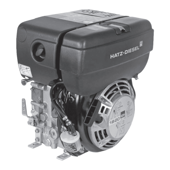
1B20, 1B27, 1B30, 1B40, 1B50 Engine design Engine design Overview Type plate Cylinder head cover Silencer with contact protection Exhaust manifold with exhaust screen Oil pressure switch Starter Voltage regulator Crankshaft – power take-off (pto) Oil drain screw Speed control lever... - Page 28 Engine design 1B20, 1B27, 1B30, 1B40, 1B50 Recoil start Stop pin (option) Dry air filter Lifting eye Fuel cap Sound protection hood Only in model with electrical equipment. The engine can optionally be supplied with an external instrument box. Operator's Manual...
-
Page 29: Transport, Assembly And Commissioning
▪ Only transport the machine when it is switched off and has cooled down. ▪ If you have questions on transporting the machine, please contact your nearest HATZ service station. For contact data, see chapter 1 Impres- sum, page 5 or www.hatz-diesel.com. -
Page 30: Installation Notes
Installation notes HATZ diesel engines are efficient, robust and have a long service life. There- fore, they are usually installed in machines that are used for commercial pur- poses. The machine manufacturer must follow the applicable regulations regarding machine safety –... -
Page 31: Preparations For Commissioning
▪ After the engine is installed in the machine, rotating parts must be pro- tected against contact. HATZ safety equipment is available for the belt drive of the cooling fan and alternator. ▪ Comply with all notices and warning labels on the engine and keep them in a legible condition. -
Page 32: Filling Engine Oil (First Filling)
Transport, assembly and commissioning 1B20, 1B27, 1B30, 1B40, 1B50 Filling engine oil (first filling) Engines are normally delivered without an engine oil filling. Safety notes CAUTION Danger of injury Prolonged contact with engine oil can lead to irritation of the skin. -
Page 33: Filling The Oil Bath Air Filter (Option)
1B20, 1B27, 1B30, 1B40, 1B50 Transport, assembly and commissioning Step Activity Reinsert the dipstick and screw it tight. Unscrew the dipstick and check the oil level. If required, top up engine oil to the max. mark. Reinsert the dipstick and screw it tight. -
Page 34: Operation And Use
Operation and use 1B20, 1B27, 1B30, 1B40, 1B50 Operation and use Safety notes NOTICE Comply with the safety chapter! Follow the basic safety instructions in chapter 3 Safety, page 7. WARNING Danger of injury from damage and defects on the machine. -
Page 35: Performing Tests
1B20, 1B27, 1B30, 1B40, 1B50 Operation and use Max. permissible forces on the speed control lever and stop pin F < 15 N STOP < 30 N < 76.5° STOP START Performing tests Before starting Before starting the engine, several tests need to be performed to ensure the machine is working properly. -
Page 36: Setting The Speed Control
Operation and use 1B20, 1B27, 1B30, 1B40, 1B50 Setting the speed control Safety note CAUTION Damage to the diesel engine due to inadequate lubrication. ▪ After the engine has been out of use for an extended period (approx. 6 months or longer) or when the engine is first taken into service, operate the engine at a low set speed and without a load for approx. -
Page 37: Starting The Engine
1B20, 1B27, 1B30, 1B40, 1B50 Operation and use Starting the engine Starting options A hand start mechanism is standard equipment for the engine. A starter can be installed as an option. If possible, separate the engine from the machine being driven by uncou- pling it. -
Page 38: Starting The Engine With Recoil Start (Up To -6 °C)
Operation and use 1B20, 1B27, 1B30, 1B40, 1B50 7.4.1 Starting the engine with recoil start (up to -6 °C) Overview Grip Recoil start cover Diagram of starting procedure Procedure Step Activity Check the speed adjustment (see chapter 7.3 Setting the speed control, page 36). -
Page 39: Starting The Engine With A Starter
1B20, 1B27, 1B30, 1B40, 1B50 Operation and use NOTICE When the exhaust emits white smoke after several failed start procedures: ▪ Move the speed controller lever to the "Stop" position. ▪ Pull the starting rope all the way out five times. - Page 40 Switch off the engine immediately! Danger of engine damage. Check the oil level (see chapter 7.6 Checking the oil level and adding oil if necessary, page 47). Contact Hatz service if the oil level is correct. Engine temperature display Switch off the engine immediately! Danger of engine damage.
- Page 41 1B20, 1B27, 1B30, 1B40, 1B50 Operation and use Overview – Fuel shut-off valve (option) Fuel shut-off valve Description of functions When the starting key is moved to position I the fuel shut-off valve (1) is electrically unlocked. The fuel supply to the injection pump is enabled, the engine is ready to start.
- Page 42 Operation and use 1B20, 1B27, 1B30, 1B40, 1B50 Step Activity Insert the starting key all the way and turn to position "I". When the pre glow display (3) lights up, wait until it goes out then continue with step 3.
-
Page 43: Switching Off The Engine
1B20, 1B27, 1B30, 1B40, 1B50 Operation and use Step Activity Turn the starting key back to position "I". The fault display lights up again. Remedy the fault before making further starting attempts (see chapter 9.1 Troubleshooting, page 86). The indicator then goes out at the next start. - Page 44 Operation and use 1B20, 1B27, 1B30, 1B40, 1B50 Overview Speed control lever Stop pin (additional equipment) Connecting rod (additional equipment) Procedure Step Activity Speed control lever Push the speed control lever (1) all the way to the "STOP" po- sition. The engine switches off.
-
Page 45: Switching Off The Engine (Electrical)
1B20, 1B27, 1B30, 1B40, 1B50 Operation and use 7.5.2 Switching off the engine (electrical) Overview — HATZ instrument boxes Standard Option HATZ Operator's Manual... - Page 46 Operation and use 1B20, 1B27, 1B30, 1B40, 1B50 Fuel shut-off valve Protective cap Starting key Fuel shut-off valve Ignition lock Operation Procedure Step Activity Turn the starting key (2) to position "0". ▪ The fuel shut-off valve shuts off the fuel supply to the injection pump.
-
Page 47: Checking The Oil Level And Adding Oil If Necessary
1B20, 1B27, 1B30, 1B40, 1B50 Operation and use Checking the oil level and adding oil if necessary Safety notes CAUTION Danger of burns. There is a danger of burns when working on a hot engine. ▪ Wear safety gloves. CAUTION... -
Page 48: Engine Oil Level
Operation and use 1B20, 1B27, 1B30, 1B40, 1B50 7.6.1 Engine oil level Overview Dipstick Oil refilling container Procedure Step Activity Switch off the engine and wait several minutes for the engine oil to collect in the crankcase. Engine must be level. -
Page 49: Oil Level In The Oil Bath Filter (Option)
1B20, 1B27, 1B30, 1B40, 1B50 Operation and use 7.6.2 Oil level in the oil bath filter (option) Overview Clamp fastener (2x opposing) Oil container Filter insert Gasket Level mark Procedure Step Activity Release the clamp fasteners (1). Remove the oil container (2). -
Page 50: Refueling
Operation and use 1B20, 1B27, 1B30, 1B40, 1B50 Refueling Safety notes DANGER Fire hazard from fuel. Leaked or spilled fuel can ignite on hot engine parts and cause serious burn injuries. ▪ Only refuel when the engine is switched off. - Page 51 1B20, 1B27, 1B30, 1B40, 1B50 Operation and use Overview Fuel cap Fuel tank Procedure Step Activity Figure Open the fuel cap. Fill the fuel tank with diesel fuel. HATZ Operator's Manual...
-
Page 52: Checking The Water Separator
Operation and use 1B20, 1B27, 1B30, 1B40, 1B50 Step Activity Figure Close the fuel cap. NOTICE ▪ Before starting for the first time or if the fuel system is empty, fill the fuel tank fully with diesel fuel. This causes the fuel system to be bled automatically. - Page 53 1B20, 1B27, 1B30, 1B40, 1B50 Operation and use Overview Water in the fuel tank collects at the lowest point of the fuel tank in the water separator. Standard Model with window Drain screw, hex (standard) Window (additional equipment) Drain screw (manually operated)
-
Page 54: Check The Air Filter Warning Indicator (Option)
Operation and use 1B20, 1B27, 1B30, 1B40, 1B50 Check the air filter warning indicator (option) Overview Rubber bellow Green field Procedure Step Activity Bring the engine briefly to maximum speed. When the rubber bellow (1) contracts and covers over the green field (2), immediately check the air filter system (see chapter 8.2.12 Maintaining the dry air filter, page 83). -
Page 55: Maintenance
▪ Problems may occur if unsuitable spare parts have been installed. We cannot accept responsibility for damage and secondary damage that result from this. We therefore recommend the use of genuine Hatz original spare parts. ▪ Closely adhere to the maintenance conditions prescribed in this Operators Manual. -
Page 56: Maintenance Work
▪ After the necessary maintenance and repair work is completed, perform a function test (test run). ▪ For maintenance work that is not listed and described in the maintenance documentation, please contact your nearest HATZ service station. Maintenance work Safety note... -
Page 57: Maintenance Plan
1B20, 1B27, 1B30, 1B40, 1B50 Maintenance 1B20: 0,20mm 1B27: 0,10mm 1B30: 0,10mm 1B40: 0,10mm 1B50: 0,10mm 0000 051 104 06 250h = 1h 500h 8.2.2 Maintenance plan In new and generally overhauled engines, after 25 operating hours: ▪ Change the engine oil ▪... -
Page 58: Checking The Intake Area
Maintenance 1B20, 1B27, 1B30, 1B40, 1B50 Symbol Maintenance in- Maintenance activity/check Chapter terval Every 8–15 oper- Check the oil level. 7.6 Checking the ating hours or ev- oil level and ery day before adding oil if nec- starting essary, page 47 Check the engine oil level in 7.6.2 Oil level in... - Page 59 1B20, 1B27, 1B30, 1B40, 1B50 Maintenance Symbol Maintenance in- Maintenance activity/check Chapter terval Every 500 operat- Change the fuel filter. 8.2.11 Changing 500h ing hours the fuel filter, page 78 Maintain the dry air filter. 8.2.12 Maintain- ing the dry air fil-...
-
Page 60: Change The Engine Oil
Maintenance 1B20, 1B27, 1B30, 1B40, 1B50 Intake area of cyclone precleaner Dust outlet opening Intake area of oil bath filter Procedure Step Activity Check the air intake opening (1) for coarse contamination such as leaves, heavy dust deposits, etc., and clean if necessary. - Page 61 1B20, 1B27, 1B30, 1B40, 1B50 Maintenance CAUTION Danger of injury Prolonged contact with engine oil can lead to irritation of the skin. ▪ Wear safety gloves. ▪ If there is contact with the skin, thoroughly wash the af- fected areas of the skin with soap and water.
-
Page 62: Clean The Oil Filter
Maintenance 1B20, 1B27, 1B30, 1B40, 1B50 Procedure Step Activity Keep a container ready for collecting the used oil. The con- tainer must be large enough to hold the entire amount of en- gine oil. Unscrew the oil drain screw (1) and drain the oil entirely. - Page 63 1B20, 1B27, 1B30, 1B40, 1B50 Maintenance NOTICE ▪ Capture emerging oil in a suitable container. ▪ Dispose of the oil according to legal regulations. NOTICE ▪ The oil filter should be cleaned when the engine oil is changed (see chapter 8.2.4 Change the engine oil, page 60), since oil will run out when the filter is pulled out.
- Page 64 Maintenance 1B20, 1B27, 1B30, 1B40, 1B50 Step Activity Figure Blow out the oil filter with com- pressed air from the inside to the outside. Check the gasket (3) for dam- age and renew if necessary. Lightly oil the gaskets (3+4) before mounting.
-
Page 65: Check And Set The Tappet Clearance
▪ Preparations on engine model with dry air filter ▪ Preparations on engine model with oil bath filter ▪ Preparations on engine model with rammer operation (1B20 R) Preparation - Engine model with dry air filter Step... - Page 66 Step Activity Figure Release the screw (1). Take off the cover plate (2) with the sound protection hood (3). Preparations - Engine model with rammer operation (1B20 R) Step Activity Figure Unscrew the air filter cap (1). Operator's Manual HATZ...
- Page 67 Activity Figure Remove dirt in the area of the cylinder head cover (1). Remove the screws (2). (2 screws in 1B20, 1B27 and 1B30, 3 screws in 1B40 and 1B50). Take off the cover (3) with the gasket (4). HATZ...
-
Page 68: Maintaining The Oil Bath Filter
Maintenance 1B20, 1B27, 1B30, 1B40, 1B50 Step Activity Figure Turn the engine in the sense of rotation until the rocker arm (1) has fully opened the outlet valve. Then check the tappet clearance at the rocker arm (2) with a feeler gauge (3). For the setting, see the chapter 4.1... - Page 69 1B20, 1B27, 1B30, 1B40, 1B50 Maintenance CAUTION Danger of injury Prolonged contact with engine oil can lead to irritation of the skin. ▪ Wear safety gloves. ▪ If there is contact with the skin, thoroughly wash the af- fected areas of the skin with soap and water.
-
Page 70: Clean The Cooling Air Area
Maintenance 1B20, 1B27, 1B30, 1B40, 1B50 Procedure – Cleaning the oil bath air filter Step Activity Figure Remove the oil container (1). Remove the dirty oil and sludge and clean the con- tainer. Rinse the filter insert (2) in diesel fuel. Before assembling the filter, drip or wipe dry. - Page 71 1B20, 1B27, 1B30, 1B40, 1B50 Maintenance Procedure Step Activity Figure Dry contamination Remove the screws (1). Take off the recoil start (2) and clean it. Clean the fan blades with a suitable brush. Then blow it out with com- pressed air.
- Page 72 Check the air gap (5) for dirt and clean with compressed air if necessary. Note: In 1B20 and 1B27, the air gap (5) is markedly smaller than the gap shown in the figure (size approx. 5 mm). The element can be checked and cleaned through the holes in the contact guard.
-
Page 73: Check The Screw Connections
1B20, 1B27, 1B30, 1B40, 1B50 Maintenance 8.2.9 Check the screw connections NOTICE ▪ Do not retighten the screws for attaching the cylinder head. ▪ The adjustment screws on the speed governor and the in- jection system are secured with locking varnish and are not permitted to be tightened or adjusted. - Page 74 The exhaust screen can be cleaned in different ways depending on how the engine is equipped: ▪ Cleaning the exhaust screen in standard models ▪ Cleaning the exhaust screen in models for rammer operation (1B20 R) Cleaning the exhaust screen in standard models Step...
- Page 75 1B20, 1B27, 1B30, 1B40, 1B50 Maintenance Step Activity Figure Remove the deposits in the screen insert with a suitable wire brush. Check the screen insert for cracks or breakage, and re- place if necessary. Mount the screen insert and bracket again.
- Page 76 Maintenance 1B20, 1B27, 1B30, 1B40, 1B50 Clean the exhaust screen in models for rammer operation (1B20 R) Step Activity Figure Release the hex nut and take off the exhaust manifold (1). Remove the hex nut from the bracket (2) and pull out the screen insert (3).
- Page 77 1B20, 1B27, 1B30, 1B40, 1B50 Maintenance Step Activity Figure Pull the hose (4) off of the ex- haust manifold. Check that the pipe connection (5) is clear. Remove deposits using a screwdriver or similar instrument. Attach the hose again. Mount the screen insert and bracket again.
-
Page 78: Changing The Fuel Filter
Maintenance 1B20, 1B27, 1B30, 1B40, 1B50 Step Activity Figure Insert the exhaust manifold with the bracket (2) into the hole and pull it back to the out- side so that the bracket can no longer become unhooked. Tighten the hex nut. - Page 79 1B20, 1B27, 1B30, 1B40, 1B50 Maintenance CAUTION Dirt particles can damage the injection system. ▪ Maintain clean conditions to ensure dirt does not enter the fuel line. Procedures The fuel filter can be changed in different ways depending on how the en- gine is equipped: ▪...
- Page 80 Maintenance 1B20, 1B27, 1B30, 1B40, 1B50 Model with double fuel filter system NOTICE ▪ The advantage of this system is that dirt particles that may enter the fuel line during a filter change are captured by the downstream outside filter and are therefore unable to en- danger the injection system.
- Page 81 1B20, 1B27, 1B30, 1B40, 1B50 Maintenance Step Activity Figure Close the fuel cap. The fuel system is bled auto- matically. Model with external fuel filter NOTICE In the model with an external fuel filter, there is no fuel filter in the tank.
- Page 82 Maintenance 1B20, 1B27, 1B30, 1B40, 1B50 Step Activity Figure Place a suitable container un- der the fuel filter to collect the remaining fuel. Pull the fuel line (4) off of the fuel filter (5) on both sides and insert a new filter.
-
Page 83: Maintaining The Dry Air Filter
1B20, 1B27, 1B30, 1B40, 1B50 Maintenance 8.2.12 Maintaining the dry air filter NOTICE ▪ Immediately clean the filter cartridge if the maintenance dis- play appears at maximum speed. ▪ Renew the filter cartridge after a use period of 500 operating hours. -
Page 84: Checking And Cleaning The Air Filter Cartridge
Maintenance 1B20, 1B27, 1B30, 1B40, 1B50 Step Activity Figure The air filter cartridge either needs to be replaced, or cleaned or checked depend- ing on the degree of contam- ination (see chapter 8.2.13 Checking and cleaning the air filter cartridge, page 84). - Page 85 1B20, 1B27, 1B30, 1B40, 1B50 Maintenance Checking and cleaning the air filter cartridge Step Activity Figure Dry contamination Blow out the filter cartridge (1) with dry compressed air from the inside to the outside until dust no longer emerges. Check the sealing surface (2) of the filter cartridge for damage.
-
Page 86: Faults
General troubleshooting notes If the cases listed below have been worked through but the fault continues to persist, please contact your nearest Hatz service station. The engine does not start or is difficult to start, but can be turned easily as... - Page 87 1B20, 1B27, 1B30, 1B40, 1B50 Faults If equipped with a fuel shut-off valve or electrical automatic shutoff (engine does not start) Possible causes Remedy Chapter The fuel shut-off valve Contact Hatz Service. is not functional and/or irregularities in the electrical equipment.
- Page 88 Check the oil level. 7.6 Checking the oil level and adding oil if nec- essary, page 47 ▪ Faulty AC alternator. Contact Hatz Service. ▪ Engine temperature Check the cooling air guides 8.2.8 Clean the too high. for contamination or other im- cooling air area, pairments.
- Page 89 70 ▪ Faulty AC alternator. Contact Hatz Service. Fault signal from the overvoltage and polarity protection system in the voltage regulator: ▪ Battery and/or other Check the electrical equipment 3.2.4 Electrical...
- Page 90 Faults 1B20, 1B27, 1B30, 1B40, 1B50 Possible causes Remedy Chapter ▪ Fuel filter is clogged. Change the fuel filter. 8.2.11 Changing the fuel filter, page 78 ▪ Inadequate tank Ensure that the tank is suffi- venting. ciently vented. ▪ Air in the fuel sys- Check the fuel system for air tem.
-
Page 91: Emergency Start
The oil level must be checked before the emergency opera- tion phase. NOTICE If the emergency operation mode is used, the risk transfers to the operator (the Motorenfabrik HATZ does not accept liabil- ity in this case). ▪ Immediately after the emergency operation phase, deter- mine the cause of the fault. - Page 92 Faults 1B20, 1B27, 1B30, 1B40, 1B50 Overview Fuel shut-off valve (option) Emergency start lever Procedure Step Activity Using suitable pliers, turn the emergency start lever (2) coun- terclockwise by at least 90° (seal wire tears). The emergency start lever is now located in the start position, and the fuel shut-off valve (1) is mechanically unlocked.
-
Page 93: Storage And Disposal
1B20, 1B27, 1B30, 1B40, 1B50 Storage and disposal Storage and disposal 10.1 Storing the machine Safety notes DANGER Danger to life from inhaling exhaust gases. Toxic engine exhaust gases can lead to loss of consciousness and even death in closed-off and poorly ventilated rooms. - Page 94 Storage and disposal 1B20, 1B27, 1B30, 1B40, 1B50 Storing the machine for a lengthy period Take the following measures if you intend to take the machine out of service for a lengthy period (3-12 months): Step Activity Drain the fuel tank until it is nearly empty and fill with FAME*- free fuel.
-
Page 95: Disposing Of The Machine
1B20, 1B27, 1B30, 1B40, 1B50 Storage and disposal The brand new engine can normally be stored for up to 12 months. The pro- tection lasts up to approx. 6 months at very high humidity and with sea air. For storage periods of more than 12 months, please contact the nearest Hatz service. -
Page 96: Installation Declaration
EC Machinery Directive 2006/42/EC The manufacturer: Motorenfabrik Hatz GmbH & Co.KG Ernst-Hatz-Straße 16 D-94099 Ruhstorf a. d. Rott hereby declares that the incomplete machine: product description: Hatz diesel engine Type designation and as of serial number: 1B20=10034; 1B20V=11124; 1B20R=14413; 1B27=12514; 1B30=10129; 1B30V=11220;... - Page 97 CALIFORNIA Proposition 65 Warning Diesel engine exhaust and some of its constituents are known to the State of California to cause cancer, birth defects, and other reproductive harm.
- Page 98 Motorenfabrik Hatz GmbH & Co. KG Ernst-Hatz-Str. 16 94099 Ruhstorf a. d. Rott Deutschland Tel. +49 8531 319-0 Fax. +49 8531 319-418 marketing@hatz-diesel.de www.hatz-diesel.com 0000 433 802 11 - 05.2016 - 3 Printed in Germany CREATING POWER SOLUTIONS.
Need help?
Do you have a question about the 1B20 and is the answer not in the manual?
Questions and answers