Table of Contents
Advertisement
Original Instruction Manual
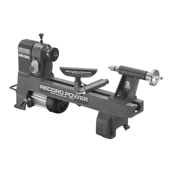
DML305 Cast Iron 6 Speed Midi Lathe
Version 3.2
January 2015
It is important to register your product as soon as possible in order to receive efficient after sales
support and be entitled to the full 5 year guarantee. Your statutory rights are not affected.
Kg
Always wear safety glasses when
using woodworking equipment.
To register this product please visit
www.recordpower.info
Please see back cover for contact details.
Important
i
For your safety read instructions carefully before
assembling or using this product.
Always read the instructions
provided before using
Save this manual for future reference.
woodworking equipment.
1
Advertisement
Table of Contents

Subscribe to Our Youtube Channel
Related Manuals for Record Power DML305


Summary of Contents for Record Power DML305
- Page 1 Original Instruction Manual DML305 Cast Iron 6 Speed Midi Lathe Version 3.2 January 2015 To register this product please visit www.recordpower.info It is important to register your product as soon as possible in order to receive efficient after sales support and be entitled to the full 5 year guarantee. Your statutory rights are not affected.
-
Page 2: Table Of Contents
Getting to Know Your Lathe Assembly Assembly of the DML305/A Leg Stand 10 Assembly of the Optional DML305/L Extension Support and DML305/E Bed Extension 11 Adjustments and Operations 12 Intended Use of the Lathe & Basic Woodturning Instructions 13 Dust Extraction 14 Troubleshooting 15 Electrical Connection &... -
Page 3: Explanation Of Symbols
1. Explanation of Symbols The symbols and their meanings shown below may be used throughout this manual. Please ensure that you take the appropriate action wherever the warnings are used. Mandatory Instructions Read and fully understand the instruction manual before attempting to use the machine. -
Page 4: General Health & Safety Guidance
2. General Health & Safety Guidance Ensure that you carefully read and fully understand the 6. The machine should be level and stable at all times instructions in this manual before assembly, installation and use • When using a leg stand or cabinet base that is designed to be fitted to of this product. - Page 5 2. General Health & Safety Guidance • If the work area is to be left unattended, all machinery should be switched additional support for a work piece that is longer or wider than the basic ‘OFF’ and isolated from the mains power supply. table, or to help feed, support, or pull the work piece.
-
Page 6: Additional Health & Safety Guidance For Woodturning Lathes
2. General Health & Safety Guidance the machine. 32. Have your machine repaired by a qualified person • This machine complies with the relevant safety rules and standards • A guard or other part that is damaged should be properly repaired appropriate to its type when used in accordance with these instructions or replaced by a qualified person unless otherwise indicated in this and with all of the standard safety guards and equipment in place. -
Page 7: Record Power Guarantee
Guarantee should be made directly to Record Power or its Authorised Distributor Record Power guarantees that for a period of 5 years from the date (for details of the Authorised Distributor in your country please see of purchase the components of qualifying Products (see clauses 1.2.1 your Product manual or check www.recordpower.info for details). -
Page 8: Specifications
5. Specifications Max bowl diameter: 305 mm Max between centres: 393 mm Max swing over bed: 305 mm Spindle speeds: 350, 670, 1025, 1500, 2225 & 3250 rpm Motor: 230 V / 50 Hz / 1/2 hp / 375 W Full load current: 2.6 A Tailstock spindle travel: 60 mm... -
Page 9: Getting To Know Your Lathe
7. Getting to Know Your Lathe 11 Tailstock 16 Tool holder Motor 4 prong drive centre Lifting handle Faceplate 12 Tailstock hand wheel 17 Tailstock locking lever Switch Tool rest 13 Lathe bed 14 Tool rest holder locking lever Hand wheel Tool rest holder Indexing assembly 10 Revolving centre... - Page 10 8. Assembly - cont. The nylon locking nut can now be tightened until the tool rest holder is held Fig.8.4 Tool rest holder firmly on the lathe bed but can slide freely along its length, Fig 8.4. Installing the Tool Rest to the Tool Rest Holder Clamp Loosen the locking handle and insert the tool rest into tool rest holder, adjust the height as required and tighten the locking handle, Fig.8.5.
- Page 11 Four mounting holes are easily accessible at the base of the lathe, Spindle wrench Fig.8.14. Drill holes in the work surface, using a 13 mm or 1/2” drill bit, following the measurements shown in Fig. 8.15. Note: Use of the DML305/A Leg Stand is recommended. Fig.8.13 Tool holder Pan head screw Fig.8.14...
- Page 12 9. Assembly of the Optional DML305/A Leg Stand Contents of the Package 1 Upright plinths x 2 2 Male cross brace 3 Female cross brace 4 M10 x 25 mm set screws x 2 5 M8 x 35 mm bolts, nuts and washers x 2...
- Page 13 9. Assembly of the Optional DML305/A Leg Stand - cont. 1. Attach the upright column to the base using two M10 x 80 mm bolts, Fig.9.1 ensuring that there is an M10 washer between each bolt and the upright column and another M10 washer between each M10 nut and the base, Fig.9.1.
-
Page 14: Assembly Of The Optional Dml305/L Extension Support And Dml305/E Bed Extension
10. Assembly of the Optional DML305/L Extension Support and DML305/E Bed Extension Contents of the DML305/L Extension Support Package 1 Upright plinth 2 Male cross brace 3 Female cross brace 4 M10 x 25mm set screws x 2 5 M8 x 35 mm bolts, nuts and washers x 2... - Page 15 10. Assembly of the Optional DML305/L Extension Support and DML305/E Bed Extension - cont Assembly of the DML305/L Extension Support Fig.10.1 Attach the upright column to the base using two M10 x 80 mm bolts, ensuring that there is an M10 washer between each bolt and the upright column and another M10 washer between each M10 nut and the base, Fig.10.1.
- Page 16 50 mm M10 bolts Using the hex wrench supplied, adjust the blind set screws on top of the optional DML305/L Extension Support bed extension to raise (turn clockwise) or lower (turn anti-clockwise) the extension until it is flush with the main bed of the lathe, Fig.10.9.
-
Page 17: Adjustments And Operations
11. Adjustments and Operations Adjusting the Tool Rest Tool rest Tool rest holder Fig.11.1 To move the tool rest across the lathe bed, loosen the locking lever by turning in an anti-clockwise direction, slide the tool rest base to the new position and tighten the locking lever in a clockwise direction. - Page 18 11. Adjustments and Operations - Cont. Fig.11.6 With the headstock cover open, loosen the locking arm. Raise the tension lever to release tension on the motor pulley and tighten the locking arm, see Fig. 11.7. Check speed and belt position chart inside access the cover to Clip determine the spindle speed required.
-
Page 19: Intended Use Of The Lathe & Basic Woodturning Instructions
12. Intended Use of the Lathe & Basic Woodturning Instructions Intended Use of the Lathe Fig.12.1 This lathe is designed for turning wood between centres or on the head- stock (using appropriate accessories), for sanding and applying finishes to wood. It is not to be used for any other purpose. Doing so will invalidate the warranty and may cause serious harm to the user. - Page 20 There are a wide variety of special- ised chisels and many complementary accessories available for Record Power lathes which enable a huge variety of work to be created. For further instructions on more advanced safe and effective...
-
Page 21: Dust Extraction
Record Power Extractors for 20 minutes every hour. 0.5 micron filtration Record Power offer a range of high quality dust extractors, we offer both drum and bag type extractors which filter down 0.5 micron providing protection from harmful fine dusts. All Record Power dust extractors & chip CX2000 Compact Chip Extractor collectors have 100 mm inlets and hoses. -
Page 22: Troubleshooting
14. Troubleshooting Warning: For your own safety, always turn off and unplug the machine before carrying out any troubleshooting. Problem Possible Cause Solution Motor will not start Machine not plugged in Plug the machine in Low voltage Check power supply to machine Loose connection Check all external connections Motor overheats... -
Page 23: Electrical Connection & Wiring Diagram
15. Electrical Connection & Wiring Diagram Machines supplied for use in the UK are fitted with a 3 pin plug conforming fitted with a fuse conforming to BS1362 appropriate to the rating of the to BS1363, fitted with a fuse conforming to BS1362 and appropriate to the machine. -
Page 24: Parts Diagram & List
16. Parts Diagram & List... - Page 25 16. Parts Diagram & List - cont. Part No. Description Part No. Description Wrench Collar Spur centre Retaining ring 12 mm Faceplate Cam bolt Spindle shaft Clamp disc Bearing 6005-2Z Lock nut M10 Ring retaining 47 mm Live centre Indexing gear Axle sleeve Headstock Bolt...
-
Page 26: Eu Declaration Of Conformity
EU Declaration of Conformity Cert No: EU / DML305 / 1 Record Power Ltd, Centenary House, 11 Midland Way, Barlborough Links, Chesterfield, Derbyshire S43 4XA declares that the machinery described:- 1. Type: Variable Speed Midi Lathe 2. Model No: DML305 3. - Page 28 Woodworking Machinery & Accessories United Kingdom Eire Australia New Zealand Record Power Ltd Record Power Ltd Tools 4 Industry Tools 4 Industry Centenary House, 11 Midland Way Centenary House, 11 Midland Way Po Box 3844 Po Box 276079 Barlborough Links, Chesterfield...
Need help?
Do you have a question about the DML305 and is the answer not in the manual?
Questions and answers