Honeywell Galaxy 2 Series Installation Manual
Hide thumbs
Also See for Galaxy 2 Series:
- Quick start manual ,
- Installation manual (21 pages) ,
- User manual (20 pages)
Table of Contents
Advertisement
Quick Links
Advertisement
Table of Contents

Related Manuals for Honeywell Galaxy 2 Series


Summary of Contents for Honeywell Galaxy 2 Series
-
Page 1: Installation Manual
Galaxy 2 Series Installation Manual Honeywell Security... -
Page 3: Table Of Contents
Galaxy 2 Series Installation Manual Table of Contents Contents SECTION 1: INTRODUCTION ..............1 Optional Peripherals ..................... 1 Features ........................2 RF ............................2 Groups ........................... 2 Dialler ............................. 2 SMS Text Messaging......................2 ProxKeypads ........................2 Remote Servicing ......................... 2 SECTION 2: QUICK GUIDE ................ - Page 4 Galaxy 2 Series Installation Manual Table of Contents Connecting the Galaxy 2 Series to the PSTN ............. 9 Private Branch Exchange (PBX) Approval ................ 9 REN and SEN Numbers...................... 10 SECTION 5: HARDWARE ................. 11 PCB Layout (2–44+) ..................... 11 PCB Layout (2–20) ....................
- Page 5 Galaxy 2 Series Installation Manual Table of Contents Mounting the Metal Enclosure Base................23 Peripherals - Installation, Wiring & Addressing..........24 Configuring ......................... 24 General ..........................24 Mk7 LCD Keypad/Keyprox ....................25 Keypad/Keyprox Installation ........................25 Mk7 Keypad/Keyprox Addressing ......................26 Adding a Mk7 Keypad/Keyprox to the System ..................
- Page 6 Galaxy 2 Series Installation Manual Table of Contents SECTION 6: GENERAL OPERATION ............40 Galaxy 2 Series Users ..................40 Users ............................ 40 Engineers ..........................40 General Menu Operation..................40 Full Setting .......................... 41 Part Setting .......................... 41 Night Setting ........................42 Cancelling the Setting .......................
- Page 7 Galaxy 2 Series Installation Manual Table of Contents Option 44 - Mobile Nos ..........................56 Option 47 - Remote Access ........................57 Option 48 - Level 3 Access ........................57 Menu 50 - Engineer 1 Options ..................58 Option 51 - Parameters ..........................58 Option 52 - Zones ............................
- Page 8 Galaxy 2 Series Installation Manual Table of Contents SECTION 16: COMPLIANCE AND APPROVALS........107 EN50131 Compliance....................... 107 Public Switched Telephone Network (PSTN) Approval ..........107 HONEYWELL SECURITY LIMITED WARRANTY ........108 Appendix A: Point ID Comms Triggers ..........A-1...
-
Page 9: Section 1: Introduction
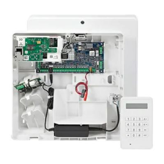
SECTION 1: INTRODUCTION The Galaxy 2 Series is a range of 12 zone intruder alarm control panel. There are 2 variants. The 2-44+ is the full function version which is expandable to 44 zones. The 2-20 is an entry level version which is expandable to 20 zones. -
Page 10: Features
Galaxy 2 Series Installation Manual Introduction (cont’d) RF Radio Receiver: This allows the control panel to receive signals from wire-free detectors and radio keyfobs. One radio receiver will allow the panel to assign wire-free detectors to any or all of the 44 detection zones. -
Page 11: Section 2: Quick Guide
Default Engineer code: 112233 Menu Access Operation/Navigation Only valid codes can access the Galaxy 2 Series menu options. Type the code then press ent to access the menu. Data entry, on both ECP and RS485 keypads, is via the 0-9 function keys and the *, # on the keypad. -
Page 12: How To Restore An Alarm
Galaxy 2 Series Installation Manual Quick Guide (cont’d) How to Restore an Alarm Alarms, faults and tampers will be restored provided: 1. The cause has cleared 2. An authorised user PIN code or anti-code has been entered. 3. The conditions have been viewed on the keypad display after steps 1 and 2 above. -
Page 13: Section 3: System Architecture
2-way Voice (2-44+ only Power RIO (4) P026 * Only the first expander can be used on the 2-20 8 zones Twisted pair screened cable Belden 8723 equivalent. Daisy chain configuration only. Wireless Receiver (2) Figure 1. Galaxy 2 Series System Configuration... -
Page 14: Section 4: System Wiring
Galaxy 2 Series Installation Manual System Wiring SECTION 4: SYSTEM WIRING General Information It is essential that this product is installed correctly, in particular with respect to a person’s safety and connec- tion to the mains electricity supply. This product is not suitable for installation, maintenance or connection by the user. -
Page 15: Zone And Data Cable Type
Illumination of the green power LED 2 indicates the presence of a.c. mains supply. The cover of the Galaxy 2 Series enclosure must be replaced whenever any connection to the BT master socket is completed to prevent exposure to potentially lethal voltages from the... -
Page 16: Equipment Electrical Rating
Galaxy 2 Series Installation Manual System Wiring (cont’d) Equipment Electrical Rating The control equipment is designed to operate on a mains supply of 230 Volts a.c. (230 V +10% -15%) at a frequency of 50 Hz. It is not suitable for other types of supply. The maximum current consumption in normal use is 200 mA. -
Page 17: Connecting The Galaxy 2 Series To The Pstn
Series, see Figure 3. Private Branch Exchange (PBX) Approval The Galaxy 2 Series may be used with some analogue PBX exchanges. The correct operation of the Galaxy 2 Series cannot be guaranteed under all possible conditions of connection to compatible PBXs. -
Page 18: Ren And Sen Numbers
Ringer Equivalence Number (REN) shown on each item of apparatus, ensuring that the sum of RENs is not more than four. The REN of the Galaxy 2 Series is one (1). Assume that all British Telecom equipment has a REN of one unless otherwise marked. -
Page 19: Section 5: Hardware
Galaxy 2 Series Installation Manual PCB Layout SECTION 5: HARDWARE PCB Layout (2–44+) LED2 Figure 4. Galaxy 2–44+ PCB Layout... -
Page 20: Pcb Layout (2-20)
Galaxy 2 Series Installation Manual Zones PCB Layout (2–20) 2-way header RS485 termination AC Power Input Battery BATT + PROG HEADER Extension Terminals BATT - Phone Output Power 12 Volt Phone Auxilliary LINE IN Line Output Input Trigger F1 (1 amp) -
Page 21: Zones
The Galaxy 2–44+ has 12 on-board zones expandable to 44 (RS485 bus) or 36 (ECP bus). The zones on the Galaxy 2 Series can function in one of three modes; Normal Closed, Double Balanced and U.S. End of line. Zone wiring for the three modes are illustrated in the following three Figures: Figure 6. -
Page 22: Wiring Zones
Wiring Zones The zones on Galaxy 2 Series panels are defaulted as double balanced. Each zone is 1 kΩ closed and 2 kΩ open. The transition from 1 to 2 kΩ generates an alarm condition. Refer to Table 2 for details of the zone resistance and resulting conditions. -
Page 23: Zone Addresses
Galaxy 2 Series Installation Manual Zone Addresses Zone Addresses Each zone on the Galaxy 2 Series has a 4-digit address. For example: 1004, 1058. The address is made up of three reference numbers as shown in the following figure: Example: 1004... -
Page 24: Outputs
Driver, before connecting a loudspeaker. Trigger Header The Trigger Header on the Galaxy 2 Series is a set of pins, which consists of programmable outputs for an external communication module. The connection is via an optional ribbon cable (Part No. A229). -
Page 25: Inputs
Galaxy 2 Series Installation Manual Trigger Header Inputs Line Fault: This input tells the panel that the communicator has a telephone line fault (active low). Reset: This input from the communicator resets the panel on a low to high signal (negative removed). -
Page 26: Rs485 Wiring Recommendations
4. The power supply in the Galaxy 2 Series control panel and remote power supplies must not be connected in parallel. 5. The 0V of all remote power supplies must be connected in common to the 0V of the Galaxy 2 Series control panel. -
Page 27: Ecp Bus (2-44+ Only)
PC. LED’S There are two LED’s on the Galaxy 2 Series PCB. Pulsing of the red LED1 indicates an active telecommuni- cations. Illumination of the green LED2 indicates the presence of AC mains supply. Audio Header (2–44+ Only) This is a 14-way shrouded header for audio connection. -
Page 28: Panel Mounting (Plastic Box)
Installation Kit The Galaxy 2 Series plastic box comes with an installation kit. It contains 13 zone links, a cable clamp with two self tapping screws, two M4 x 20mm lid screws, a tamper spring, battery connector leads and 24, 1K resistors. -
Page 29: Remove The Pcb
Fitting the Tamper Spring The Galaxy 2 Series plastic box enclosure is supplied without the tamper spring in place. The panel will not function without a Tamper. It is therefore the engineer’s responsibility to correctly attach the tamper spring. -
Page 30: Panel Mounting (Metal Box)
Installation Kit The Galaxy 2 Series metal box comes with an installation kit. It contains two No.8 x 12 mm self-tapping lid screws, 6160 Text Programming Overlay, two battery leads (one red and one black), 10 mm cable staple and 24, 1K resistors. -
Page 31: Removing And Replacing The Galaxy 2 Series Pcb
Galaxy 2 Series Installation Manual Panel Mounting (cont’d) Removing and Replacing the Galaxy 2 Series PCB NOTE: The metal box comes with the PCB installed. The PCB does not have to be removed to enable access to the keyhole mounting slot (see Figure 17). -
Page 32: Peripherals - Installation, Wiring & Addressing
Changes to peripheral addresses will only take effect when the peripheral is re-powered. General The following peripherals can be connected to the Galaxy 2 Series: RS485 Bus: Mk7 LCD Keypad/Keyprox; RIO; PSU; Wireless Receiver. NOTE: Up to four keypads (including keyprox) can be fitted to this line. Keypads/keyproxes must be wired in daisy chain configuration (see RS485 Wiring Configuration). -
Page 33: Mk7 Lcd Keypad/Keyprox
Peripherals (cont’d) Mk7 LCD Keypad/Keyprox The Mk7 keypad is a 16 character alpha-numeric keypad used to program and set the Galaxy 2 Series. The window display is spread over two lines. The Mk7 keyprox is a standard keypad with a proximity card reader combined into one housing. This allows dual function setting/unsetting ability from one station without the need for a separate card reader. -
Page 34: Mk7 Keypad/Keyprox Addressing
Galaxy 2 Series Installation Manual Peripherals (cont’d) 4. If you are using a wall-run cable for the keypad (A, B, +, -) position the cable behind the back plate in the cable channels provided. The cable can be run in from either the top or the bottom of the back plate. -
Page 35: Remote Input Output (Rio)
Galaxy 2 Series Installation Manual Remote Input Output (RIO) Galaxy RIO’s can be added to the RS485 Bus on the Galaxy 2 Series control panel. Each additional RIO expands the system by eight zones and four outputs. Outputs RS 485... -
Page 36: Configuring The Rio
(refer to Table 10). When an output is activated, the load is switched to the negative supply voltage (ground or 0 V) of the RIO. The current available through each output is 400 mA. The default functions and pull-up resistors of each RIO output, when connected to a Galaxy 2 Series are shown in the following Table: Output No. -
Page 37: Power Supply Unit
The Galaxy Power Supply Unit (PSU) consists of two modules, the Power Block and the Control Unit. The PSU can be connected to the Galaxy 2 Series control panel via the RS485 (AB) line. The PSU can be used in place of a standard RIO to overcome power problems that arise when the additional RIO is fitted distant to the control panel. -
Page 38: Installation Instructions
Galaxy 2 Series Installation Manual PSU (cont’d) Installation Instructions The installation and wiring must be performed by a competent engineer. The Galaxy Power Supply Unit must be connected to the a.c. mains supply (230/240 Va.c. 50Hz) via a fused connection outlet. The fuse in the mains outlet must not exceed 3A. -
Page 39: Battery
Galaxy 2 Series Installation Manual PSU (cont’d) Battery The minimum capacity battery to supply the PSU is 1x 7Ah. The maximum capacity battery to supply the PSU is 2 x 17Ah. Battery Test A battery test on full load is automatically performed once an hour and during the Engineer Mode exiting procedure. -
Page 40: Ecp Zone Expander (2-44+ Only)
Galaxy 2 Series Installation Manual ECP Zone Expander ECP Zone Expander (2–44+ Only) This is an expander for use on panels that use the ECP communication Bus. Up to three zone expanders can be fitted to the Galaxy 2–44+ panel. Each expander gives 8 extra hardwired zones and four programmable outputs. -
Page 41: Addressing The Ecp Zone Expander
Galaxy 2 Series Installation Manual ECP Zone Expander (cont’d) Addressing the ECP Zone Expander Select jumper addresses before powering up the zone expander. Available addresses are 2, 3, and 4. Refer to Table 11 for jumper settings. 8-Zone Expander 4-Zone Expander... -
Page 42: V2 Wireless Receiver
Wireless Receiver V2 Wireless Receiver Up to two receivers can be connected to the RS485 (AB) line. The V2 Wireless Receiver acts as an RF receiver for the Honeywell 868MHz transmitter range. Figure 25. V2 Wireless Receiver V2 Receiver Tamper Switch SW2 on the Receiver acts as a tamper if the tamper link LK1 is missing. -
Page 43: 6160 Keypad/Keyprox/Rfh (2-44+ Only)
Galaxy 2 Series Installation Manual 6160 Keypad 6160 Keypad/Keyprox/RFH (2–44+ Only) The 6160 keypad is an addressible, alphanumeric remote keypad for setting/unsetting the Galaxy 2–44+ control panel. It is also available as a combined keypad/keyprox unit (keypad with built-in proximity card reader). -
Page 44: Addressing The 6160 Keypad
Galaxy 2 Series Installation Manual 6160 Keypad (cont’d) Addressing the 6160 Keypad Keypad address (CON ADDR) needs to be from 0 to 3. To set the address: 1. Either repower the keypad or activate the keypad tamper switch. 2. Within 60 seconds of step 1, press and hold buttons 1 and 3 for five seconds. -
Page 45: 2-Way Audio (2-44+ Only)
Galaxy 2 Series Installation Manual 2-Way Audio 2-Way Audio (2–44+ Only) The system can support up to three TP500/800 speaker-mic devices via the audio header. To allow connec- tion via the Audio Header, an Audio Terminal Board must be fitted (part no. A233—2-way Audio Terminal Board). -
Page 46: Gsm Module (2-44+ Only)
Galaxy 2 Series Installation Manual GSM Module GSM Module (2–44+ Only) A Dedicated GSM telecommunication interface can be connected to the panel to allow an alternative commu- nication path to the PSTN telephone line. The GSM module is installed as follows. - Page 47 Galaxy 2 Series Installation Manual GSM Module (cont’d) 8. Slide the GSM antenna into the slot in the top of the enclosure and lock into place with the locking tab provided. 9. Refit the main panel PCB into the enclosure, connecting the miniature co-axial antenna cable between the GSM module and the antenna in the process.
-
Page 48: Section 6: General Operation
After this time, user authorisation will be required. General Menu Operation The Galaxy 2 Series provides various menu options for operating and modifying the functional performance of the system. To access any of the functions, a user must first log-in by typing a valid pin code. See SECTION 2, QUICK GUIDE, for details. -
Page 49: Full Setting
Galaxy 2 Series Installation Manual Setting Options To navigate around the menu and enter data, the keys are used as follows: 0-9: numeric data entry. ent: accepts current display or enters selected option. esc: escapes out of selected option. A> B<: scroll forward and backward in menu or selected option. -
Page 50: Night Setting
Galaxy 2 Series Installation Manual Setting Options (cont’d) Night Setting NIGHT SET NIGHT SET NIGHT SET NIGHT SET NIGHT SET Enter: User code and press B. Press 2 = Night Set This is identical to the Part Setting procedure, except the keypad display indicates that the system is being Night Set. -
Page 51: Restoring Alarms
Galaxy 2 Series Installation Manual Alarm Restore Restoring alarms Alarms, faults and tampers will be restored provided: 1. The cause has cleared 2. An authorised user PIN code or anti-code has been entered. 3. The conditions have been viewed on the keypad display after steps 1 and 2 above. -
Page 52: Setting And Unsetting With Keyfobs
Galaxy 2 Series Installation Manual Setting with Keyfobs Setting and Unsetting with Keyfobs The following information applies when a radio receiver is connected to the system. To Full Set the system (5804 Keyfob): Begin Full Unset/Cancel Set Procedure Press the ON button on the keyfob (Full setting will commence as per keypad procedure). -
Page 53: Setting And Unsetting With Keytags Or Cards
Galaxy 2 Series Installation Manual Setting with Keytags/Cards Setting and Unsetting with Keytags or Cards The following information applies to systems fitted with a keyprox. To Full Set the system (6160 keyprox): Hold keytag or card in front of prox symbol for ARMED three seconds. -
Page 54: Text Programming
Text Programming Certain functions on the Galaxy 2 Series can be set up with text descriptors or names. When one of these is edited the keypad will initially show the name that is currently programmed. The A and B keys can be used to move the edit cursor right and left in the name. -
Page 55: Additional Functions
Galaxy 2 Series Installation Manual Additional Functions Additional Functions Code Tampers When enabled (see Option 51, Parameter 14 = Lockouts), when 10 wrong codes are entered in succes- sion, the keypad is locked. The lockout lasts for two minutes. After a further 10 wrong code entries, a tamper is logged and a signal is given. -
Page 56: Section 7: Menu Options
Galaxy 2 Series Installation Manual Setting Options SECTION 7: MENU OPTIONS Menu 10 - Setting Options Option 11 - Omit Zones This option allows zones to be temporarily removed (omitted) from the system. Once a zone has been omitted it does not generate an alarm condition. The omit status of the zone can be toggled on and off using the # key. -
Page 57: Menu 20 - Display Options
Galaxy 2 Series Installation Manual Display Options Menu 20 - Display Options Option 21 - Zone Status This option shows the status of each zone on the system one at a time. The scroll keys scroll along the zone list. For each zone, the zone type and its open/close/tamper status are displayed. If the # key is pressed, the resistance reading for that zone is displayed, if hard-wired, or the last recorded signal strength if it is RF (from Wireless Receiver on RS485 line only). -
Page 58: Option 23 - System Version
This option shows the panel type and software version. Option 24 - Print NOTE: A serial printer must be connected to the program header on the Galaxy 2 Series PCB. This option allows the user to print out the event log. -
Page 59: Menu 30 - Test Options
Galaxy 2 Series Installation Manual Test Options Menu 30 - Test Options Option 31 - Walk Test Menu option 31 allows a selection of zones or a single zone to be put on walk test. NOTE: Zones programmed with the following functions remain active during the walk test: 24 hours, PA, PA silent, Fire, Tamper, Batt Fail, AC Fail, Assistance, Bell Fail. -
Page 60: Menu 40 - Modify Options
1 = Pin The PIN identifies each user to the Galaxy 2 Series panel and permits the user to operate the system. This option allows a PIN to be assigned to a user or an existing PIN to be modified. The PIN must be a four, five or six digit number that is unique to the system. -
Page 61: User Types
Galaxy 2 Series Installation Manual Modify Options (cont’d) 2 = Type This attribute shows the type of user and the level of access for each. There are four sub-options: 0 = Cleaner (L2) 1 = Users (L2) 2 = Manager (L2) -
Page 62: Adding Keyfobs
Galaxy 2 Series Installation Manual Modify Options (cont’d) 3 = Groups This attribute determines the system groups that the user has access to and operational control over. This attribute is only available when the groups option is enabled, see Option 63.1. -
Page 63: Adding Keytags Or Cards - Mk7 485 Keyprox Only
Galaxy 2 Series Installation Manual Modify Options (cont’d) Adding Keytags or Cards - Mk7 485 Keyprox only 1. Enter menu 42.1 = Users.Users. 2. Select a user. 3. Select option 6 = Prox Tags. 4. Press A & 1 together to self-learn keytag/card on to system. -
Page 64: Option 44 - Mobile Nos
44 - Mobile Nos Option 44 - Mobile Nos The Galaxy 2 Series can send SMS messages to users on up to three separate phone numbers to alert them of system events. This option allows users to set up or alter the mobile phone numbers and the types of messages sent. There... -
Page 65: Option 47 - Remote Access
Galaxy 2 Series Installation Manual 47 - Remote Access Option 47 - Remote Access 1 = Service This option allows a user to initiate a call to the remote service centre or authorise a call in from the remote servicing centre. On entering the menu, the user can select which communication device is used. -
Page 66: Menu 50 - Engineer 1 Options
Galaxy 2 Series Installation Manual 51 - Parameters Menu 50 - Engineer 1 Options Option 51 - Parameters This option allows the engineer to modify the settings for the system functions. Options can be selected using the A or B keys or by entering the two digit parameter number and pressing the ent key. The selected options can then be programmed by typing the new value directly or by using the A key to increase or the B key to decrease the values assigned to the parameter;... - Page 67 Galaxy 2 Series Installation Manual 51 - Parameters (cont’d) Parameter Values Defaults 01=Bell Time 01-30 minutes (1 minute intervals - defaults to 15) 15 minutes 02=Bell Delay 0=Off. 1=On - 10 min. 0 = Off 04=Exit Time 00 - 99 Seconds. 00=Infinite time/final contact.
- Page 68 Galaxy 2 Series Installation Manual 51 - Parameters (cont’d) 01 = Bell Time This is the amount of time that the sounders/bells activate after an alarm condition has occured. The duration of the output is programmable within the range 1-30 minutes; the default is 15. Assigning a value of 00 sets the Bell Time to one hour maximum.
- Page 69 Galaxy 2 Series Installation Manual 51 - Parameters (cont’d) 07 = Intruder Resets This parameter dictates what type of reset is required for a signalled intruder alarm. There are two settings: 0. User This setting allows any user programmed with the following user types: user, manager, master, to reset a full intruder alarm.
- Page 70 Galaxy 2 Series Installation Manual 51 - Parameters (cont’d) 12 = Banner This parameter has three settings: 1. Top line 2. Bottom line programmed as for SMS 3. Show on Set 0 = Off (Blank display when Set) 1 = On (Display normal banner when set) The Day Mode Banner display on keypads can be altered.
- Page 71 Galaxy 2 Series Installation Manual 51 - Parameters (cont’d) Keypad tamper lockout is indicated on the keypad display. After 20 attempts, a tamper is logged and an event is signalled. When option 2 or 3 are selected the same rules apply to wireless fobs and prox tags.
- Page 72 Galaxy 2 Series Installation Manual 51 - Parameters (cont’d) 3. RF Jam This option selects whether or not the system can be set while there is an RF Jam (interference condition) present. 4. TEL Line Fault When set to on a line fault can be detected by the panel.
- Page 73 This parameter has 3 options: 1. Zone Config The zones on the Galaxy 2 Series function as Normally Closed, Double Balanced, End of Line. This sets the configuration for all hardwire zones on the system, including expanders. See Section 5: Hardware—Zones, for wiring instructions for each configuration.
- Page 74 Galaxy 2 Series Installation Manual 51 - Parameters (cont’d) 2. End of Line This option defaults to (1) Double Balanced. 2. EOL Resistor This selects the resistor value for the end of line (EOL) resistor used in EOL double balance zone configura- tions.
- Page 75 Galaxy 2 Series Installation Manual 51 - Parameters (cont’d) 6. RF Check The RF Check is a means of warning the user that the system is unable to determine the status of the detector. There are two options: 0 = No This option disables the checking of the RF Stop Set (see Section 8, RF Stop Set).
- Page 76 Galaxy 2 Series Installation Manual 51 - Parameters (cont’d) 2 = Never Unset The keypad can never unset the system. Unsetting can only be performed by a keyfob, proximity tag or card. NOTE: If the panel becomes locked by accidental selection of this option, the panel can be force unset by the following procedure: Remove all power from the system.
-
Page 77: Option 52 - Zones
Galaxy 2 Series Installation Manual 52 - Zones 8. Exit ZN conf. 0 = Before Entry (default) 1 = Except Entry 9. Entry clears conf. This options selects whether a single (unconfirmed) alarm activation is remembered for the purposes of confir- mation, after an entry door is open. - Page 78 Galaxy 2 Series Installation Manual 52 - Zones (cont’d) 1 = Function This option allows the function of the zone to be selected. The zone can be assigned a different function for each set mode (full, part and night set) to allow maximum flexibility. For instance, the zone can be pro- grammed with the ‘Intruder’...
- Page 79 Galaxy 2 Series Installation Manual 52 - Zones (cont’d) 2 = Descriptor Each zone can be assigned with an alpha-numeric description of up to 16 characters (see Table 14, Zone Text Characters). The descriptor is assembled from the character set in this table. On selecting the Descriptor attribute, the currently assigned descriptor (blank by default) is displayed on the top line.
- Page 80 Galaxy 2 Series Installation Manual 52 - Zones (cont’d) 5 = RF Options These options allow the zone to be set up with a wireless detector. There are six options selectable with this attribute: 1. Serial number This allows the detector’s unique serial number to be entered by typing the number or by using the auto-learn function.
- Page 81 Galaxy 2 Series Installation Manual 52 - Zones (cont’d) 02 Exit Zones that protect the entry and exit routes are programmed as Exit. During the setting and unsetting proce- dures Exit zones have a non-alarm operation. If the Exit zone is activated while the system is set - without the unsetting of the group being initiated - an Intruder alarm condition is activated.
- Page 82 Galaxy 2 Series Installation Manual 52 - Zones (cont’d) The Push Set zone can be either 1kW going to 2kW or 2kW to 1kW - refer to Figure 8 (Keyswitch/ Terminator Zone Wiring) for wiring details. The first time that the Push Set is used to terminate the setting, the button will require to be pressed twice;...
- Page 83 Galaxy 2 Series Installation Manual 52 - Zones (cont’d) 17 Link This has no alarm function but can be used to activate links. 18 Spare The Spare function allows any zones that are not being used to be ignored by the system; the resistance readings from the circuit - including the tamper conditions - do not activate an alarm condition.
-
Page 84: Option 53 - Outputs
Galaxy 2 Series Installation Manual 53 - Outputs Option 53 - Outputs This option allows the operation of all the system outputs to be programmed. Outputs numbered 0001 to 0008 are the outputs from the trigger header. Outputs numbered 1001 to 1004 are the standard outputs on the main PCB. - Page 85 Galaxy 2 Series Installation Manual 53 - Outputs (cont’d) 05 Tamper (Latch) The Tamper output is activated whenever a circuit tamper or lid tamper occurs. The output is not subject to rearm: it latches on and remains active until a valid code, with the appropriate System Reset level, is entered.
- Page 86 Galaxy 2 Series Installation Manual 53 - Outputs (cont’d) 44 Abort (Latch) The ABORT output is activated when a valid code is entered to unset the system following a signalled intruder alarm. 45 Unset (Pulse) The Unset output is activated each time the system (or group) is unset.
-
Page 87: Option 56 - Comms
56 - Comms Option 56 - Comms The Communications option is used to control the Galaxy 2 Series system signalling and has five submenus broken down as follows: 1 = Telecoms; 5 = GSM; 6 = HW Priority; 7 = Parameters, 8 = 2-Way Voice Telecom/GSM These sub-sections set up the parameters for the built-in dialler modem and the GSM Module. - Page 88 Galaxy 2 Series Installation Manual 56 - Comms (cont’d) 01 Format The communicator provides three signalling formats: • DTMF • • Contact ID Once the format has been selected, the alarm and event triggers that the panel will transmit to the ARCs, may be programmed.
- Page 89 Galaxy 2 Series Installation Manual 56 - Comms (cont’d) 4 = Groups NOTE: The Groups attribute is only available if groups have been enabled on the system (refer to Option 63 = OPTIONS) and is also dependent upon the programmed output function for the channel.
- Page 90 PC loaded with suitable software or to a SIA compatible receiver. The SIA format is capable of transmitting over 70 different Galaxy 2 Series events (refer to Appendix A for further details). On selecting the SIA format, the keypad prompts for the required SIA level to be entered, there are 4 SIA levels available: •...
- Page 91 Galaxy 2 Series Installation Manual 56 - Comms (cont’d) 02 Telephone No.1 Telephone number 1 must be entered. This is the main telephone number that the alarms are signalled to. Up to 20 digits may be entered, including control modifiers.
-
Page 92: Dial Type
00 – 15. The following table shows the panel operation. s l l Table 25. Panel Operation If set to answer machine defeat (15), the Galaxy 2 Series only picks up the line if the download PC dials in, hanging up after one ring, then redials within 30 seconds. -
Page 93: Remote Access
Galaxy 2 Series Installation Manual 56 - Comms (cont’d) 10 = Line Fail This option has two settings: 0 = No When set to No there is no internal alarm or indication in the event of a telephone line fail condition. - Page 94 3 = Callback No. Remote servicing software requests the Galaxy 2 Series to call back the programmed telephone number. 4 = Downloader ID This option specifies an eight-digit ID number for panels communicating via the remote servicing software.
- Page 95 Galaxy 2 Series Installation Manual 56 - Comms (cont’d) Where SMS has been programmed to send via both the PSTN and GSM modules, the panel will always try and send using the GSM module. The PSTN module will be backup only.
- Page 96 Galaxy 2 Series Installation Manual 56 - Comms (cont’d) 5 = UCP Operation This option specifies the coding of UCP SMS operation both from the panel and the replies from the SMS message centre. 1 = Call Input This option sets part of the SMS operation message from the panel to the SMS message centre to be 01 (default value).
- Page 97 Galaxy 2 Series Installation Manual 56 - Comms (cont’d) 03 = Fire Delay This parameter determines the delay between the activation of a fire alarm and the signalling to an ARC. The Fire Delay is programmable within the range 00-60 seconds. The default is 00 seconds.
- Page 98 Galaxy 2 Series Installation Manual 56 - Comms (cont’d) 10 = STU Line Fail This parameter determines the line fail monitoring for the STU and has two options: 0 = No (default) 1 = Yes 11 = Remote Date This parameter allows the panel to be programmed to initiate a remote servicing call automatically on a pre- determined date and time.
-
Page 99: Option 57 - System Print
Galaxy 2 Series Installation Manual 57 - System Print Option 57 - System Print This option allows the engineer to print out the system programming and diagnostic information. On entering this option, the user is asked to confirm printing by pressing enter. Pressing enter at this point will print the system programming via the program header to a serial printer. -
Page 100: Menu 60 - Engineer 2 Options
The scroll keys can be used to view additional peripherals of that type if more than one is present. 1 = Keypads This gives the module type, address and the communication level between the Galaxy 2 series panel and the keypads. 2 = Zone RIO’s This gives the module type, address and the communication level between the Galaxy 2 Series panel and the zone RIO’s. -
Page 101: Option 62 - Full Test
For each peripheral, the following information is displayed where available: Table 27. Diagnostic Module Information The Galaxy 2 Series polls each module 32 times every second and reports the successful communications during this period as a percentage. This is calculated by the ratio of successful poll responses received from each module. -
Page 102: Option 63 - Options
Galaxy 2 Series Installation Manual 63 - Options Option 63 - Options .This menu has one sub-section: 1 = Groups There are three sub-options: 1 = Group Mode This option enables group mode. When enabled, each group on the system will behave as an independent area that can be separately set and unset. - Page 103 Galaxy 2 Series Installation Manual 63 - Options (cont’d) 3 = Comms Set Map This option selects which groups must be set before intruder communication can be enabled. This means either full set, night set or part set. The screen should appear as follows:...
-
Page 104: Section 8: Rf Hints And Tips
Galaxy 2 Series Installation Manual RF Hints & Tips SECTION 8: RF HINTS AND TIPS How to Install RF The system works with the current 5800 receivers on ECP and/or the V2 Wireless Receiver on RS485. A maximum of two RF receivers can be fitted on the ECP bus and two on the RS485 bus, to support up to 44 zones. -
Page 105: Section 9: Final Commissioning
Galaxy 2 Series Installation Manual Final Commissioning SECTION 9: FINAL COMMISSIONING Final system Test Before leaving the system to the user, or after any maintenance visits, it is important that the following checks are carried out. 1. Walk test on all zones using menu 31. -
Page 106: Section 10: Remote Servicing
Remote Servicing SECTION 10: REMOTE SERVICING The Galaxy 2 Series control panel can be remotely and/or locally serviced by a Personal computer (PC). This is accomplished when the Remote Servicing Pack is installed on the PC. Remote servicing is controlled in menu options 56.1 and 56.5. -
Page 107: Section 11: Flash Upgrade
A221. The kit comprises of a windows application which runs on a PC, and the flash programming lead which connects the Galaxy 2 Series PCB to the PC comm port. The actual software upgrade file for the Galaxy 2 Series will be supplied separately, as required by Honeywell Security. -
Page 108: Section 12: Printer Connection
SECTION 12: PRINTER CONNECTION The Galaxy 2 Series can print system detail directly to a serial printer. In order to do this a printer lead is required (part number A225) to connect between the program header on the Galaxy 2 Series PCB and the printer. -
Page 109: Section 13: Bell-Box Connections
Galaxy 2 Series Installation Manual Bell-Box Connections SECTION 13: BELL-BOX CONNECTIONS The terminal connections for various bell-box models are shown below: Lyntech Ltd. - 120 LED/120 lexon 2 Series Terminals BELL + 12V Bell box Terminals HOLD + STRB Elmdene Rapier 300, 4000, 5000, 6000; Prima 100, 200,300,400,500 600; Starlight 020... -
Page 110: Section 14: Event Log List
Galaxy 2 Series Installation Manual Event Log List SECTION 14: EVENT LOG LIST EVENT DESCRIPTION + AC AC zone activated - AC AC zone closed + AC> AC zone signalled - AC> AC zone closed signalled + CU AC Panel Mains fault... - Page 111 Galaxy 2 Series Installation Manual Event Log List (cont’d) EVENT DESCRIPTION + PA Panic zone activated - PA Panic zone closed + PA> Panic zone signalled - PA> Panic zone closed signalled PA RESET PA Reset + PA SIL Silent Panic zone activated...
- Page 112 Galaxy 2 Series Installation Manual Event Log List (cont’d) EVENT DESCRIPTION RESET System reset SOAK TST Zone soak test activation + OVERRDE Override of system faults TIM/DATE Time/Date adjusted - OMIT Zone unomitted UNSET System unset WALKTST- Walk test ended...
-
Page 113: Section 15: Specifications
Galaxy 2 Series Installation Manual Specifications SECTION 15: SPECIFICATIONS Panel Specifications 2-44+ 2-20 Physical Width: 300 mm Width: 300 mm Plastic Box-3 mm polycarb Height: 250 mm Height: 250 mm (with mains transformer and PCB installed) Depth: 100 mm Depth: 100 mm Weight: 1.7 kg... - Page 114 Galaxy 2 Series Installation Manual Specifications (cont’d) t i n Table 29. Peripheral current Consumption...
-
Page 115: Section 16: Compliance And Approvals
Galaxy 2 Series Installation Manual Approvals SECTION 16: COMPLIANCE AND APPROVALS The Galaxy 2 Series is compliant with the relevant parts of the following standards: • 99/05/EC R&TTE Directive • EN50130-5:1998 Alarm systems. Environmental test methods It is a condition of the product’s approval that the installation complies with the following:... -
Page 116: Honeywell Security Limited Warranty
Warranty HONEYWELL SECURITY LIMITED WARRANTY Honeywell Security, and its divisions, subsidiaries and affiliates (“Seller”), 165 Eileen Way, Syosset, New York, 11791, warrants its products to be in conformance with its own plans and specifications and to be free from defects in materials and workmanship under normal use and service for 24 months from the date stamp control on the product. -
Page 117: Appendix A: Point Id Comms Triggers
Galaxy 2 Series Installation Manual Comms Triggers Appendix A: Point ID Comms Triggers Menu Trigger Name Events Controlled CID Code SIA Code Panic Silent Panic Zone HA, HR Audible Panic Zone PA, PR Panic Hotkey Duress Code HA, HR Intruder... - Page 118 Galaxy 2 Series Installation Manual Honeywell Security 2 Redwood Crescent Peel Park Campus East Kilbride G74 5PA II1-0032 Rev 1 © Copyright Honeywell Security...
Need help?
Do you have a question about the Galaxy 2 Series and is the answer not in the manual?
Questions and answers