Table of Contents
Advertisement
Sep. 2001
Guitar Effects Processor
TABLE OF CONTENTS
TABLE OF CONTENTS ...................................................1
SPECIFICATIONS.............................................................2
LOCATION OF CONTROLS PARTS LIST ...................4
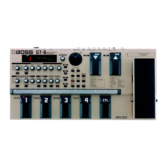
LOCATION OF CONTROLS ..........................................4
EXPLODED VIEW PARTS LIST .....................................6
EXPLODED VIEW ............................................................6
WIRING DIAGRAM.........................................................8
PARTS LIST........................................................................9
IDENTIFYING THE VERSION NUMBER ..................14
VIA MIDI..........................................................................14
BULK DUMP ...................................................................14
BULK LOAD ....................................................................14
Copyright © 2002 ROLAND CORPORATION
All rights reserved. No part of this publication may be reproduced in any form without the written permission
of ROLAND CORPORATION.
TEST MODE.....................................................................14
(FACTORY RESET).........................................................19
HOW TO UPDATE SYSTEM SOFTWARE .................19
BLOCK DIAGRAM.........................................................21
CIRCUIT BOARD (MAIN) ............................................22
CIRCUIT BOARD (MAIN) ............................................24
CIRCUIT DIAGRAM (MAIN 1/2) ...............................26
CIRCUIT DIAGRAM (MAIN 2/2) ...............................28
CIRCUIT BOARD (SW SHEET) ....................................30
CIRCUIT DIAGRAM (SW SHEET) ..............................32
ERROR MESSAGE ..........................................................34
17058013E0
SERVICE NOTES
First Edition
Issued by RJA
Printed in Japan (0800) (CM)
GT-6(T)
Advertisement
Table of Contents

Related Manuals for Roland GT-6


Summary of Contents for Roland GT-6
-
Page 1: Table Of Contents
TRANSMITTING / RECEIVING DATA VIA MIDI................14 BULK DUMP ..............14 BULK LOAD ..............14 Copyright © 2002 ROLAND CORPORATION All rights reserved. No part of this publication may be reproduced in any form without the written permission of ROLAND CORPORATION. Printed in Japan (0800) (CM) -
Page 2: Specifications
MIDI Implementation English (#17041119) FEEDBACK knob Foot Switch: FS-5U, FS-5L LEVEL knob Expression Pedal: EV-5 (Roland), FV-300L + PCS-33 (Roland) On/Off button Foot Switch Cable: PCS-31 (Roland) TAP button (1/4 inches Phone Plug (stereo) - 1/4 inches Phone Plug (mono) x 2) - Page 3 GT-6(T)
-
Page 4: Location Of Controls Parts List
Sep. 2001 GT-6(T) LOCATION OF CONTROLS LOCATION OF CONTROLS PARTS LIST fig.panel 15.17.19. 1.2. 15.16.19. 1.3. 11.12.13. 30.31.32.33. Part Code Part Name Q’ty G2477122 R-KNOB 34.35.37. 1.4. 28.29. 1.3. 14.19. F3279803 POTENTIOMETER RD901-40-125F- B54-11D (11 click) F3279804 POTENTIOMETER RD901-40-125F- B54-06D (6 click) -
Page 5: Exploded View Parts List
Sep. 2001 GT-6(T) EXPLODED VIEW PARTS LIST EXPLODED VIEW fig.jack [Parts] Part Code Part Name G2017152 TOP COVER G2017150 BOTTOM COVER G2237112 GUARD G2237113 GUARD PLATE G2567120 RUBBER SW G2567121 RUBBER SW ESCUTCHEON G2357120 FOOT H=5 G2567119 DISPLAY COVER 12499175... -
Page 6: Wiring Diagram
Sep. 2001 WIRING DIAGRAM fig.wiring WIRING 10P SW2 BOARD ASSY WIRING 8P WIRING 11P WIRING 7P RIBON 7P EXP BOARD CN11 WIRING 3P SW3 BOARD ASSY ASSY SW1 BOARD ASSY RIBON 3P SW4 BOARD ASSY CN10 ENC BOARD ASSY WIRING 2P MAIN BOARD ASSY... -
Page 7: Parts List
GT-6(T) PARTS LIST fig.part1e SAFETY PRECAUTIONS: SAFETY PRECAUTIONS: The parts marked have safety-related characteristics. Use only listed parts for replacement. The parts marked have PART NUMBER DESCRIPTION MODEL NUMBER safety-related characteristics. Use 22575241 Sharp Key C-20/50 only listed parts for replacement. - Page 8 Sep. 2001 01670745 TC74VHCT541AF IC (CMOS) IC18 on MB 02232834 TC7SH04F(TE85L) IC (CMOS) IC27,IC17 on MB 15249121 TC7W04F(TE12L) IC (CMOS) IC16 on MB 02340756 TC7WH32FU(TE12L) IC (CMOS) IC28 on MB 00458034 TC75S51F TE85R IC (OP AMP) IC25 on MB 15289106 M5238AFP-600C IC (JFET OP AMP) IC1 on MB...
- Page 9 GT-6(T) RESISTOR 01909734 RR0816P-682-D MTL.FILM RESISTOR R10,R53 on MB 02122623 RR0816R-104-D MTL.FILM RESISTOR R5,R44 on MB F5399911 0.68 (1/2W) RESISTOR R62 on MB F5399912 1.8K (F-RANK) RESISTOR R64 on MB F5399919 1M(F-RANK) RESISTOR R81 on MB F5399917 22 (1/2W) RESISTOR...
- Page 10 Sep. 2001 CONNECTOR F3439121 A2541WR2-2A16NP CONNECTOR 16P CN1 on MB F3439123 A2001WR2-3P CONNECTOR 3P CN4 on MB WIRING, CABLE G3467180 16P L=160MM LCD WIRING G3477146 3P L=40X5X5 MM P=2MM RIBBON CABLE CN5,CN6 on SW G3477156 7P P=2MM L=140MM RIBBON CABLE CN1,CN3 on SW G3467179 10P P=2MM L=120MM...
- Page 11 GT-6(T) ACCESSORIES (STANDARD) G6017297 OWNER’S MANUAL JAPANESE G6017298 OWNER’S MANUAL ENGLISH 01786212 AC ADAPTOR BRC-100T 01786223 AC ADAPTOR BRC-120T 01786234 AC ADAPTOR BRC-230T 01786245 AC ADAPTOR BRC-240AT 00905234 EURO CONVERTER PLUG ECP01-5A (PLUG for 230V) H5279511 READ ME FIRST JAPANESE/ENGLISH...
-
Page 12: Identifying The Version Number
(Refer to “Saving data” and “Loading data” for the user data storage DATA VIA MIDI procedures). Individual inspection items The GT-6 can use exclusive messages to set another GT-6 to the same settings, 1.DSP Check or to transmit its settings to a device such as a sequencer for storage. 2.Display The process of transmitting such data is called bulk dump, and the process of receiving such data is called bulk load. - Page 13 GT-6(T) DSP Check [2] The pedal switch group and expression switch inspection fig.LCD2 [BANK DOWN] -> [BANK UP] -> [EXP PEDAL SW] -> [CTL PEDAL] -> [PEDAL 4] -> [PEDAL 3] -> [PEDAL 2] -> [PEDAL 1] DSP (IC20) and DRAM (IC24) are automatically checked and their results [3] 7 seg LED displayed.
- Page 14 Sep. 2001 fig.LCD13 Confirm these three points. A) Using an oscilloscope, observe that a short wave is obtained from OUTPUT B) Since output mute is automatically made ‘On/Off’, make sure that it is on. C) Confirm that the level changes when the OUTPUT knob is turned. 2) Pressing further (maximum value) displays “***”...
- Page 15 GT-6(T) fig.10ext-2e fig.3 SEND (Signal source) (Cut off) RETURN OUTPUT (Rectangular waveform) Note: Check both L(MONO) and R. Also, when the OUTPUT jack is used for a single channel, the L and R signals will be internally mixed, therefore, empty plugs must be inserted in the R fig.4...
- Page 16 Sep. 2001 11. INPUT A/D fig.13noise-e fig.LCD22 INPUT Input a short wave, and observe the output waveform using an oscilloscope. OUTPUT Note: Check both L(MONO) and R. Also, when the OUTPUT jack is used for a single channel, the L and R signals (Connect noise meter) will be internally mixed, therefore, empty plugs must be inserted in the R channel for L(MONO) channel measurement and in the L(MONO) channel for...
-
Page 17: Restoring The Factory Settings (Factory Reset)
16. Factory load Notes fig.LCD29 Do not turn the GT-6 unit’s power off while writing the system software. The GT-6 will not operate because the system will not be properly written into the flash ROM. Notes After updating, execute “TEST:15.Calibrate EXP” and “TEST:16.Factory To overwrite the factory preset data, press the [WRITE] button three times. - Page 18 3-7.GT-6 : “Waiting SMF Data [GT6_07.mid]” -> MC-80 : GT6_07.mid play 3-8.GT-6 : “Waiting SMF Data [GT6_08.mid]” -> MC-80 : GT6_08.mid play After the GT-6 receives all the SMF data, it will display the checksum (4- digit number) of the system software on the LCD display, so confirm it.
-
Page 19: Block Diagram
GT-6(T) BLOCK DIAGRAM fig.block CN10 SW4 BOARD ASSY ENC BOARD ENCODER CARBON SW MIDI OUT IN EXP BOARD ASSY PEDAL VR JK11 SUB EXP PEDAL CN11 SUB CTL 1,2 SW 1 BOARD ASSY IC1b IC2b PANEL SW,LED INPUT IC2a IC21 CPU... -
Page 20: Circuit Board (Main)
Sep. 2001 GT-6(T) CIRCUIT BOARD (MAIN) fig.wiring View from components side... - Page 21 Sep. 2001 GT-6(T) CIRCUIT BOARD (MAIN) fig.sk949-c View from foil side...
-
Page 22: Circuit Diagram (Main 1/2)
Sep. 2001 GT-6(T) CIRCUIT DIAGRAM (MAIN 1/2) fig.sk961-c D 3. 3 MIDI D 3. 3 N.I.U. RA26 RA27 R67 120 D 3. 3 IC16C N.I.U. N.I.U. DIR "H" : A -> B TC7W04F DIR "L" : A <- B YKF51-5054 IC16D 2.2k... -
Page 23: Circuit Diagram (Main 2/2)
Sep. 2001 GT-6(T) CIRCUIT DIAGRAM (MAIN 2/2) fig.block 0.01 1.2K N.I.U. R3 18k C3 10P R4 12K(F) 1SS352 10/16 R5 100K(F) IC2A AK4552VT N.I.U 0.1(P) NJM2100M C150 MCLK SDTO ADDATA GUITAR IN IC1B 10/16 BCLK M5238FP LRCK LRCK C6 10P... -
Page 24: Circuit Board (Sw Sheet)
Sep. 2001 GT-6(T) CIRCUIT BOARD (SW SHEET) fig.block View from components side View from components side... -
Page 25: Circuit Diagram (Sw Sheet)
Sep. 2001 GT-6(T) CIRCUIT DIAGRAM (SW SHEET) fig.circuit-md BANK BANK EXP PEDAL FX "1" "2" "3" "4" "CTL" DOWN ON/OFF D 3. 3 D 3. 3 D 3. 3 D 3. 3 D 3. 3 EXP BOARD ASSY (6/6) D 3. 3 D 3. -
Page 26: Error Message
“LOW” is displayed when 2.7 V or lower. fig.EM-4 The memory backup battery inside the GT-6 has run down. (This message will appear when the power is turned on.) Replace the battery as soon as possible. For battery replacement, please contact a nearby Roland service center or your dealer.
Need help?
Do you have a question about the GT-6 and is the answer not in the manual?
Questions and answers