Table of Contents
Advertisement
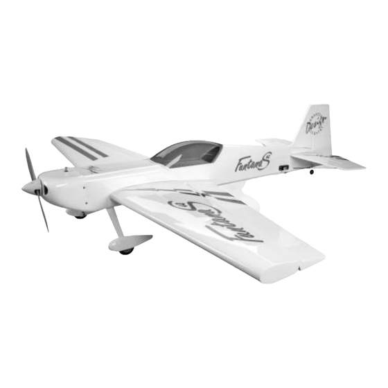
FuntanaS™ .40
Specifications
Wingspan: .............. 56 in (1422 mm)
Length: ................... 56 in (1441 mm)
Wing Area: ............ 714 sq in (46.1 sq dm)
The new FuntanaS™ .40 3D ARF was designed exclusively for Hangar 9
Sebastiano Silvestri. He based the FuntanaS on his highly successful KatanaS TOC design. The result is a
budget-friendly .40-size airplane with unlimited 3D performance.
The FuntanaS can do it all—harriers, torque rolls, blenders, and almost anything else you can dream up.
It's all possible, thanks to an extremely lightweight, all-wood airframe and big control surfaces that give
the FuntanaS a very impressive thrust to weight ratio and crisp control authority at any airspeed.
Sebastiano's signature UltraCote
pants complement the performance perfectly.
WE GET PEOPLE FLYING
ASSEMBLY MANUAL
Weight: ................... 4–5.5 lbs (1.8 Kg–2.5 Kg)
Radio: ..................... 4-channel w/5 servos
Engines: ................... 32–.46 2-stroke, .40–.72 4-stroke
®
trim scheme and factory painted parts such as the cowl and wheel
TM
®
®
by Italy's most famous 3D pilot,
Advertisement
Table of Contents

Related Manuals for Hangar 9 FuntanaS .40


Summary of Contents for Hangar 9 FuntanaS .40
-
Page 1: Specifications
Engines: ....32–.46 2-stroke, .40–.72 4-stroke ® The new FuntanaS™ .40 3D ARF was designed exclusively for Hangar 9 by Italy’s most famous 3D pilot, Sebastiano Silvestri. He based the FuntanaS on his highly successful KatanaS TOC design. The result is a budget-friendly .40-size airplane with unlimited 3D performance. -
Page 2: Table Of Contents
Table of Contents Table of Contents ............. . 2 Additional Required Equipment . -
Page 3: Additional Required Equipment
Contents of Kit Large Parts A. Fuse HAN1976 B. Wing HAN1977 C. Tail Set HAN1978 D. Canopy HAN1979 E. Cowl HAN1981 F. Wheel Pants HAN1982 G. Landing Gear HAN1983 Small Parts 1. Carbon Fiber Tail Support Rods HAN1980 Additional items sold separately Decal Set (not shown) HAN1984 Additional Required Equipment... -
Page 4: Additional Required Tools And Adhesives
Additional Required Tools and Adhesives Tools Other Required Items • Canopy Scissors • Epoxy brushes • Drill • Felt-tipped pen or pencil • Drill bit: 1/16”, 1/8” • Measuring device (e.g. ruler, tape measure) • Flat blade screwdriver • Mixing sticks for epoxy •... -
Page 5: Before Starting Assembly
Before Starting Assembly Before beginning the assembly of the FuntanaS™, remove each part from its bag for inspection. Closely inspect the fuselage, wing panels, rudder, and stabilizer for damage. If you find any damaged or missing parts, contact the place of purchase. If you find any wrinkles in the covering, use a heat gun or covering iron to remove them. -
Page 6: Section 1: Attaching The Wing To The Fuselage
Section 1: Attaching the Wing to the Fuselage Required Parts Step 2 • Wing • Fuselage Glue the dowels into the wing using 6-minute epoxy. • 1/4-20 x 2" nylon bolt Make sure there is around 1/2" of the dowel exposed. •... -
Page 7: Section 2: Installing The Horizontal Stabilizer
Section 2: Installing the Horizontal Stabilizer Required Parts Step 2 • Wing • Fuselage Check the distance from each stab tip to each wing • Horizontal stabilizer • Elevator joiner wire tip. Remember to measure right-to-right, left-to-left. It won’t work the other way around. These measurements •... - Page 8 Section 2: Installing the Horizontal Stabilizer Step 4 Step 6 Use a felt-tipped pen to trace the outline of the Place the elevator joiner wire into the slot for the stab. fuselage on the stab. Reposition the stab into the fuselage. It may be necessary to trim the opening at the rear to allow for clearance for the joiner wire.
- Page 9 Section 2: Installing the Horizontal Stabilizer Step 8 Step 10 Mark the location for the carbon fiber tail support Mark the bottom of the stab using a felt-tipped pen. rods. They will be positioned 2 " below the stab, The mark will be 1 "...
-
Page 10: Section 3: Installing The Vertical Stabilizer
Section 2: Installing the Horizontal Stabilizer Step 12 Carefully cut a notch into the stab along the line drawn. The goal is to have the end of the carbon rod rest in the slot. The notch will be roughly 3/32”–1/8” deep. Photo for Step 12 Step 13 Roughen up about 1/4"... - Page 11 Section 3: Installing the Vertical Stabilizer Step 2 Step 4 Check the alignment between the fin and stab. The Remove the covering 1/16" below the line drawn in fin must be 90 degrees to the stab to be in alignment. the last step.
-
Page 12: Section 4: Installing The Ailerons
Section 3: Installing the Vertical Stabilizer Step 6 Step 7 Use a sharp hobby knife to remove the covering from Mix 1/2 ounce of 30-minute epoxy. Apply the epoxy between the lines drawn in the last step. to the tab on the fin and to the area on the top of the fuselage where the covering was removed. - Page 13 Section 4: Installing the Ailerons Step 2 Step 4 Place the hinges in the precut slots in the aileron (or Use a ruler to align the end of the aileron to the wing. wing if you prefer). The T-pin will rest against the edge Also check the gap between the wing and aileron at when installed correctly.
-
Page 14: Section 5: Installing The Elevators
Section 4: Installing the Ailerons Step 5 Remove the T-Pins and apply thin CA to each hinge. Make sure the hinge is fully saturated with CA. Use a paper towel and CA remover/debonder to clean up any excess CA from the wing and/or aileron. Photo for Step 6 Step 7 Move the aileron up and down several times to work... - Page 15 Section 5: Installing the Elevators Step 3 Step 6 Slide the elevator and stab together. Remember to Remove the elevators from the stabilizer. Roughen insert the joiner wire into the elevator before the joiner wire using medium sandpaper. Mix starting the hinges. 1/2 ounce of 30-minute epoxy and apply it to the groove and hole in one elevator half.
-
Page 16: Section 6: Installing The Tail Wheel
Section 5: Installing the Elevators Step 8 Once the CA and epoxy has fully cured, give the elevator and stab the tug test to make sure the hinges are well glued. Flex the elevators a few times to break in the hinges. Section 6: Installing the Tail Wheel Required Parts Step 1... - Page 17 Section 6: Installing the Tail Wheel Step 2 Cut a groove from the hole to the bottom of the rudder. This is necessary to provide clearance for the tail wheel bearing. Photo for Step 4 Step 5 Test fit the tail wheel bearing into the slot. Make the slot large enough that the bushing will fit without forcing the wood apart.
-
Page 18: Section 7: Installing The Rudder
Section 7: Installing the Rudder Required Parts Step 3 • Fuselage assembly • Rudder Place the rudder in its location on the fuselage. You • CA hinge (3) may notice that there isn’t a slot cut into the fuselage for the bottom hinge. Use a felt-tipped marker to Required Tools and Adhesives indicate the location for the hinge. - Page 19 Section 7: Installing the Rudder Step 5 Step 7 Test fit the rudder to the fuselage. Make sure the tail Check to make sure the rudder moves freely. It should gear wire goes into the rudder, and that the rudder not rub against the fin at the tip.
-
Page 20: Section 8: Engine Installation
Section 8: Engine Installation Required Parts • Fuselage assembly • Engine mount (2) • 6-32 x 3/4" screw (4) • #6 x 5/8" socket head sheet metal screw (4) Required Tools and Adhesives • Drill • Drill Bit: 3/32" • Pliers •... -
Page 21: Section 9: Throttle Pushrod Installation
Section 8: Engine Installation Cool Tip: Use a drill press for the best results. Cool Tip: Apply a little bar soap to the threads This makes holes perfectly perpendicular of the screws to make them thread easier into (square) to the mount. the mount. -
Page 22: Section 10: Fuel Tank Assembly
Section 9: Throttle Pushrod Installation Step 2 Step 3 Test fit the throttle pushrod tube through the firewall Trim the throttle pushrod tube so it extends 1" onto and into the fuselage. Once satisfied with the fit, the servo tray. roughen the tube using medium sandpaper. - Page 23 Section 10: Fuel Tank Assembly Step 3 Step 6 Slide the smaller cap over the tube on the smaller end Locate the short piece of silicone fuel tubing and the of the rubber stopper. This end will be inserted into fuel tank clunk.
-
Page 24: Section 11: Fuel Tank Installation
Section 10: Fuel Tank Assembly Important: Be sure to differentiate between Step 8 the vent and fuel pickup tube. Once the tank is Tighten the M3 x 20 screw carefully—do not over mounted inside the fuselage, it will be difficult tighten. -
Page 25: Section 12: Electric Motor Installation
Section 11: Fuel Tank Installation Cool Tip: Make sure the rear support Step 3 brace will not interfere with the installation Install the fuel tank into the fuselage. Make any of the wing. necessary supports to keep the tank from moving during flight. -
Page 26: Section 13: Cowling Installation
Section 12: Electric Motor Installation Step 5 Install the batteries as shown. Use hook and loop material to keep the batteries from moving during flight.. Section 13: Cowling Installation Required Parts Step 2 • Fuselage assembly • Cowling Remove the engine. Position the cowl onto the •... - Page 27 Section 13: Cowling Installation Step 3 Step 6 Remove the cowl and remove the necessary material Enlarge the holes drilled in the cowling using a to fit the cowl over the engine. Install the engine back 1/8” drill bit. onto the firewall, and test fit the cowl over the engine. Step 7 Cool Tip: Start by removing only a little Make any cut outs in the cowling to clear items such...
-
Page 28: Section 14: Landing Gear Installation
Section 14: Landing Gear Installation Required Parts • Landing gear • 1" tail wheel • 2 " wheel (2) • 4-40 blind nut (2) • Fuselage assembly • 6-32 x 1/2" screw (2) • Wheel pant (left and right) • 5/32” x 1 "... - Page 29 Section 14: Landing Gear Installation Step 4 Step 7 Drill the location for the pant screw using a Attach the wheel to the axle using two wheel collars 5/32" drill bit. and set screws. The exact position of the wheel will be determined after the wheel pant is installed.
-
Page 30: Section 15: Radio Installation
Section 14: Landing Gear Installation Step 9 Step 11 Position the wheel so it is centered in the wheel Attach the tail wheel using a 5/32" wheel collar. pant. Tighten the collars once the wheel has been positioned. Step 10 Repeat Steps 2 through 9 for the other wheel pant. - Page 31 Section 15: Radio Installation Cool Tip: Place a drop of thin CA onto each Step 3 screw hole to harden the wood around the Mark the locations for the servos screws using a hole. Allow the CA to fully cure before felt-tipped pen.
- Page 32 Section 15: Radio Installation Step 7 Step 10 Temporarily install the aileron servo and mark Attach a 9" servo extension to the aileron servo. Tie the locations for the servos screws using a the string onto the servo extension. Gently pull the felt-tipped pen.
- Page 33 Section 15: Radio Installation Step 13 Step 14 Wrap the receiver and receiver battery in protective Temporarily mount the receiver and battery into the foam to prevent damage that may be cause by fuselage. It may be necessary to relocate the battery engine vibration.
-
Page 34: Section 16: Linkage Installation
Section 16: Linkage Installation Required Parts Step 3 • Wing assembly • Nylon clevis (5) Position the control horn on the elevator so the • Clevis retainer (5) • Fuselage assembly horn aligns with the hinge line of the elevator. Mark the position for the mounting holes using a •... - Page 35 Section 16: Linkage Installation Step 5 Step 7 Place 2-3 drops of thin CA into the hole to harden Center the elevator servo electronically using the the wood. Repeat this for each of the three holes. radio system. Install a servo arm onto the elevator servo.
- Page 36 Section 16: Linkage Installation Step 9 Step 12 Cut the wire 1/2” above the bend. Slide a clevis retainer onto a nylon clevis. Thread a clevis onto a 7-7/8” wire a minimum of 10 turns. Step 13 Remove the back plate from a control horn using side cutters or a sharp hobby knife.
- Page 37 Section 16: Linkage Installation Step Step 18 Install one of the #2 x 3/4" screws in a hole drilled, Center the aileron servo electronically using the radio then remove it. Place 2-3 drops of thin CA into the system. Install a servo arm onto the aileron servo. hole to harden the wood.
- Page 38 Section 16: Linkage Installation Step 21 Step 26 Repeat Steps 12 through 20 for the other aileron Make a Z-bend at the mark made in the last step. servo. Remove the clevis and slide the pushrod into the pushrod tube from the firewall. Connect the pushrod Step 22 to the throttle arm.
-
Page 39: Section 17: Canopy And Decal Installation
Section 17: Canopy and Decal Installation Required Parts Step 3 • Fuselage assembly • Canopy Lightly sand the inside edge of the canopy and slightly inside the line drawn on the hatch using Required Tools and Adhesives medium sandpaper. • Canopy glue (RC-56) • Sandpaper (medium grit) Finally, the fun part of building your model. -
Page 40: Adjusting The Engine
Control Throws and Center of Gravity Recommended CG Location The following control throws offer a good place to start with your first flights. We recommend only one rate An important part of preparing the aircraft for flight is setting for the FuntanaS. As you become more familiar properly balancing the model. -
Page 41: 2003 Official Ama National Model Aircraft Safety Code
2003 Official AMA National Model Aircraft Safety Code Effective January 1, 2003 Model Flying MUST be in accordance with this Code in order for AMA Liability Protection to apply. GENERAL 7) I will not operate models with pyrotechnics (any device that explodes, burns, or propels a projectile of any kind) 1) I will not fly my model aircraft in sanctioned events, air including, but not limited to, rockets, explosive bombs... - Page 42 2003 Official AMA National Model Aircraft Safety Code Continued 4) I will operate my model using only radio control Organized RC Racing Event frequencies currently allowed by the Federal 10) An RC racing event, whether or not an AMA Rule Communications Commission.
- Page 43 If you're looking for a 4-stroke to power your airplane, you'll want to check out Saito's latest release, Saito's new .72 4- stroke. It's the lightest weight engine in this 4-cycle displacement category. The .72 features an all-new crankcase with the same mounting dimensions as the Saito .56.
- Page 44 ® WE GET PEOPLE FLYING © 2003, Horizon Hobby, Inc. 4105 Fieldstone Road Champaign, Illinois 61822 (217) 355-9511 www.horizonhobby.com #5864...
Need help?
Do you have a question about the FuntanaS .40 and is the answer not in the manual?
Questions and answers