Russound CAA66 Installation Manual
Multisource multiroom audio controller/amplifier
Hide thumbs
Also See for CAA66:
- Specification (2 pages) ,
- Installation manual (52 pages) ,
- Manual (41 pages)
Table of Contents
Advertisement
Advertisement
Table of Contents

Related Manuals for Russound CAA66


Summary of Contents for Russound CAA66
- Page 2 CAA66 Multisource Multiroom Audio Controller/Amplifier Installation Manual...
-
Page 3: Important Safeguards
B. Objects have fallen, liquid has been spilled into the appliance; or appliance. C. The appliance has been exposed to rain; or If you have any questions please call Russound Inc. at 1-800-638-8055 or 603-659-5170. D.The appliance does not appear to operate normally; or Safety Instructions: E. -
Page 4: Table Of Contents
System Installation Considerations..................13 Connection Tips ........................13 Wiring Instructions Keypad Wiring........................14 Speaker Wiring .........................14 Component Guide CAA66 Controller Front Panel Removal ................15 CAA66 Controller Rear Panel .....................16 KP6 Keypad Update Port ....................17 KP6 Keypad Rear Panel ....................18 Keypad Installation KP6 Keypad Installation .....................18 Making Connections Keypad Port Connections....................19... - Page 5 TABLE OF CONTENTS Common IR Input Connection .....................22 Speaker Connections ......................23 Zone Fixed/Variable Audio Output ..................24 12VDC Mute Trigger In/Trigger Out ..................25 Controller Link In/Out ......................26 RS-232 Interface .......................27 Initial Hardware Install Test ....................28 Programming Programming Center ......................29 Controller Setup Mode Controller ID .......................30 Number of Sources.....................31 Factory Initialization.....................32...
-
Page 6: User Section Product Introduction
The CAA66 caters to homeowners who want more control over their multiroom systems with The CAA66 kit ships with a remote control such capabilities as infrared (IR) tools to manage (SRC1) and elegant keypads (KPL or KP6 mod- the system from anywhere in the house. -
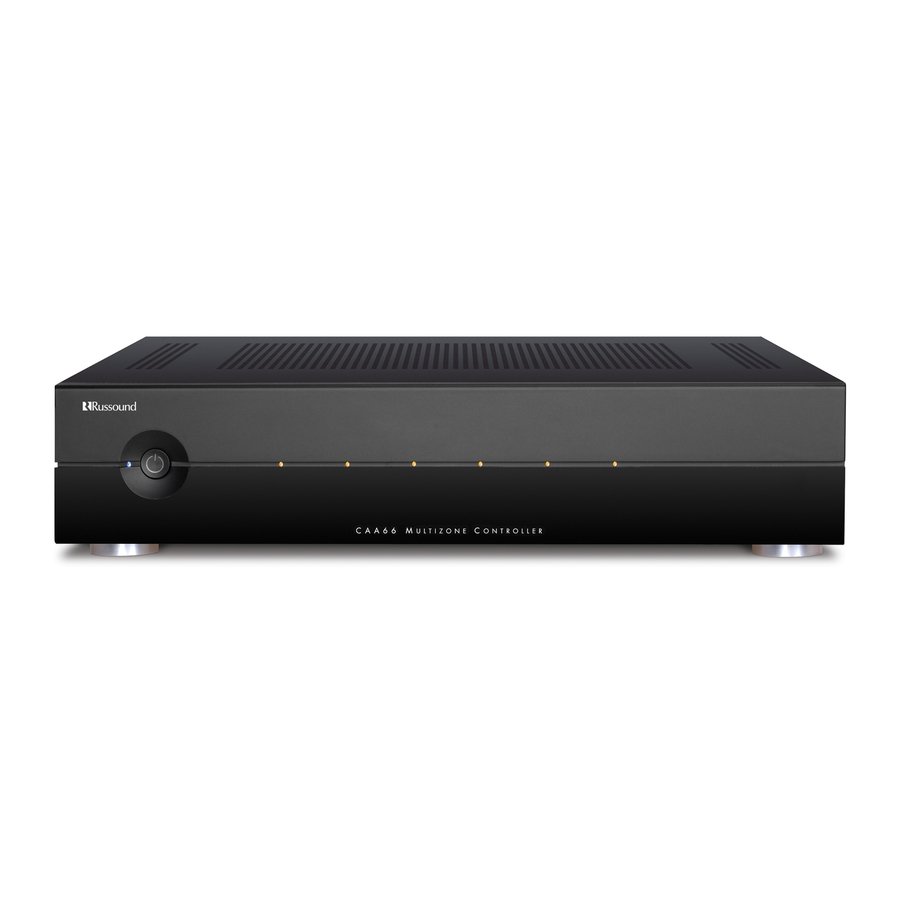
Page 7: Component Guide
COMPONENT GUIDE CAA66 FRONT PANEL The CAA66 front panel consists of a split molded “power on” indicator to the left which illuminates when piece with a removable bottom half. This bottom piece the unit is on. The six zone LEDs light up amber when hides the Programming Center buttons. -
Page 8: Kp6 Keypad
COMPONENT GUIDE KP6 KEYPAD AM/FM CABLE SERVER1 Source KP6 Keypad SOURCE NAME - Six clear windows with replaceable source name labels. Current source selected is backlit amber. VOLUME UP - Raises the volume for the room/adjusts User Menu options. VOLUME DOWN - Lowers the volume for the room/adjusts User Menu options. POWER - Turns zone ON or OFF when pressed once. -
Page 9: Kpl Keypad
COMPONENT GUIDE KPL KEYPAD Source KPL Keypad LCD PANEL - 5-character amber backlit display shows source name, volume and zone status. VOLUME UP - Raises the volume for the room/adjust User Menu options. VOLUME DOWN - Lowers the volume for the room/adjust User Menu options. POWER - Turns zone ON or OFF when pressed once. -
Page 10: Kpsc Keypad
COMPONENT GUIDE KPSC KEYPAD KPSC Source Control Keypad The KPSC keypad connects to a KP6 or KPL key- A second press of the Numeric button sends a pad to add source control and numeric capabili- Suffix command of “Enter” and puts the keypad ty. -
Page 11: Src1 Remote Control
COMPONENT GUIDE SRC1 SYSTEM REMOTE CONTROL POWER - Turns on or off selected zone. NUMERIC INPUT - Number buttons for direct input of frequency, channel, etc. VOLUME UP/DOWN - Raises or lowers the vol- ume in the zone. MUTE - Mutes/unmutes zone audio output. INFO - Displays current channel and program information. -
Page 12: Operation
OPERATION USER OPTIONS SETTINGS KP6 Keypad User Options Mode Operation Source window blinks to indicate the option that is ready for adjustment Source 1 Source 2 Source 3 Source 4 Source 5 Source 6 Bass Treble AM/FM Balance CABLE SERVER1 Turn On Volume Option... -
Page 13: Kpl User Options Mode
OPERATION USER OPTIONS SETTINGS KPL Keypad User Options Mode Operation Bass Press and Press Volume hold Source Up or Down Source button to buttons to enter or exit adjust setting User Options Mode Press Source button to select option Blue LED will blink to indicate Loudness is ready for adjustment KPL User Options Mode... -
Page 14: Getting Started
• 1 (one) SRC1 System Remote Control Connection Tips • 6 (six) 845.1 Micro Emitters • It is recommended that the CAA66 and the source equipment be plugged into a dedicated Tools needed for installation: 20-amp circuit with an isolated ground. A power •... -
Page 15: Wiring Instructions
• Label wires with keypad and room location. CAT-5 WIRE COLOR TYPE This simplifies CAA66 hook-up once the key- Brown..... +12V pads and speakers are installed. -
Page 16: Component Guide
Controller Front Panel Removal Front Panel Removal this may require moving it until the front edge hangs The CAA66 front panel removable bottom half hides clear of the shelf. the Programming Center. It is important to follow the proper removal process to remove the panel without Place a flat screwdriver blade in the bottom slot on damage. -
Page 17: Caa66 Controller Rear Panel
COMMON IR OUTPUT - Output jack passes all IR signals from all keypads. SOURCE IR OUTPUTS - Six source-specific IR Output jacks allow IR control of source equipment. SOURCE INPUTS - Six pair of Audio Line Level input connections for CAA66 source components. -
Page 18: Kp6 Keypad Update Port
Document Center on www.russound.com. Look in the “Firmware Software Updates” section under CAA System product type. The Advanced Programming Cable is avail- able from Russound, Part #2500- 521065. KP6 Front View KP6 Top View Jumpered pins... -
Page 19: Kp6 Keypad Rear Panel
INSTALLER COMPONENT GUIDE Keypad Rear Panel and Installation CAT-5 to KP6/KPL Connection if the terminations deviate from the The KP6/KPL keypad uses a 110- required connection order. punchdown terminal on the back Take care when using an impact 110 panel to provide simple installation punchdown tool, as this may over- and a strong connection for CAT-5 spread the contact points. -
Page 20: Making Connections
The Keypad Ports are located on the back of If using more than one keypad in a zone, use an the CAA66 in the top left of center. Connections SA-ZX3 System Keypad Splitter (optional). The at the Keypad Ports are made with RJ45 con- SA-ZX3 supports up to three keypads per zone nectors using T568A CAT-5 wire configuration. -
Page 21: Source Audio Input Connections
IR, the source must be selected at the Each source component has a designated IR keypad receiving the command. port on the back of the CAA66. This IR port is directly above the Source Audio Input Connections. RCA Cable... -
Page 22: Rnet Source Audio Connections
Using quality RCA signal cables, connect the Left and Right Audio outputs from each RNET source to the corresponding inputs on the CAA66 controller. Label each cable with the name of the selected source and the Source Audio input number located on the CAA66. -
Page 23: Common Ir Input Connection
MAKING CONNECTIONS Common IR Connection Common IR Connections The Common IR jack on the rear of the CAA66 The Russound 845.1 single IR emitter is recom- allows control of any source equipment without mended, or use an IR connecting block such as that source being selected on the keypad. -
Page 24: Speaker Connections
INSTALLER MAKING CONNECTIONS Speaker Connections The speakers are connected to the CAA66 using WHITE -- L+ (left channel positive) modular snap connectors. Each of these color- GREEN -- L- (left channel negative) coded connectors is designated for the speaker set of a particular amplified zone. To avoid con-... -
Page 25: Zone Fixed/Variable Audio Output
MAKING CONNECTIONS Zone Fixed/Variable Audio Outputs Zone Fixed/Variable Audio Output The CAA66 has two line Audio outputs, on Zone The fixed or variable audio outputs can be used 1 and Zone 2. Each of these zone audio output if additional amplification is desired (e.g., connections features a stereo line out RCA con- Russound R235LS two-channel amplifier). -
Page 26: 12Vdc Mute Trigger In/Trigger Out
This allows for the connection of an external pag- sleeve is negative (-). The System Trigger Out ing or muting device. Note: The CAA66 will not supplies 12VDC when the first keypad is turned accept a paging audio input; however, if used on. -
Page 27: Controller Link In/Out
CAT-5 patch cable from Out ports, each controller must have a unique the Link Out of the master CAA66 and into the Controller ID prior to being connected through Link In of the next controller. Along with data sig- the Link In and Out ports. -
Page 28: Rs-232 Interface
Center at www.russound.com . Look for the troller. The RS-232 com port is located on the Technical Documents under CAA System. back of the CAA66 and uses a DB-9 cable con- nection. For firmware updates, be sure the CPU Update switch next to the the RS232 interface is set in the “Update”... -
Page 29: Initial Hardware Install Test
1. Check the source to see that it is operating properly. 2. Check the RCA Audio cable connections from the source to the Source #1 Input on the CAA66. 3. Check the speaker connections and verify that they are correct and are connected to the Zone #1 speaker outputs. -
Page 30: Programming Center
IR/Learn) and are accessed with a press of the Setup through the Programming Center, located on the front button. of the CAA66 behind the removable lower panel. The The SRC1 system remote control is used to enter LEDs are dual purpose with different colors to indicate information during the setup procedures, and the LEDs different modes. -
Page 31: Controller Id
INSTALLER PROGRAMMING OVERVIEW... -
Page 32: Number Of Sources
INSTALLER PROGRAMMING OVERVIEW... -
Page 33: Factory Initialization
INSTALLER PROGRAMMING OVERVIEW... -
Page 34: Controller Setup Flow Chart
INSTALLER PROGRAMMING OVERVIEW... -
Page 35: Source Setup
INSTALLER PROGRAMMING OVERVIEW... -
Page 36: Command Type Options Rnet Sources
INSTALLER PROGRAMMING OVERVIEW... -
Page 37: Uei Library
INSTALLER PROGRAMMING OVERVIEW... -
Page 38: Learned Ir
INSTALLER PROGRAMMING OVERVIEW... -
Page 39: Invalid Code
INSTALLER PROGRAMMING OVERVIEW... -
Page 40: Clear Code
INSTALLER PROGRAMMING OVERVIEW... -
Page 41: Source Setup Flow Chart
INSTALLER CAA66 SOURCE SETUP FLOW CHART... -
Page 42: Kpl Setup Flow Chart
KPL SETUP AND DIAGNOSTIC MENUS KPL Setup Menu KPL Setup Menu The KPL Setup menu is used to choose source names, check the version number and perform a Factory Initialization of the CAA66 FACT INIT controller. The menu is outlined in SOURCE SOURCE SOURCE Procedure the diagram to the right. -
Page 43: Source Names
REFERENCE SOURCE NAMES - KPL KEYPAD Description Description 5-Character Description 5-Character Display 5-Character Display Display Auxiliary DSS Receiver MSvr1 Media Server 1 Aux 1 Auxiliary 1 DSS 1 DSS 1 MSvr2 Media Server 2 Aux 2 Auxiliary 2 DSS 2 DSS 2 MSvr3 Media Server 3... - Page 44 REFERENCE SOURCE NAMES - KPL/KP6 KEYPADS KP6 Labels Description Description 5-Character Display 5-Character Display Src 4 Source 4 XM 3 XM 3 AM/FM Src 5 Source 5 XMRad XM Radio AM/FM 1 Src 6 Source 6 AM/FM 2 Src 7 Source 7 CABLE Src 8...
-
Page 45: Uei Library Device Codes
REFERENCE UEI LIBRARY IR CODES Device Codes for TVs: 0054 Sony 1100, 0000, 1904 0000 Soundesign 0180, 0178 Jensen 0761 Squareview 0171 Admiral 0093, 0463 0053, 1253, 1923, 0731 0180 Advent 0761, 0842 0180 Starlite 0180 Aiko 0092 Kenwood 0030 Studio Experience 0843 Akai 0030, 0672, 0702, 0812... - Page 46 REFERENCE UEI LIBRARY IR CODES Device Codes for Cable: Hitachi 0819, 1250 Emerson 0037, 0184, 0000, 0121, 0043, (cont’d) 0209, 0002, 0278, 0479 0775, 1775 Starcom 0003 Fisher 0047, 0104 Hughes Net. Sys. 0749, 1142, 1749, 1442 Supercable 0276 Fuji 0035, 0033 I-Lo 1535...
- Page 47 REFERENCE UEI LIBRARY IR CODES Device Codes for VCRs: Pioneer 0059 Sony 0533, 0864, 1033 (cont’d) Quasar 0204 Sylvania 0675 Pulsar 0039 Sony 0201 Symphonic 0675 Quasar 0035, 0162 Technics 0204 Technics 0490 Radio Shack 0000 Theta Digital 0571 Radix 0037 Toshiba 0503, 1154, 0695...
- Page 48 Soundesign 0145 Optimus 0395 Symphonic 0305 Philips 0892 TAG McLaren 0157 Polk Audio 0892 Tascam 0420 Realistic 0395 Teac 0420 Russound 1302 Technics 0029 Sony 0159 Victor 0072 Soundesign 0078 Wards 0157, 0053 Victor 0331 Yamaha 0888, 0036 Wards 0078...
-
Page 49: Technical Specifications
TECHNICAL SPECIFICATIONS CAA66 Controller/Amplifier Dimensions: 17"W x 11.5"D x 3.9"H (43 x 29.2 x 10 cm) Weight: 17 lbs. 12.5 oz. (8 kg) Power Supply: VAC 100-120 @3A or 220-240V @1.25A 50-60Hz Fuse Rating: 110V input; F3.0A H 250V US and Canada 240V input;... -
Page 50: Warranty
In these cases, repairs will be made on the basis of the retail value of the parts and labor. To return for repairs, the unit must be shipped to Russound at the owner's expense, along with a note explaining the nature of service required. Be sure to pack the unit in a corrugated container with at least three (3) inches of resilient material to protect the unit from damage in transit. - Page 51 NOTES...
- Page 52 NOTES...
- Page 53 All trademarks are the property of their respective owners. 5 Forbes Road, Newmarket, NH 03857 Specifications are subject to change without notice. tel 603.659.5170 • fax 603.659.5388 Russound is not responsible for typographical errors or omissions. e-mail: tech@russound.com For use with CAA66 Rev. 2 Hardware www.russound.com 28-1199 Rev.
- Page 54 CAA66 Test Procedure The purpose of this Test Procedure is to instruct both the Russound Test Department and outside Service Technicians Equipment Needed: CD player or a Line Level Audio Source Speakers 12Volt LED Indicator (1/8 inch jack, LED, 1K resistor) 7 –...
- Page 55 1 through 7 and Com IR. Connect the AX-6 to the CAA66 using the diagram below. AX-6 Left and Right Input number 1 jacks connect to CAA66 Source Input 1 AX-6 Left and Right Input number 2 jacks connect to CAA66 Source Input 2...
- Page 56 5. Plug power cord into the rear of the CAA66. 6. Connect the CD player Line Output to the AX-6 Left and Right Output. 7. Connect the RS232 cable from the computer to the CAA66 Interface jack. 8. Set the CPU update switch to the left.
- Page 57 9. Press the Power Switch to turn on the CAA66. The Blue Power on LED on the front panel should illuminate. 10. The CPU Update LED should illuminate Red. CPU Update LED 11. On your PC double click the FDT3.3 programming icon.
- Page 58 If “H8/36049” is not in the “Device:” window, go to Step 13. 13. Click the “Options” menu then click “New Settings” from the drop down menu. 14. The “Choose Device and Kernel” dialog box will open. CAA66 Test Procedure Revised July 22, 2005 5 of 44...
- Page 59 16. The “Communications Port” dialog box will open. 17. Click the button for the “Select Port:” window and select the communications port you are using from the pull down menu. Then click “Next” CAA66 Test Procedure Revised July 22, 2005 6 of 44...
- Page 60 21. The “Connection Type” dialog box will appear. Ensure “Boot Mode” is selected. does not 22. Make sure the “Use Default” window have a checkmark in it by clicking its window. CAA66 Test Procedure Revised July 22, 2005 7 of 44...
- Page 61 115200 from the pull down menu. 24. Click “Next >” The “Programming Options” dialog box will appear. 25. Ensure the “Automatic” and “Advanced” buttons are selected. Then Click “Finish” CAA66 Test Procedure Revised July 22, 2005 8 of 44...
- Page 62 26. The “FDT Simple Interface” dialog box appears. 27. Click “User Area” to place a checkmark in its window. Click “…” and navigate to the directory where the current file for the CAA66 is stored and select it in the “User Area:” window.
- Page 63 28. On the “FDT Simple Interface” dialog box click the “Program Flash” box. The CA is now being programmed; here are examples of the dialog boxes during programming. CAA66 Test Procedure Revised July 22, 2005 10 of 44...
- Page 64 Example of MCU being programmed Example of MCU successfully programmed. 29. Press the power button on the CAA66 to turn off the CAA66. 30. Move the CPU Update switch to the right when looking from the rear of the CA.
- Page 65 38. Press the on/off button on the KP6. 39. The KP6 should go dark. 40. The CAA66 Front Panel Blue Power on LED should be the only one illuminated. CAA66 Test Procedure Revised July 22, 2005...
- Page 66 If KP6 is connected to Keypad Port 5 then Zone 5 LED will illuminate. If KP6 is connected to Keypad Port 6 then Zone 6 LED will illuminate. Check that the CAA66 is connected to the AX-6 as shown in the diagram below. CD player...
- Page 67 All CA-LCD2 keypads should be off at this point. You could use the CA-LRC-1 to shut off each keypad. Point the CA-LRC1 at the CA-LCD2 window and press the off button. CA-LRC1 CAA66 Test Procedure Revised July 22, 2005 14 of 44...
- Page 68 Sound is now heard from the speakers. Press the Source button on the KP6 to select source 3. 12. No sound should be heard from the speakers. 13. Set the AX-6 to position 3. CAA66 Test Procedure Revised July 22, 2005 15 of 44...
- Page 69 24. No sound should be heard from the speakers. 25. Set the AX-6 to position 6. 26. Sound is now heard from the speakers. 27. Set the AX-6 to position 1. CAA66 Test Procedure Revised July 22, 2005 16 of 44...
- Page 70 29. Only the CA-LCD2 connected to IR source 1 and Com IR will illuminate. 30. Press the “off” button in the CA-LCD section of the CA-LRC1 remote. 31. The CA-LCD2 number 1 and Com IR keypad will go dark. CAA66 Test Procedure Revised July 22, 2005 17 of 44...
- Page 71 37. Press the Source button on the KP6 until source 3 is selected. 38. Press the “on” button in the CA-LCD section of the CA-LRC1 remote. 39. Only the CA-LCD2 connected to IR source 3 and Com IR will illuminate. CAA66 Test Procedure Revised July 22, 2005 18 of 44...
- Page 72 46. The CA-LCD2 number 4 and Com IR keypad will go dark. 47. Press the Source button on the KP6 until source 5 is selected. 48. Press the “on” button in the CA-LCD section of the CA-LRC1 remote. CAA66 Test Procedure Revised July 22, 2005 19 of 44...
- Page 73 52. Press the Source button on the KP6 until source 6 is selected. 53. Press the “on” button in the CA-LCD section of the CA-LRC1 remote. 54. Only the CA-LCD2 connected to IR source 6 and Com IR will illuminate. CAA66 Test Procedure Revised July 22, 2005 20 of 44...
- Page 74 55. Press the “off” button in the CA-LCD section of the CA-LRC1 remote. 56. The CA-LCD2 number 6 and Com IR keypad will go dark. ***You have confirmed that the audio and IR sources operate normally*** CAA66 Test Procedure Revised July 22, 2005 21 of 44...
- Page 75 Press and hold the Source button. The Keypad is now in the User Options Mode. The clear windows correspond to the diagram below: Bass Treble Balance Turn On volume Volume Indicator On/Off CAA66 Test Procedure Revised July 22, 2005 22 of 44...
- Page 76 17. While the Treble decreases the Volume LED will illuminate one LED to the left. 18. Bring the Treble to the center LED. Balance Test 19. Press the Source button on the KP6. 20. The KP6 Balance window should be blinking. CAA66 Test Procedure Revised July 22, 2005 23 of 44...
- Page 77 The Blue talk back LED should be illuminated. (We set Loudness to on which turns on the Blue talk back LED) Press the power button on the CAA66 to turn off the controller. CAA66 Test Procedure Revised July 22, 2005...
- Page 78 Press the power button on the CAA66 to turn on the controller. Press the On/Off button on the KP6. The volume should be louder than when we first turn on the CAA66. (This is because we set the Turn On Volume in the steps previously) Also the volume indicator of the KP6 should have 3 LED’s illuminated.
- Page 79 20. All Front Panel LED’s will go dark if any other KP6 keypads are on. 21. All KP6 Keypads will turn off also. 22. Approximately 5 minutes later the Trigger Out Led should go dark. ***Perform the 5 minute test for one zone only*** CAA66 Test Procedure Revised July 22, 2005 26 of 44...
- Page 80 Repeat procedures for Zones 2 through 6 The last few items listed below are repeated procedure to test zone 2 through 6. Turn off the CAA66 by pressing the power button on the front panel. Move the KP6 to the next Keypad Port.
- Page 81 Programming Center and Link In/Out Test Turn off the CAA66 by pressing the Power button on the Front Panel. Place the KP6 in keypad port 1 and turn on the CAA66 using the Power button. Remove the programming cover on the Front Panel.
- Page 82 Link In of a second CAA66. 23. The second CAA66 must have a Controller ID of #1. If you are not sure the second CAA66 is set for ID #1 perform a Factory Init described in Page 42. 24. Look at connection diagram on the next page.
- Page 83 This controller is set for ID #1 This controller is set for ID #2 CD player Line output CAA66 Test Procedure Revised July 22, 2005 30 of 44...
- Page 84 25. Connect the KP6 to CAA66 set to Controller ID #2. 26. Turn on both CAA66 controllers by pressing the Power button on the Front Panel. 27. Press the on/off button on the KP6. 28. The KP6 should illuminate the Source 1 window.
- Page 85 37. Hookup diagram for IR Test on the next page. On button This controller is set for ID #1 This controller is set for ID #2 CD player Line output CAA66 Test Procedure Revised July 22, 2005 32 of 44...
- Page 86 58. Using the CA-LRC1 Press the on button of the CA-LCD section. 59. Only the CA-LCD2 connected to IR source 5 and Com IR will illuminate. 60. Using the CA-LRC1 Press the off button of the CA-LCD section. CAA66 Test Procedure Revised July 22, 2005 33 of 44...
- Page 87 66. The CA-LCD2 number 6 and Com IR keypad will go dark. 67. Turn off both CAA66 controllers by pressing the Power button on the Front Panel. 68. Reverse the connections of the Link In/ Link Out cable. Go from Link In of Controller set for ID #2 to Link Out of Controller set for ID #1.
- Page 88 UEI and Learned Library Test Turn off both CAA66 controllers by pressing the Power button on the Front Panels. Connect the KP6 to the CAA66 set to Controller ID #2 keypad port 1. Disconnect the CA-LCD2 keypad connected to IR ports 2.
- Page 89 34. The Yellow Cmd/Type LED will blink. Press the two digit code number 99 on the SRC1. This sets up the CAA66 for Learned IR mode on Source 1. 36. The Yellow Cmd/Type LED will go dark. 37. The Orange Code Key LED will blinik.
- Page 90 55. Press the number 2 button on the SRC1. 56. The CA-LCD2 connected to IR source 1 and Com IR will go dark. 57. Learned IR test function works properly. CAA66 Test Procedure Revised July 22, 2005 37 of 44...
- Page 91 Zone 1 Line Output Test Turn off both CAA66 by pressing the power button on the Front Panel. Disconnect the second CAA66 controller by removing the Link In/Link Out cable. Move the KP6 to the controller set for ID #2 Keypad Port number 1.
- Page 92 13. Press the Source button on the KP6 until Source 1 is selected. 14. Sound should be heard from the speakers and can’t be adjusted from the CAA66. 15. If sound is too loud adjust the Right and Left Gain on the R235LS for a moderate level.
- Page 93 19. Press the Volume Down button on the KP6. 20. Volume should decrease. 21. Turn off the CAA66 by pressing the power button on the Front Panel. 22. Move the KP6 to Keypad Port number 2. 23. Connect the R235LS Line Input to the CAA66 Zone 2 line output.
- Page 94 27. Press the Source button on the KP6 until Source 1 is selected. 28. Sound should be heard from the speakers and can’t be adjusted from the CAA66. 29. If sound is too loud adjust the Right and Left Gain on the R235LS for a moderate level.
- Page 95 Turn off the CAA66 by pressing the Power button on the Front Panel. 10. Remove the 240 VAC power cord. 11. Set the AC110V / AC240V switch to AC110V located on the rear of the CAA66. AC110V / AC240V switch...
- Page 96 Press the power button on the Front Panel of the CAA66. Press the on/off button on the KP6. The KP6 and CAA66 will turn on and illuminate to a Source. Press and Hold the Setup button on the Programming Center.
- Page 97 +12VDC goes to the G or Green terminal. - 12VDC goes to the BW or Brown/White terminal. CA-LRC1 Needed to test IR functions CAA66 Test Procedure Revised July 22, 2005 44 of 44...
- Page 98 CA6 6_Digital I_O Board_rev1_06_15_05.sch-1 - Wed Jul 13 11:26:26 2005...
- Page 99 CA6 6_Digital I_O Board_rev1_06_15_05.sch-2 - Wed Jul 13 11:26:26 2005...
- Page 100 CA6 6_Digital I_O Board_rev1_06_15_05.sch-3 - Wed Jul 13 11:26:27 2005...
- Page 101 CA6 6_Digital I_O Board_rev1_06_15_05.sch-4 - Wed Jul 13 11:26:27 2005...
- Page 102 CA6 6_Digital I_O Board_rev1_06_15_05.sch-5 - Wed Jul 13 11:26:27 2005...
- Page 103 CA6 6_Digital I_O Board_rev1_06_15_05.sch-6 - Wed Jul 13 11:26:28 2005...
- Page 105 CA6.6 IR_Prgm_Center_rev0_01_12_05.sch-1 - Wed Jul 13 11:16:55 2005...
- Page 106 CA6.6_4.4 Front Board Rev1 05_23_05.sch-1 - Wed Jul 13 11:23:23 2005...
- Page 107 CA6.6_4.4 power_supply rev1_06_07_05.sch-1 - Wed Jul 13 11:18:27 2005...
- Page 108 CA6.6_4.4 power_supply rev1_06_07_05.sch-2 - Wed Jul 13 11:18:27 2005...
- Page 110 CA66 Audio Board rev1_06_23_05.sch-1 - Wed Jul 13 11:21:21 2005...
- Page 111 CA66 Audio Board rev1_06_23_05.sch-2 - Wed Jul 13 11:21:21 2005...
- Page 112 CA66 Audio Board rev1_06_23_05.sch-3 - Wed Jul 13 11:21:21 2005...
- Page 113 CA66 Audio Board rev1_06_23_05.sch-4 - Wed Jul 13 11:21:22 2005...
- Page 114 CA66 Audio Board rev1_06_23_05.sch-5 - Wed Jul 13 11:21:22 2005...
- Page 115 CA66 Audio Board rev1_06_23_05.sch-6 - Wed Jul 13 11:21:23 2005...
- Page 116 CA66 Audio Board rev1_06_23_05.sch-7 - Wed Jul 13 11:21:23 2005...
- Page 117 CA66 Audio Board rev1_06_23_05.sch-8 - Wed Jul 13 11:21:23 2005...
- Page 118 CA66 Audio Board rev1_06_23_05.sch-9 - Wed Jul 13 11:21:23 2005...
- Page 119 CA66 Audio Board rev1_06_23_05.sch-10 - Wed Jul 13 11:21:24 2005...
- Page 120 CA6.6 Digital IO PCB 06/02/06 Rev.6 * All Resistors can have a tolerance of 5% unless otherwise noted. * All Ceramic Surface Mount Capacitors can be rated as Y5V unless otherwise noted. Alternate Part Alternate Item Qty Reference Manufacturer Man. Part # Description Value Man.
- Page 121 CA6.6 IR PCB 9/24/04 Item Qty Reference Manufacturer Man. Part # Description Value 1 J8 HANLIN LWB-0640-08 8 Pin Male Connector 2.5mm Pitch 7 L1-7 STEWARD 28CO 2 36-O E W Axial Lead EMI Power Filter 7 J1-7 Sol Saem Electronics Company ST-320N-01 Stereo Mini Jack IR PCB Rev.0...
- Page 122 CA6.6 Programming Center PCB 3/15/05 * All Resistors can have a tolerance of 5% unless otherwise noted. * All Ceramic Surface Mount Capacitors can be rated as Y5V unless otherwise noted. Item Qty Reference Manufacturer Part Number Description Value 1 J1 HANLIN LWB-0640-10 10 Pin Male Connector 2.5mm Pitch...
- Page 123 Front PCB 3/15/2005 Item Qty Reference Manufacturer Man. Part # Description Value 1 J1 HANLIN LWB-0640-7 7 Pin Male Connector 2.5mm Pitch 6 D1-D6 Rohm SLC-22DU Orange LED Front PCB Rev.1...
- Page 124 RIA Electronics 31330104 5mm right angle power header Power Supply PCB Rev.2 Refer to Russound drawing: CAV6.6_HS_SUB.dwg Voltage Regulator Heat Sink Screws to hold voltage regulator to heat sink Screws to hold voltage regulator heat sink to PCB 1/4Watt Carbon Film Resistor TH...
- Page 125 Power Switch PCB 06/07/2005 Rev.3 Item Qty Reference Manufacturer Man. Part # Description Value 1 J7 HANLIN LWB-0640-2 2 Pin Male Connector 2.5mm Pitch 1 S2 Tecx - Unions Technology SW-111-2B DPST Power Pushb u tton Switch 4 J1-J4 GP 881191-2 .250 PCB Tab Terminals 1 D1 Rohm...
- Page 126 CA6.6 Audio PCB 06/28/05 Rev.5 * All Resistors can have a tolerance of 5% unless otherwise noted. * All Ceramic Surface Mount Capacitors can be rated as Y5V unless otherwise noted. Item Qty Reference Manufacturer Man. Part # Description Value J4-5 RIA Electronics 31330104...
- Page 127 U1 U4 U6-9 Sanyo LC75412E Elec Vol Control W/Input Switching Package: QIP64E U13 U15-19 National Semiconductor LM1876TF Overture Series Audio Power Amplifier Q2 Q4 Q6 Q8 Q10 Q12 Fairchild MMBT3904 GENERAL PURPOSE NPN SILICON TRANSISTOR SOT-23 U2-3 U5 U10-12 U14 U22-26 NJM062M DUAL WIDE BANDWIDTH JFET INPUT OP AMP U20-21...
- Page 128 CA6.6 Assembly Bom 04/18/2006 Rev.7 Item Qty Reference Manufacturer Man. Part # Description Alternate Cover Chassis Front Panel Yondel YD-270RT Toroidal Transformer Mylar Insulator Toroid Rubber Insulator Toroid Metal Disk Toroid Screw M/S BH 5X55 ZY Washer Plain Washer Spring 03 Washer Spring Nut Hexagon M5 ZNC Nut Hexagon M3 ZNC...
- Page 129 (J4 P.S PCB to J21 Audio PCB) (J22 P.S PCB to J7 Power Switch PCB) 2 14" 24 AWG Wires (R-Blk) (Refer to wiring Dia.) J11 P.S PCB to 12 Volt Reg. attached to Heat Sink on Audio PCB 3 12" 24 AWG Wires (R-Blk-R) (Refer to wiring Dia.) J15 Digital PCB to J10 P.S PCB 4 12"...
Need help?
Do you have a question about the CAA66 and is the answer not in the manual?
Questions and answers