Flavel Windsor Installation, Maintenance & User Instructions
Hide thumbs
Also See for Windsor:
- Installation, maintenance & user instructions (44 pages) ,
- Installation, maintenance and user instruction (48 pages)
Table of Contents
Advertisement
Quick Links
- 1 Appliance Information
- 2 Assembling the Ceramics and Fuel Bed (Coal Variants)
- 3 Lighting the Fire (Manual Control Models)
- 4 Replacing the Batteries (Electronic Flame Control Models)
- 5 Operating the Fire (Manual Control Models)
- 6 Manual Operation of Elecronic Fire Control Models
- 7 Re-Assembling the Ceramics and Fuel Bed (Coal Models)
- Download this manual
Windsor &
Stirling Plus
INSET LIVE FUEL-EFFECT GAS FIRES
Installation, Maintenance & User Instructions.
Hand these instructions to the user after installation.
Model No's FSPC**MN & FSPC**TN2 are for use on Natural Gas (G20)
at a supply pressure of 20 mbar in G.B. / I.E.
** denotes variant of trim / fascia where applicable
Advertisement
Table of Contents

Related Manuals for Flavel Windsor


Summary of Contents for Flavel Windsor
- Page 1 Windsor & Stirling Plus INSET LIVE FUEL-EFFECT GAS FIRES Installation, Maintenance & User Instructions. Hand these instructions to the user after installation. Model No’s FSPC**MN & FSPC**TN2 are for use on Natural Gas (G20) at a supply pressure of 20 mbar in G.B. / I.E.
-
Page 2: Table Of Contents
CONTENTS PAGE Section 1 Information and Requirements PAGE Appliance Information Conditions of Installation Flue and chimney suitability Fireplace / surround suitability Shelf position Chimney inspection Fire place opening / catchment space Fitting to metal flue boxes Hearths - standard models Pre-cast flue installations 1.10 Spillage monitoring system... -
Page 3: Information And Requirements
SECTION 1 INFORMATION AND REQUIREMENTS APPLIANCE INFORMATION Model FSPC**MN (MC) FSPC**TN2 (EFC) Gas Type Main injectors (1 off) Size 440 Size 400 Burner Type / Pilot Type Aeromatic self ERTA OXYP vitiating tubular PG-83-10 burner Maximum gross heat Input : 6.5 kW 6.3 kW Minimum gross heat Input :... - Page 4 Fire box Dimensions (Windsor Plus & Stirling Plus Models) Width : (with trim, no spacer) 485mm Height : (with trim, no spacer) 595mm Depth : (overall-without fender) 120mm Fire box Dimensions (Windsor Wall Hung Contemporary Models) Width : (with trim, no spacer)
-
Page 5: Conditions Of Installation
INSTALLATION REQUIREMENTS CONDITIONS OF INSTALLATION It is the law that all gas appliances are installed only by a GAS SAFE Registered Installer, in accordance with these installation instructions and the Gas Safety (Installation and Use) Regulations 1998 as amended. Failure to install appliances correctly could lead to prosecution. -
Page 6: Fireplace / Surround Suitability
FIREPLACE / SURROUND SUITABILITY The fire must only be installed on a hearth it must not be installed directly onto carpet or other combustible floor materials. The fire is suitable for fitting to non-combustible fire place surrounds and proprietary fire place surrounds with a temperature rating of at least 150 o c. (Class “O”) If a heating appliance is fitted directly against a wall without the use of a fire surround or fire place all combustible material must be removed from behind... -
Page 7: Fire Place Opening / Catchment Space
Check the chimney pot / terminal and general condition of the brickwork or masonry. If the chimney or flue is in poor condition or if there is no up-draught do not proceed with the installation. If there is a history of down-draught conditions with the chimney / flue, a tested and certificated flue terminal or cowl suitable for the relevant flue type should be considered. -
Page 8: Fitting To Metal Flue Boxes
Table A - Installation Depth Requirements for a Flavel Windsor Plus / Stirling Plus being installed into a brick built chimney, requiring 12.0 litres of debris collection volume (figure 2) Opening Width (mm) Minimum Depth Required (mm) 330 (minimum opening width) -
Page 9: Hearths - Standard Models
HEARTHS - STANDARD MODELS This appliance must only be installed on to a concrete or non-combustible hearth. The hearth material must be a minimum thickness of 13mm with the top surface at least 50mm above the floor. The hearth must be fitted symmetrically about the fire opening and have a minimum width of 760mm and a minimum projection of 300mm forwards from the fire opening. -
Page 10: Wall Mounting - Contemporary Wall Hung Models
1.11 WALL MOUNTING - CONTEMPORARY WALL HUNG MODELS This appliance must be fitted on a flat, non-combustible base of minimum thickness 12mm. In addition, a non-combustible hearth or physical barrier should be provided in front of the fire. With “hole in the wall” type installations, where it may be desirable not to fit a hearth panel or physical barrier, the product may be installed in accordance with Document J of the building regulations so that every part of the flame or incandescent material is at least 225mm above the floor level. -
Page 11: Installation Of Fire
SECTION 2 INSTALLATION OF FIRE UNPACKING THE FIRE Carefully lift the fire out of the carton. Remove the loose item packaging carefully from the front of the appliance. Check the contents as listed :- Packing check list - manual control models 1 off Fire box / burner assembly 1 off... - Page 12 For manual control models proceed as follows :- 2.2.1 Remove the two screws at the bottom of the control panel. See figure 4 below. Fig. 4 2 burner retaining screws 2.2.2 The base of the burner unit can now be lifted, lift the two retaining tabs on the burner brackets from the back of the firebox, allowing the burner to be removed.
- Page 13 For electronic flame control models proceed as follows :- 2.2.3 Remove the two screws at the bottom of the control panel. See figure 6 below. Fig. 6 2 burner retaining screws 2.2.4 The base of the burner unit can now be lifted, lift the two retaining tabs on the burner brackets from the back of the firebox, allowing the burner to be removed.
- Page 14 2.2.6 Whilst the fire box is still in position, decide which side the gas supply is to enter the fire from. If concealed pipe work is required plan the pipe run to enter the fire box through one of the openings in the sides or rear of the fire box below the fuelbed support panel and connect to the isolating / inlet elbow.
- Page 15 IMPORTANT : THE 45MM GROMMET SUPPLIED IN THE LOOSE ITEMS MUST BE USED TO SEAL THE GAS INLET POINT UTILISED ON THE FIREBOX. FAILURE TO SEAL THIS INLET POINT COULD RESULT IN FLAME REVERSAL AND DAMAGE TO THE CONTROLS ON THE FIRE. BFM EUROPE ACCEPT NO RESPONSIBILITY FOR DAMAGE TO THE FIRE AS A RESULT OF FAILURE TO FOLLOW THIS REQUIREMENT.
- Page 16 Fig. 11 2.2.12 Evenly tighten the tensioning nuts to tension both cables and pull the fire snugly against the wall. Do not overtighten, it is only necessary to pull the seal up against the sealing face of the wall, it does not need to be compressed.
-
Page 17: Gas Tightness And Inlet Pressure (Manual Control Models)
GAS TIGHTNESS AND INLET PRESSURE - MANUAL CONTROL MODELS 2.3.1 Remove the pressure test point screw from the inlet elbow and fit a manometer. 2.3.2 Turn on the main gas supply and carry out a gas tightness test. 2.3.3 Depress the control knob and turn anti-clockwise to the position marked ignition / low. -
Page 18: Assembling Fuel Bed And Commissioning
SECTION 3 ASSEMBLING FUEL BED AND COMMISSIONING ASSEMBLING THE CERAMICS AND FUEL BED - COAL MODELS 3.1.1 Place the fuelbed base centrally on to the fuelbed support and push fully backwards to the rear face of the fibre boards Make sure that the fuelbed base is located centrally in the fire box, behind the retaining tabs as shown below in figure 12. - Page 19 3.1.3 Select 3 off coals and arrange along the rear of the fuelbed, using the ribs in the rear of the fuelbed as a guide for placement, see figure 14 below. Fig. 14 The exact position and fit of the coals may be finely adjusted to give the best appearance.
-
Page 20: Assembling The Ceramics And Fuel Bed (Pebble Variants)
ASSEMBLING THE CERAMICS AND FUEL BED - PEBBLE MODELS 3.2.1 Place the fuelbed base centrally on to the fuelbed support and push fully backwards to the rear face of the fibre boards Make sure that the fuelbed base is located centrally in the fire box, behind the retaining tabs as shown below in figure 15. - Page 21 3.2.3 Fit the three small pebbles onto the ribs in the fuelbed as shown below, ensuring that the rear flame paths as indicated are not interupted. See figure 17 below. Fig. 17 Beige pebbles to be positioned as indicated The exact position and fit of the pebbles may be finely adjusted to give the best appearance.
-
Page 22: Fitting The Batteries (Electronic Flame Control Models)
FITTING THE BATTERIES - ELECTRONIC FLAME CONTROL MODELS 3.3.1 The control valve is located at the base of the fire as shown below in figure 18. Fig. 18 Position of battery cover on control valve 3.3.2 Remove the battery compartment cover from the control valve as indicated below in figure 19 and fit the 3 off AA sized batteries to the control valve unit. -
Page 23: Lighting The Fire Manually (Electronic Flame Control Models)
3.3.4 On remote control models fit two off AA batteries to the handset in the direction shown inside the handset moulded into the plastic. 3.3.6 For easy flame control operation please see section 3.5 LIGHTING THE FIRE MANUALLY VIA THE CONTROL VALVE 3.4.1 These products can be operated manually by using the buttons directly on the fire control in addition to the EFC switch (should the need arise). -
Page 24: Lighting The Fire Via The Efc Switch (Electronic Flame Control Models)
LIGHTING THE APPLIANCE - ELECTRONIC FLAME CONTROL MODELS. 3.5.1 To light the fire using the EFC switch press and hold the power button continuously until the red light illuminates next to the operation symbol (this typically takes two seconds). As the red light illuminates release immediately the power button. -
Page 25: Lighting The Fire (Manual Control Models)
3.5.5 If you are not intending to use the fire for a long period (i.e. over the summer months) the battery life can be extended by sliding the power isolator switch to the left (to the “0” position away from the “1” position) on the valve itself, which is located behind the ashpan cover on the fire. -
Page 26: Checking For Clearance Of Combustion Products
CHECKING FOR CLEARANCE OF COMBUSTION PRODUCTS 3.9.1 Close all doors and windows in the room. 3.9.2 Light the fire and allow to run for approximately 5 minutes on high position. 3.9.3 After approximately 5 minutes hold a smoke match 10mm inside and below the centre of the lower front edge of the top of the fire as shown overpage in figure 23. - Page 27 3.9.6 After ensuring that the fire is safe to use it should be left in the high position to fully warm up. During this time a slight odour may be noticed, this is due to the “newness” of the fire and will soon disappear. At this stage any minor adjustments to the coals should be made using suitable long handled tongs and taking care not to damage the coals.
-
Page 28: Maintenance
Servicing Notes Servicing should be carried out annually by a competent person such as a GAS SAFE registered engineer. This is a condition of the Flavel guarantee schemes. The service should include visually checking the chimney and fire opening for accumulations of debris and a smoke test to check for a positive up-draught in the chimney. -
Page 29: Removal Of The Control Tap (Manual Control Models)
Removing the Control Tap from the fire. 4.3.1 Remove the burner assembly as in section 4.1. 4.3.2 Pull the control knob off the control tap spindle. 4.3.3 Loosen and remove the two gas pipe retaining nuts from the control tap and release the ends of the gas pipes from the control tap body. Remove the push in thermocouple from the end of the control tap. -
Page 30: Removal Of The Burner Assembly (Electronic Flame Control Models)
Electronic Flame Control Models – For Diagrams refer to Section 2 Removing the burner assembly from the fire. 4.5.1 Prepare work area (lay down dust sheets etc.) 4.5.2 Lift the fender and ash pan cover of the way and put them in a safe location. -
Page 31: Replacing The Batteries (Electronic Flame Control Models)
4.7.3 Loosen the pilot nut and remove two screw retaining the pilot assembly. 4.7.4 Re-assemble in reverse order and carry out a gas tightness test. Re-fit coals as shown in section 3. The fender and ash pan cover can now be re-positioned. Replacing the batteries (within the firebox) 4.8.1 Remove the fender and ashpan assembly The battery holder is located... -
Page 32: Part Shortlist / Fret Information
PARTS SHORTLIST Replacement of parts must be carried out by a competent person such as a GAS SAFE registered gas installer. The part numbers of the replaceable parts are as follows, these are available from BFM Europe who may be contacted at the address shown on the rear cover. -
Page 33: Conditions Of Installation & About Your New Fire
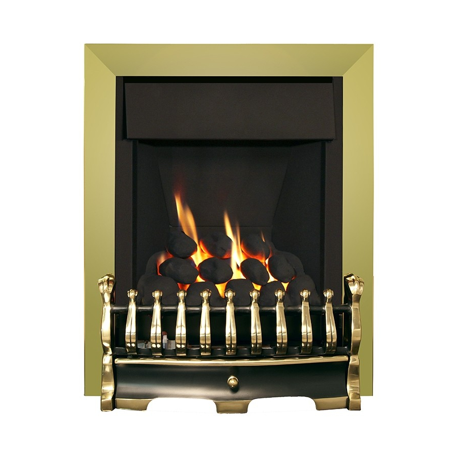
SECTION FIVE - USER INSTRUCTIONS 5.1 INSTALLATION INFORMATION CONDITIONS OF INSTALLATION It is the law that all gas appliances are installed only by a competent (e.g. GAS SAFE registered) Installer, in accordance with the installation instructions and the Gas Safety (Installation and Use) Regulations 1998. Failure to install appliances correctly could lead to prosecution. - Page 34 ABOUT YOUR NEW FLAVEL WINDSOR / STIRLING PLUS GAS FIRE The The Flavel Windsor & Stirling Plus coal effect gas fires incorporate a unique and highly developed fuel bed which gives the realism of a loose coal layout com- bined with realistic flames and glow. The use of durable ceramic material in the construction of the fuelbed components ensures long and trouble free operation.
-
Page 35: Operating The Fire (Manual Control Models)
OPERATING THE FIRE - MANUAL CONTROL MODELS 5.2.1 The controls are located behind the ashpan cover which is situated below the fret or contemporary ashpan cover. The controls, comprise a control valve to adjust the gas flow and a push button piezo igniter. -
Page 36: Operating The Fire (Electronic Flame Control Models)
OPERATING THE FIRE - ELECTRONIC FLAME CONTROL MODELS. 5.3.1 To light the fire using the EFC switch press and hold the power button continuously until the red light illuminates next to the operation symbol (this typically takes two seconds). As the red light illuminates release immediately the power button. - Page 37 LIGHTING THE APPLIANCE - ELECTRONIC FLAME CONTROL MODELS (CONTINUED) 5.3.3 To increase the heat input level of the fire’s burner pressing and releasing the + button will increase the heat input level one step at a time. Pressing the + button continuously will move the heat input level to the maximum.
-
Page 38: Manual Operation Of Elecronic Fire Control Models
MANUAL OPERATION OF ELECTRONIC FLAME CONTROL MODELS 5.4.1 These products can be operated manually should the need arise. The control valve is located at the base of the fire as shown below in figure Fig. 2 5.4.2 Ensure that the power isolation switch is in position “1” and the power indicator light is illuminated (red) as shown in figure 3 below. -
Page 39: Replacing The Batteries Electronic Flame Control Models
5.4.3 To operate the fire press and hold the “power” button as shown in figure 2 on the previous page for two seconds, release as soon as the red indicator light in figure 3 on the previous page illuminates. The burner will start its ignition sequence and light to the maximum heat input level. -
Page 40: 5.6 Spillage Monitoring System
5.6 SPILLAGE MONITORING SYSTEM All models regardless of control type are fitted with a spillage monitoring system which shuts down the fire if the evacuation of combustion products from the fire is affected by a partially or fully blocked flue. If this system operates the fire will go out. -
Page 41: Re-Assembling The Ceramics And Fuel Bed (Coal Models)
5.8 RE-ASSEMBLING THE FUEL-BED - COAL MODELS 5.8.1 Place the fuelbed base centrally on to the fuelbed support and push fully backwards to the rear face of the fibre boards Make sure that the fuelbed base is located centrally in the fire box, behind the retaining tabs as shown below in figure 4. - Page 42 5.8.3 Select 3 off coals and arrange along the rear of the fuelbed, using the ribs in the rear of the fuelbed as a guide for placement, see figure 6 below. Fig. 6 The exact position and fit of the coals may be finely adjusted to give the best appearance.
-
Page 43: Re-Asembling The Ceramics And Fuel Bed (Pebble Models)
RE-ASSEMBLING THE FUEL-BED - PEBBLE MODELS 5.9.1 Place the fuelbed base centrally on to the fuelbed support and push fully backwards to the rear face of the fibre boards Make sure that the fuelbed base is located centrally in the fire box, behind the retaining tabs as shown below in figure 7. - Page 44 5.9.3 Fit the three small pebbles onto the ribs in the fuelbed as shown below, ensuring that the rear flame paths as indicated are not interupted. See figure 9 below. Fig. 9 Beige pebbles to be positioned as indicated The exact position and fit of the pebbles may be finely adjusted to give the best appearance.
-
Page 45: User Replaceable Parts
USER REPLACEABLE PARTS The only user replaceable parts on this fire are the fuelbed components and coals / pebbles which may be replaced as described in the above section. Replacement of any other parts must be carried out by a competent person such as a GAS SAFE registered gas installer. - Page 46 Due to our policy of continual improvement and development the exact accuracy of illustrations and descriptions contained in this book cannot be guaranteed. Part No. B-170980 Issue 3 BFM Europe Ltd. Trentham Lakes Stoke-on-Trent Staffordshire ST4 4TJ www.bfm-europe.com Telephone - General Enquiries : (01782) 339000 Telephone - Service : (0844) 7700169 or (01782) 339008...
Need help?
Do you have a question about the Windsor and is the answer not in the manual?
Questions and answers