Table of Contents
Advertisement
,
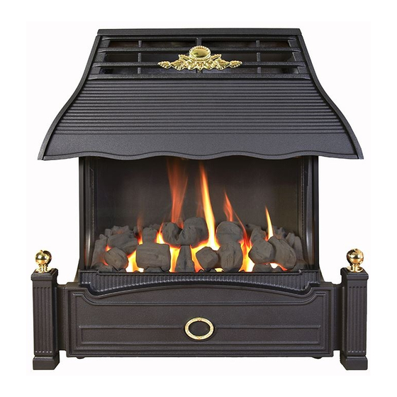
EMBERGLOW
CLASSIC
BATTERY IGNITION RADIANT CONVECTOR GAS FIRE
Installation, Maintenance & User Instructions
Hand these instructions to the user
Model No. FEMC00EN is for use on Natural Gas (G20) at a supply
pressure of 20 mbar in G.B. / I.E.
Model No. FEMC00EP is for use on Propane Gas (G31) at a supply
pressure of 37 mbar in G.B. / I.E.
Advertisement
Table of Contents

Related Manuals for Flavel EmberGlow Classic FEMC00EN


Summary of Contents for Flavel EmberGlow Classic FEMC00EN
- Page 1 EMBERGLOW CLASSIC BATTERY IGNITION RADIANT CONVECTOR GAS FIRE Installation, Maintenance & User Instructions Hand these instructions to the user Model No. FEMC00EN is for use on Natural Gas (G20) at a supply pressure of 20 mbar in G.B. / I.E. Model No.
-
Page 2: Table Of Contents
CONTENTS Contents Installation Instructions Page Appliance Data Section 1 Conditions of Installation. Flue & Chimney Suitability Fireplace/Surround Suitability Shelf Position Side Clearance Closure Plate Flue & Chimney inspection Chimney Catchment space 1.8.1 Brick Built Chimney 1.8.2 Fitting to Pre-Fab. Twin Wall Metal Flueboxes 1.8.3 Fitting to Pre-Cast Flue Installations... -
Page 3: Appliance Data
APPLIANCE DATA G20 Models G31 Models Main injector (1 off) Stereomatic size 360 Stereomatic size 160, Cat 82 Cat 82 Pilot Type. Copreci Single Flame Copreci Single Flame Type 21100 / 161 21100 / 179 Max. Gross Heat Input : 6.0 kW 5.70kW Min. -
Page 4: Conditions Of Installation
CONDITIONS OF INSTALLATION In Great Britain :- It is law that all gas appliances are installed only by a GAS SAFE registered installer in GB, in accordance with these installation instructions and the Gas Safety (Installation and use) Regulations 1998. Failure to install appliances correctly could lead to prosecution. -
Page 5: Fireplace/Surround Suitability
FIREPLACE / SURROUND SUITABILITY The fire is suitable for hearth mounting or wall mounting. It must not be fitted directly onto a carpet or other combustible material. It must not be fitted to combustible walls. This fire is suitable for the following hearth / surround types: Non-combustible hearths / surrounds. -
Page 6: Chimney Catchment Space
Brick / stone built chimneys and any chimney or flue which has been used for an appliance burning fuel other than gas must be thoroughly swept. The base of the chimney / flue must also be thoroughly cleared of debris etc. Any under floor air supply to the fireplace must be completely sealed off. - Page 7 The front opening of the fireplace must be between 305mm and 440mm wide, and between 500mm and 650mm high. If the opening is larger than this, then a surround must be constructed in a suitable non-com bustible material to create an opening to these limits. Allow a minimum flat surface of 20mm around the opening to ensure that the closure plate can be sealed to the fireplace.
-
Page 8: Fitting To Pre-Cast Flue Installations
1.8.3 Fitting to Pre-Cast Flue Installations. The pre-cast opening must be a minimum of 122.7cm 2 or equivalent cross-sectional area and have a minimum effective flue height of 3 metres. The flue spigot restrictor must be removed when installing into pre-cast flue applications. This appliance has been tested for use in a pre-cast flue block complying with BS EN 1858. -
Page 9: Packing Check List
PACKING CHECK LIST 1 off Cast Canopy 1 off Firebox / Burner Assembly 1 off Flue Spigot 1 off Closure Plate 1 off Literature / Loose Items Pack 1 off Fuelbed 1 off Coal Pack 1 off Cast Fender 1 off AA battery INSTALLATION OF FIRE 2.2.1 Preparation. - Page 10 Closure plate Fit the closure plate to the fireplace opening and ensure that it has a flat sealing area of at least 10mm sealed on all sides. See Fig. 3 below Dimensions stated are for closure plate supplied Check the operation of the chimney as follows:- Fig.
- Page 11 FITTING THE CANOPY REAR TRIM Secure the canopy rear trim to the canopy via the four fixings screws (2 off L/H & 2 off R/H) as shown below in Fig. 4 Fig. 4 2 off R/H Fixing Screws FITTING THE CANOPY TO THE FIREBOX Secure the canopy to the firebox with the four screws (2 off L/H &...
-
Page 12: Gas Tightness
FITTING THE SPIGOT TO THE FIREBOX Screw the firebox spigot to the draught diverter with the four screws, 2 off upper (as shown below in Fig. 6) & 2 off lower screws (not pictured) . Fig. 6 4 off Flue Spigot Fixing screws Note : A means of isolation must be provided near to the appliance to facilitate... -
Page 13: Fitting The Battery
FITTING THE BATTERY The battery holder is located at the bottom R/H/S of the fire, unscrew the cap, fit the AA battery supplied in the loose items pack and re-fit the cap. See Fig. 7 below. Fig. 7 Spark Generator Battery Cap AA Battery... -
Page 14: Assembly Of Fuelbed
ASSEMBLY OF THE FUELBED NOTE : The position of the fuel-bed components are critical to the performance of the product. Therefore please ensure that the fuel-bed components are positioned as described in the following section prior to requesting a service call due to soot build up, poor flame pattern etc. Fit the fuelbed base into the combustion chamber as shown below in Fig. - Page 15 Fit coal “B” onto the fuelbed base in the position as shown below in Fig. 10. The coal form has the individual placement letters stamped on the bottom face. Fig. 10 Coal Form “B” Fit coal “C” onto the fuelbed base in the position as shown below in Fig.
- Page 16 Fig. 12 Coal Form “D” Fit coal “E” onto the fuelbed base in the position as shown below in Fig. 13. The coal from has the individual placement letters stamped on the bottom face. Fig. 13 Coal Form “E” To ensure that the release of fibres from these R.C.F (Refractory Ceramic Fibre) articles is kept to a minimum, during installation and servicing we recommend that you use a HEPA filtered vacuum to remove any dust accumulated in and around the appliance before and after working on the...
-
Page 17: Lighting The Appliance
Refit the Front Casting, which locates onto the the two fixing screws. Note: It is important that the decorative Front Casting is fitted before attempting to use the fire. Lighting the Appliance Light the pilot by depressing the control knob at the “off” position and turn anti-clockwise (with the control depressed) to the second position marked *. -
Page 18: Final Checks
Fig. 14 Smoke Match position - Approximately 25mm below and from left hand edge of draught diverter (viewed from rear for clarity of image) Smoke match holder to be inserted at approximely 45 degree angle below side 45 degrees trim If there is an extractor fan fitted in a joining room, then the spillage test must be repeated with the fan switched on and running at maximum speed. -
Page 19: General Access For Servicing
MAINTENANCE INSTRUCTIONS Servicing Notes Servicing should be carried out annually by a competent person such as a Gas Safe registered engineer. The service should include visually checking the chimney and fire opening for accumulations of debris and a smoke test to check for positive up-draught in the chimney. - Page 20 Fig. 16 2 off R/H Burner Retaining Screws 2 off L/H Burner Retaining Screws Remove the four burner retaining screws as indicated in Fig. 16 above Slide the burner assembly to the right, off the injector and remove the from the firebox. REMOVING THE CONTROL TAP FROM THE FIRE Disconnect the appliance from the gas supply.
- Page 21 Remove the valve retaining nut as shown below and disconnect the wires to the microswitch as shown below in Fig. 18 Fig. 18 Valve retaining nut and microswitch wires Remove the thermocouple, which is a push fit into the rear of the control valve.
-
Page 22: Conditions Of Installation
5.1 INSTALLATION INFORMATION CONDITIONS OF INSTALLATION It is the law that all gas appliances are installed only by a competent (e.g. GAS SAFE Registered) Installer, in G.B. in accordance with the installation instructions and the Gas Safety (Installation and Use) Regulations 1998. Failure to install appliances correctly could lead to prosecution. - Page 23 ABOUT YOUR NEW FLAVEL EMBERGLOW GAS FIRE The Flavel Emberglow gas fire incorporates a unique and highly developed heat exchanger which combined with the coal effect gives maximum heat whilst maintaining reasonable running costs Please take the time to fully read these instructions as you will then be able to obtain the most effective and safe operation of your fire.
- Page 24 OPERATING THE FIRE Light the pilot by depressing the control knob at the “off” position and turn anti-clockwise (with the control depressed) to the second position marked *. When the pilot lights, (pilot can be seen between the coals and fuelbed base through the side window) hold the control knob down for 10 seconds.
- Page 25 LIGHTING WITH A SPILL Important do not light with a wax taper In the unlikely event of the piezo ignition unit failing to light the fire, turn the control knob to the OFF position, and wait a minute or so for the gas to disperse. The fire can then be lit by using a spill.
- Page 26 ASSEMBLY OF THE FUELBED NOTE : The position of the fuel-bed components are critical to the performance of the product. Therefore please ensure that the fuel-bed components are positioned as described in the following section prior to requesting a service call due to soot build up, poor flame pattern etc. Fit the fuelbed base into the combustion chamber as shown below in Fig.
- Page 27 Fit coal “B” onto the fuelbed base in the position as shown below in Fig. 3 The coal form has the individual placement letters stamped on the bottom face. Fig. 3 Coal Form “B” Fit coal “C” onto the fuelbed base in the position as shown below in Fig.
- Page 28 Fit coal “D” onto the fuelbed base in the position as shown below in Fig. 5. The coal form has the individual placement letters stamped on the bottom face. Fig. 5 Coal Form “D” Fit coal “E” onto the fuelbed base in the position as shown below in Fig.
-
Page 29: Replacing The Battery
To ensure that the release of fibres from these R.C.F (Refractory Ceramic Fibre) articles is kept to a minimum, during installation and servicing we recommend that you use a HEPA filtered vacuum to remove any dust accumulated in and around the appliance before and after working on appliance. - Page 30 Due to our policy of continual improvement and development the exact accuracy of descriptions and illustrations cannot be guaranteed. Part No. B-138550 Issue 2 BFM Europe Ltd Trentham Lakes Stoke-on-Trent Staffordshire ST4 4TJ Telephone - General Enquiries : (01782) 339000 Telephone - Service : (0844) 7700169...
Need help?
Do you have a question about the EmberGlow Classic FEMC00EN and is the answer not in the manual?
Questions and answers
Hello the plastic cap has lost its thread om my Flavel Emberglow Classic model number FEMCOOEN NEED TO BUY A NEW PLASTIC CAP THANK YOU