Table of Contents
Advertisement
POLARIS POWER™
Operator's Manual
(Australian model)
For your nearest Polaris supplier,
call 0393945610
or visit www.polarispower.com.au
Polaris Sales Australia Pty Ltd.,
(ABN 62088081949) of Locked Bag 2006,
Sunshine Post Shop,
Sunshine, Victoria, 3020
Australia
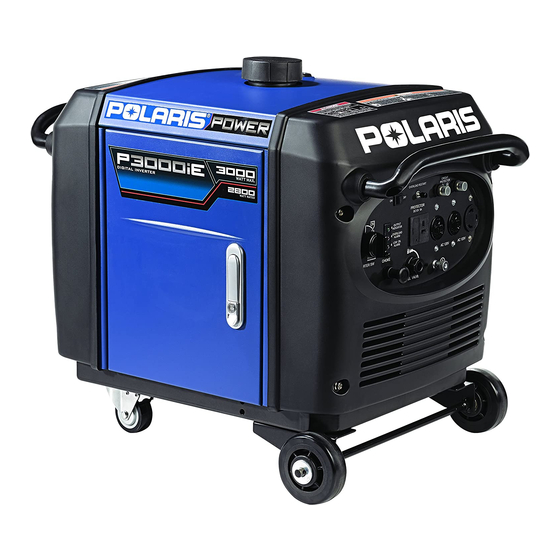
P3000iE
Failure to properly follow the instructions and precautions in
this manual can result in property damage, serious injury or
DEATH!
PMS 419
Part No. 9925472 Rev 02
Advertisement
Table of Contents

Related Manuals for Polaris P3000iE


Summary of Contents for Polaris P3000iE
- Page 1 (Australian model) Failure to properly follow the instructions and precautions in this manual can result in property damage, serious injury or DEATH! For your nearest Polaris supplier, call 0393945610 or visit www.polarispower.com.au Polaris Sales Australia Pty Ltd., (ABN 62088081949) of Locked Bag 2006,...
-
Page 2: Table Of Contents
TABLE OF CONTENTS Introduction ......2 Safety ....... . . 6 Controls and features . -
Page 3: Introduction
INTRODUCTION Welcome Thank you for purchasing a POLARIS POWER Generator, and welcome to our world-wide family of POLARIS owners. Here at POLARIS we proudly produce an exciting line of utility and recreational products. • Snowmobiles • All-terrain vehicles (ATVs) ®... -
Page 4: Intended Use
INTRODUCTION Intended Use The POLARIS Power Generator is intended to supply power for appliances. Appliances that use more than 2800 Watts of combined power consumption should not be connected to this generator. Safety Precautions Failure to follow recommended precautions and procedures could result in severe injury or death. -
Page 5: Signal Words And Safety Terms
INTRODUCTION Warnings, Cautions and Notices Signal Words and Safety Terms The following signal words and symbols appear throughout this manual. Your safety, and the safety of others, is involved when these words and symbols are used. Become familiar with their meaning before reading the manual. - Page 6 INTRODUCTION Identification Numbers and Locations Record your generator’s identification numbers in the space provided. The model and serial number decal is located inside the service door. Serial Number MODEL NUMBER: _______________________________________________________ SERIAL NUMBER: _______________________________________________________ PURCHASE DATE: _______________________________________________________ PURCAHSE LOCATION: __________________________________________________...
-
Page 7: Safety
SAFETY Safety Warnings and Precautions IMPORTANT SAFEY INSTRUCTIONS. SAVE THESE INSTRUCTIONS. Failure to follow recommended precautions and procedures could result in severe injury or death. Always read all safety precautions and follow all operation, inspection, and maintenance procedures outlined in this manual. - Page 8 SAFETY Safety Warnings and Precautions It is the responsibility of the owner to ensure that all users of this genera- tor are fully informed of the safety and operating information prior to use. Before and During Operation • Perform all Pre-Operation Inspection activities as shown on page 26 of this manual.
- Page 9 SAFETY Safety Warnings and Precautions Before and During Operation • Do not connect the generator to another power supply source. • The engine becomes extremely hot during and immediately after it has been in use. Be careful not to touch any parts of the hot engine, especially the muffler or muffler cover, or serious burns may result.
-
Page 10: Operator Safety
• Turn off the generator immediately if the unit begins to operate abnormally. After the generator has cooled, disconnect the generator and call your authorized POLARIS supplier. • While operating the generator, if you experience headache, fatigue, nausea / vomiting, confusion, or seizures, immediately get to fresh air. -
Page 11: Fuel Safety
SAFETY Safety Warnings and Precautions Fuel Safety Petrol is highly flammable and explosive under certain conditions. Always use caution when handling petrol. • Petrol is extremely flammable, and petrol vapor can explode. Before refueling allow the engine to cool completely if the generator has been in operation. - Page 12 SAFETY Safety Warnings and Precautions Carbon Monoxide Safety Generator exhaust contains Carbon Monoxide (CO) vapors. Exposure to Carbon Monoxide by people or pets can result in SEVERE INURY or DEATH. ALWAYS operate generator according to guidelines in labels and this manual. •...
-
Page 13: Electrical Safety
Overloading will damage the unit and / or shorten its operating lifespan. • Do not attempt to connect P3000iE generators in parallel. Fire Safety Generator exhaust system gets hot enough to ignite some materials and burn skin if touched. -
Page 14: Extension Cord Information
Equipment Modifications Modifying the generator by adding or removing any parts, components, or any modifications not approved by POLARIS may void the warranty. Such modifications may make the generator unsafe to operate and could result in severe injury to operators and / or bystanders, as well as damage to the generator. -
Page 15: Safety Labels And Locations
SAFETY Safety Labels and Locations Safety and warning decals have been placed on the generator for your protection. Read and follow the instructions of the decals and warnings on the generator carefully. If any of the decals depicted in this manual differ from the decals on your generator, always read and follow the instructions of the decals on the generator. - Page 16 SAFETY Safety Labels and Locations Improper Generator use can result in SEVERE INJURY or DEATH. Read the OWNER’S MANUAL. Follow all Instructions and Warnings. Petrol is flammable and explosive. Severe burns can result. ALWAYS stop the engine and let cool down before refueling. ALWAYS check for fuel leaks and wipe up any spills.
-
Page 17: Controls And Features
CONTROLS AND FEATURES Generator Components: ITEM NOMENCLATURE DESCRIPTION Provides proper starting mixture when Choke Knob engine is cold. Indicator Panel Low Oil, Overload, and Output LEDs Fuel Valve Lever Turns fuel supply to carburetor on and off. Automatically reduces engine speed when SMART Throttle Switch loads are shut off or disconnected. -
Page 18: Generator Components
CONTROLS AND FEATURES Generator Components: ITEM NOMENCLATURE DESCRIPTION Provides ground for non-conductive metal Ground Terminal parts and receptacle ground terminals. Provide two connections for properly rated, 240V AC Receptacle AC appliances. Fuel Level Indicator Provides indication of fuel level. Causes the recoil starter to crank the engine Starter Grip when pulled. -
Page 19: Choke Knob
CONTROLS AND FEATURES Choke Knob By moving to the CLOSE position, the choke knob (A) provides proper starting mixture when the engine is cold. Operates by being placed in the OPEN or CLOSE position. CLOSED OPEN Indicator Panel Low Oil Indicator The low oil alarm system is designed to prevent engine damage caused by an insufficient amount of oil in the crankcase. -
Page 20: Fuel Valve Lever
CONTROLS AND FEATURES Fuel Valve Lever When the engine is well-cooled and not in use, the fuel valve (C) must be placed in the OFF position to reduce the possibility of fuel leakage. It must be in the ON position to allow the engine to operate. - Page 21 CONTROLS AND FEATURES DC Receptacle and Fuse The DC receptacle is protected from an overload with a fuse. If the DC circuit is overloaded, the 5 amp fuse (F1) will blow and power to the DC receptacle will cease. The red light on the DC panel will illuminate.
-
Page 22: Ground Terminal
CONTROLS AND FEATURES Ground Terminal Ground terminal (H) connects to the frame of the generator metal parts that do not conduct current, and grounds terminals of each receptacle. Consult a qualified electrician, electrical inspector, or local agency having jurisdiction for local codes or ordinances for the Ground intended use of the generator before using the Terminal... -
Page 23: First Use Instructions
FIRST USE INSTRUCTIONS Adding Engine Oil Failure to use the recommended 4-stroke engine oil may result in engine damage, see page 64 for recommended oil and capacity. 1. Place the generator on a flat, level surface. Open the service door. See page 46. -
Page 24: Fuel Recommendation
FIRST USE INSTRUCTIONS Fuel Recommendation POLARIS recommends the use of 91 octane fuel or higher. Do not use fuel containing more than 10% ethanol. Do not use fuel with lower than 91 octane rating. IMPORTANT: Operating the generator with an obstructed fuel system will result in serious engine damage. - Page 25 FIRST USE INSTRUCTIONS Adding Fuel 1. Remove the fuel tank cap (A). 2. Fill carefully to avoid spilling fuel on the fuel tank strainer (B). Do not overfill the fuel tank (there should be no fuel above the upper limit mark). 3.
-
Page 26: Wheel Kit Installation
FIRST USE INSTRUCTIONS Wheel Kit Installation The unit comes with the rubber mounting feet installed. If you wish to install the wheel kit, please perform the following procedure. 1. Axle assembly (1) 2. Locking swivel wheel (2) 3. Bolt M8X16 (4) 4. -
Page 27: Pre-Operation Inspection
When inspection reveals the need for adjustment, replacement, or repair, perform service promptly or visit your authorized POLARIS supplier for assistance. Pre-Operation Checklist Open the service door to expose the generator inner components. See page 46. -
Page 28: Operation
OPERATION Safe Operating Precautions Fuel Recommendations The P3000iE engine is certified to operate on regular unleaded petrol with a pump octane rating of 91 or higher. Never use stale or contaminated petrol or an oil /petrol mixture. Avoid getting dirt or water in the fuel tank. -
Page 29: Safe Operating Precautions
OPERATION Safe Operating Precautions Refueling 1. Remove the fuel tank cap (A). 2. Fill carefully to avoid spilling fuel or exceeding the bottom of the fuel tank strainer (B). 3. Securely tighten the fuel tank cap (A) until it clicks. 4. -
Page 30: Before Starting The Engine
OPERATION Safe Operating Precautions Before Starting the Engine 1. Ensure the generator is away from the fueling source. DANGER 2. The generator will vibrate Using a generator indoors CAN KILL YOU IN MINUTES. Generator exhaust contains carbon monoxide. during operation. Place the This is a poison you cannot see or smell. - Page 31 OPERATION Safe Operating Precautions Starting the Engine 6. To start the generator using the ignition key, turn the ignition switch to the START position. When the engine starts, release the key. Do not operate the starter for more then 10 second intervals.
-
Page 32: Stopping The Engine
OPERATION Safe Operating Precautions Starting the Engine 10. If connecting loads to generator, reference “AC Operation” or “DC Operation” as outlined later in this Operation section. 11. Make sure to turn the AC switch to "ON" AC Switch position. Otherwise, there will be no AC power output from AC receptacles. - Page 33 Note: When the electric motor starts, the overload indicator (middle light) may illuminate (RED) and extinguish within 4 seconds. If the overload indicator remains illuminated, consult your POLARIS supplier. 1. Perform “Starting the Engine” (29) and ensure that the output indicator (A) illuminates (GREEN).
- Page 34 OPERATION Safe Operating Precautions AC Operation Note: Should this current be exceeded, the circuit protection device will activate and cut all current to the receptacle. This will be indicated by the push button popping out. Unplug everything that is plugged into the receptacle and reset the circuit protector by pushing in the button and then push in the Overload Reset switch.
- Page 35 OPERATION Safe Operating Precautions AC Capacity Note: Typical wattages are listed in the table below. Before plugging any device into the generator, verify the manufacturer-listed wattage on the device. Wattage Reference Table ADDITIONAL RUNNING DEVICE STARTING (SURGE) (RATED) WATTS WATTS Circular Saw - 7 1/4”...
-
Page 36: Power Management
OPERATION Safe Operating Precautions Power Management ADDITIONAL RUNNING DEVICE STARTING (SURGE) (RATED) WATTS WATTS Microwave oven 1000 1400 Coffee maker 1000 Total Running (Rated) Watts = 2000 Additional Starting Surge Watts = 1400 Total Generator Output Required = 3400 Ensure the combined electrical rating of the powered device(s) do not exceed the maximum allowed by the generator. -
Page 37: Connecting The Battery Charging Cable
OPERATION Safe Operating Precautions DC Operation Connecting the Battery Charging Cable The DC charging output is not regulated. The DC receptacle should only be used for charging 12V DC batteries. The 12V DC receptacle has no battery overcharge protection function. Do not overcharge the battery. The DC output is to be used to charge batteries only. -
Page 38: Disconnecting The Battery Charging Cable
If the DC overload fuse Door continues to blow, discontinue charging and see your authorized POLARIS generator supplier. The overload fuse does not prevent overcharging the battery. The fuse is located to the left of the receptacle and is accessed by snapping open the access door. -
Page 39: Air Conditioning Operation
OPERATION Safe Operating Precautions Air Conditioning Operation For best results, the SMART throttle switch should be in the off position. Bring the generator to a normal operating temperature before applying the air conditioning load. Always allow a 2 minute wait period when manually cycling an air conditioner off and on. -
Page 40: Standby Power
OPERATION Safe Operating Precautions Standby Power Improper connection to a building electrical system can allow current from the generator to back feed into the utility lines. Such back feed may electrocute utility company workers or others who contact the lines during a power outage. -
Page 41: Carburetor Modification
High altitude operation can be improved by specific modifications to the carburetor. If always operating the generator at altitudes above 1500 meters (5000 feet), have an authorized POLARIS servicing supplier perform the carburetor modification. The engine will meet each emission standard throughout its life when operated at high altitude with the carburetor modifications for high altitude operation. -
Page 42: Emission Control System Information
NOx, hydrocarbons. POLARIS utilizes appropriate air-fuel ratios and other emissions control systems to reduce the emissions of carbon monoxide, oxides of nitrogen, and hydrocarbons. In addition, POLARIS fuel systems utilize components and control technologies to reduce evaporative emissions. -
Page 43: Replacement Parts
The emission control system on the engine was designed, built, and certified to conform to applicable emission regulations. We recommend the use of POLARIS Genuine parts whenever maintenance is performed. These original design replacement parts are manufactured to the same standards as the original parts. The use of replacement parts that are not of the original design and quality may impair the effectiveness of the emission control system. -
Page 44: Maintenance
To ensure the best quality and reliability, use only new, POLARIS Genuine parts or their equivalents for repair and replacement. All necessary replacement parts and labor incurred, with the exception of authorized warranty repairs, become the responsibility of the registered owner. -
Page 45: Maintenance Safety
If you do not have the time, tools, and/or expertise necessary to complete a procedure properly, please see your POLARIS supplier for service. Failure to correct a problem before operation and improper maintenance can cause a malfunction resulting in injury or death. Always follow the inspection and maintenance schedules and requirements in this manual. -
Page 46: Periodic Maintenance
(1) Log hours of operation to determine proper maintenance. (2) Service more frequently when used in dusty conditions. (3) These items should be serviced by an authorized POLARIS supplier unless the owner has the proper tools and is mechanically proficient. Refer to the POLARIS Service manuals. -
Page 47: Opening The Service Door
MAINTENANCE Opening the Service Door Use the following steps to open the generator service door and gain access to the inner components. Before performing any maintenance, the ignition switch should be positioned to OFF. See page 19. Note: Use this procedure to open the service door on either side of the generator. -
Page 48: Fuel System
MAINTENANCE Opening the Service Door 4. Expose the generator inner components by swinging open the service door (D). Perform maintenance as needed. 5. Upon completion of maintenance, close the service door (D), engage the latch (C) by turning counter clock wise and pushing in securing with the lock slider (B), and position the ignition switch (A) to the ON position to allow generator... - Page 49 MAINTENANCE Fuel System Fuel Tank Strainer 1. Remove the fuel tank cap (A). 2. Remove the fuel tank strainer (B) from the fuel tank. 3. Remove any foreign objects or debris from the fuel tank strainer (B). 4. Inspect the fuel tank strainer (B) for damage. Replace as needed. 5.
-
Page 50: Engine Oil
The SAE oil viscosity and service category are in the API label on the oil container. POLARIS recommends the use of API service category “SJ” or later, equivalent oil. Oil Level Inspection Failure to use the proper 4-stroke engine oil may result in engine damage. -
Page 51: Oil Change
MAINTENANCE Engine Oil Oil Change Oil may be hot. Do not allow hot oil to come into contact with skin, as serious burns may result. Note: Drain the oil while the engine is warm to assure rapid and complete draining. 1. - Page 52 MAINTENANCE Engine Oil Oil Change Note: Improper disposal of engine oil can be harmful to the environment and is unlawful. Properly dispose of used oil. 6. Drain the used oil into a sealed container and take it to a recycling center.
- Page 53 MAINTENANCE Air Filters Air Filter Inspection Do not use petrol or low flash point solvents for cleaning. They are flammable and explosive under certain conditions. Note: An obstructed air filter restricts air flow to the carburetor. To prevent carburetor malfunction, regularly service the air filter. Service more frequently when operating the generator in extremely dusty areas.
-
Page 54: Spark Plug
MAINTENANCE Spark Plug Spark Plug Inspection and Replacement Using a non-recommended spark plug can result in serious engine damage. Always use recommended spark plugs. Note: In order to service the spark plug, the provided spark plug wrench is required. Refer to the Specification section (see page 64) for the recommended spark plug type. - Page 55 MAINTENANCE Spark Plug Spark Plug Inspection and Replacement 3. Clean any dirt from around the base of the spark plug. 4. Using the provided park plug wrench (B), remove the spark plug. 5. Inspect the electrode for wear Inspect electrode and carbon buildup.
-
Page 56: Battery Safety
MAINTENANCE Battery Battery Safety Always disconnect the negative (black) cable first when removing the battery. Always connect the negative (black) cable last during installation. Failure to properly connect/disconnect battery cables may result in an explosion and cause serious injury or death. Battery electrolyte contains sulfuric acid which is poisonous and can cause serious burns. -
Page 57: Maintenance Battery
MAINTENANCE Battery Battery Charging (Sealed Only) Note: This procedure applies only to the sealed battery (recommended). 1. Using a voltmeter or multi-meter, check the battery to ensure a minimum 12.8V DC or higher. 2. If the voltage is less than 12.8V DC, recharge the battery at 1.2 amps or less until the battery voltage is 12.8V DC or greater. -
Page 58: Spark Arrestor
MAINTENANCE Spark Arrestor Spark Arrestor Maintenance Generator exhaust system gets hot enough to ignite some materials and burn skin if touched. Allow generator and exhaust to cool before performing spark arrestor maintenance. The spark arrester must be serviced every 100 hours to maintain its efficiency. -
Page 59: Transportation And Storage
TRANSPORTATION AND STORAGE Transportation Transporting the Generator A hot engine or exhaust system can cause severe burns and ignite flammable material. Ensure adequate time for cooling before storage or transportation. When operating or transporting the generator, be sure it is kept upright. If the generator tilts, fuel may leak. -
Page 60: Storage Preparation
TRANSPORTATION AND STORAGE Storage Storage Preparation Petrol is highly flammable and explosive and can cause serious injury. Stop the engine and keep heat, sparks, and flame away. Handle fuel only outdoors. Wipe up spills immediately. Note: Long-term storage of the generator will require some additional preventative measures to guard against deterioration. -
Page 61: Accessing The Fuel Tank
TRANSPORTATION AND STORAGE Storage Accessing the Fuel Tank 1. Remove the fuel tank cap (A). 2. Remove the fuel tank strainer (B) from the fuel tank. Remove debris as needed. 3. When maintenance is complete, re- install the fuel tank strainer (B) into the fuel tank. - Page 62 1. Access the fuel tank. See page 60. 2. Empty the fuel tank into an approved petrol container. POLARIS recommends using a commercially available petrol hand pump to empty the tank. Do not use an electric pump.
- Page 63 TRANSPORTATION AND STORAGE Storage Fogging the Engine 1. Turn the ignition key to the OFF position. 2. Open the service door. See page 46. 3. Remove the spark plug cap (A). 4. Using the provided park plug wrench (B), remove the spark plug.
-
Page 64: Storage Precautions
TRANSPORTATION AND STORAGE Storage Battery Storage Do not store the generator outdoors in the cold weather when not in use. Storage Precautions Do not store the generator outdoors in the cold weather when not in use. • Select a well-ventilated storage area away from any flame-operated appliance (i.e., furnace, water heater, or clothes dryer). -
Page 65: Specifications
3600 RPM with smart throttle off Cooling System Forced Air Ignition System Transistorized Engine Oil POLARIS 5W-30 Generator Oil Engine Oil Capacity 0.6 L (0.63 qt) Intake Valve Clearance-Cold 0.10 mm (.004 in.) Exhaust Valve Clearance-Cold 0.15 mm (.006 in.) Spark Plug WR7DC 0.6 - 0.7 mm (.024 - .028in.) -
Page 66: General Specifications
AC/DC Simultaneously Usage POLARIS Lubricants and Maintenance Products ENGINE OIL PART NUMBER DESCRIPTION 2879383 POLARIS 5W-30 Generator Oil (1 Quart) (32 oz.) GREASE / SPECIALIZED LUBRICANTS 2871329 Dielectric Grease (Nyogel™) ADDITIVES 2871326 Premium Carbon Clean / Fuel Stabilizer (12 oz.) (12 count) -
Page 67: Wiring Diagram
WIRING DIAGRAM Charging regulator Starting motor Starting relay Ignition winding Trigger winding Low oil pressure switch Spark plug Ignition coil Single-phase receptacle... -
Page 68: Troubleshooting
Troubleshooting Symptoms Engine Will Not Turn Over POSSIBLE CAUSE SOLUTION Starter recoil damage Take the generator to an authorized POLARIS servicing supplier or refer to the service manual Low battery voltage Recharge the battery to 12.8V DC Starter motor damaged... -
Page 69: Engine Lacks Power
Drain the fuel system and refuel without treating or draining petrol, or refueled with bad petrol Mechanical failure Take the generator to an authorized POLARIS servicing supplier or refer to the service manual Engine Backfires POSSIBLE CAUSE SOLUTION Weak spark from spark plug Inspect, clean, and / or replace spark plug... - Page 70 Poor quality or low octane Drain the fuel system and refuel fuel Incorrect ignition timing Take the generator to an authorized POLARIS servicing supplier or refer to the service manual Incorrect spark plug gap or Set gap to specification or replace spark plugs...
- Page 71 Kinked or plugged fuel tank Inspect and replace vent Low octane fuel Drain the fuel system and refuel Carburetor jetting incorrect Take the generator to an authorized POLARIS servicing supplier or refer to the service manual POSSIBLE RICH SOLUTION FUEL CAUSE Incorrect fuel...
- Page 72 No Power at AC Receptacles POSSIBLE CAUSE SOLUTION Output indicator is OFF, and Take the generator to a POLARIS servicing supplier or overload indicator is ON refer to the service manual AC circuit protector tripped Check AC load and reset circuit protector...
-
Page 73: Warranty
POLARIS POWER™ generator to you if that person has breached their sales contract with you. -
Page 74: Warranty Policy
Warranty repairs Repairs and replacements covered under this POLARIS POWER™ Generator Warranty will be carried out free of charge by Polaris. However you will be responsible for any costs associated with making the warranty claim including but not limited to: a. -
Page 75: Warranty Exclusions
Your will not be entitled to make a claim under this POLARIS POWER™ Generator Warranty: a. in respect of any fault or damage which, in Polaris' reasonable opinion, has been caused by or arises from: your failure to operate or maintain your POLARIS POWER™ generator in accordance with the manufacturer's specifications and the instructions in the relevant Operator's Manual;... - Page 76 Australian laws, including the Australian Consumer Law (see page 72). To the extent that the law permits and allows Polaris to exclude or limit its liability, Polaris under this POLARIS POWER™ generator Warranty accept no responsibility for the loss of use of the POLARIS POWER™...
- Page 77 WARRANTY IMPORTANT NOTICE To aid in prompt support of any in-service or POLARIS POWER ™ Generator Warranty queries that may arise, it is highly important that current ownership details are on file with Polaris. Therefore it is vital that should you change the details of your POLARIS POWER™...
-
Page 78: Maintenance Log
MAINTENANCE LOG Present this section of your manual to your supplier each time your generator is serviced. This will provide you and future owners with an accurate log of maintenance and services performed. SERVICE SUPPLIER / DATE/HOURS COMMENTS PERMORMED TECHNICIAN Initial/20 hr 3 months/50 hr 6 months/100 hr... -
Page 79: Index
INDEX AC Capacity....33-34 Fuel System ....47 AC Operation. - Page 80 INDEX Periodic Maintenance Chart ..45 Pre-Operation Checklist ..26 Problems Affecting Emissions ..42 Refueling....27-28 Registration, Warranty .
- Page 81 PMS 419...