Table of Contents
Advertisement
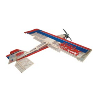
Specifications
Wingspan: .............................................................. 76 in (1676mm)
Length:.................................................................... 55 in (1397mm)
Wing Area: ............................................................ 2 AIL: 1210 sq in (5934.5 sq dm)
Weight (approximate):........................................ 9–11 lb (2.7–3.15 kg)
Recommended Engines: ..................................... 2-cycle: 1.08–.150 cu in
ASSEMBLY MANUAL
4 AIL: 1230 sq in (6025.5 sq dm)
4-cycle: 1.00–1.80 cu in
TM
®
WE GET PEOPLE FLYING
TM
Advertisement
Table of Contents

Related Manuals for Horizon Hobby Ultra Stick Lite


Summary of Contents for Horizon Hobby Ultra Stick Lite
-
Page 1: Specifications
® WE GET PEOPLE FLYING ASSEMBLY MANUAL Specifications Wingspan: .............. 76 in (1676mm) Length:..............55 in (1397mm) Wing Area: ............2 AIL: 1210 sq in (5934.5 sq dm) 4 AIL: 1230 sq in (6025.5 sq dm) Weight (approximate):........9–11 lb (2.7–3.15 kg) Recommended Engines: ........ -
Page 2: Table Of Contents
Section 17: Balancing the Ultra Stick Lite ........ -
Page 3: Additional Required Equipment
Contents of Kit Large Parts A. Fuselage HAN2327 B. Wing Set with Joiner HAN2326 C. Tail Set HAN2328 D. Landing Gear HAN2329 E. Quad-Flap Set HAN2330 Additional items sold separately Decal Set (not shown) HAN2331 Additional Required Equipment Radio Equipment Recommended Engines •... -
Page 4: Additional Required Tools And Adhesives
Additional Required Tools and Adhesives Tools Other Required Items • Canopy Scissors • Epoxy brushes • Drill • Felt-tipped pen or pencil • Drill Bit: 1/16", 3/32", 1/8", 7/32", 1/4" • File • Flat blade screwdriver • Foam: 1/2" • Hobby knife •... -
Page 5: Warranty Information
Warranty Information Horizon Hobby, Inc. guarantees this kit to be free from defects in both material and workmanship at the date of purchase. This warranty does not cover any parts damage by use or modification. In no case shall Horizon Hobby's liability exceed the original cost of the purchased kit. -
Page 6: Section 1: Conventional Wing Assembly
Section 1: Conventional Wing Assembly Required Parts Step 2 Remove each hinge from the wing panel and place a • Left wing panel with aileron and hinges T-pin in the center outside edge of each hinge. Slide • Right wing panel with aileron and hinges each hinge into the wing panel until the T-pin is snug Required Tools and Adhesives against the wing. - Page 7 Section 1: Conventional Wing Assembly Step 4 Step 6 Deflect the aileron and completely saturate the hinge with Using CA remover/debonder and a paper towel, thin CA glue. The aileron’s front surface should lightly remove any excess CA glue that may have accumulated contact the wing during this procedure.
-
Page 8: Section 1A: Quad-Flap Wing Assembly
Section 1a: Quad-Flap Wing Assembly Required Parts Step 3a Slide the aileron and flap control surface onto the wing • Left wing aileron/flap panel until there’s only a slight gap (approximately 1/32"). • Right wing aileron/flap The hinges are now centered on the wing panel and the •... - Page 9 Section 1a: Quad-Flap Wing Assembly Step 5a Step 8a Turn the wing panel over and deflect the aileron and flap After both the aileron and flap control surfaces are in the opposite direction from the previous step. Apply securely hinged, firmly grasp the wing, flap, and aileron thin CA glue to each aileron hinge, making sure the CA to check that they are securely glued and cannot be penetrates into the aileron, flap and the wing.
-
Page 10: Section 2: Joining The Wing Halves
Section 2: Joining the Wing Halves Required Parts Step 3 The Ultra Stick™ Lite is designed with "0" dihedral. Place • Right/left wing panels the wing on a large flat surface. The spar, (high point of • Plastic wing bags (optional) the wing), should be flat on the surface. - Page 11 Section 2: Joining the Wing Halves Step 6 Step 8 Place one wing half right side up on a flat work surface. Apply a generous amount of epoxy into the wing joiner Using an epoxy brush, smear a generous amount of cavity of the other wing panel.
- Page 12 Section 2: Joining the Wing Halves Step 10 Step 11 Carefully slide the two wing halves together and firmly Apply masking tape at the wing joint to hold the wing press them together, allowing the excess epoxy to run out. halves together securely.
-
Page 13: Section 3: Aileron/Flap Servo Installation
Section 3: Aileron/Flap Servo Installation Required Parts Step 2 Install the recommended servo hardware supplied with • Assembled wing your radio system onto your servos, (grommets and • 12" Servo extension (2) eyelets). Install 12" servo extensions on the flap servo (2 additional 24"... - Page 14 Section 3: Aileron/Flap Servo Installation Step 4 Step 8 With the servo in place, mark the location of the servo Locate the two circular servo lead exits near the center screws and then remove the servo. of the wing bottom. Using a sharp hobby knife, trim away the covering to expose the openings, making sure to use caution so you don’t cut into the wing sheeting.
- Page 15 Section 3: Aileron/Flap Servo Installation Step 10 Step 12 Once the string is threaded though the wing, you can Securely fasten the servo in the opening with four of fish it out with your fingers or let the weight drop out the servo mounting screws supplied with your radio the opening.
-
Page 16: Section 4: Bolting The Wing To The Fuselage
The Ultra Stick Lite comes with the wing bolt T-nuts preinstalled in the fuselage. - Page 17 Section 4: Bolting the Wing to the Fuselage Step 4 Step 6 After the epoxy has cured for the leading edge alignment Using a ruler and felt-tipped pen, measure and mark dowels, trial fit the wing to the fuselage by inserting the the center of the fuselage at the tail end just above the dowels into the former in front of the wing saddle of the horizontal stabilizer mounting saddle.
- Page 18 Section 4: Bolting the Wing to the Fuselage Step 8 Step 10 Check the alignment of the wing by measuring the Remove the wing from the fuselage and using a sharp distance from the wing tip to the T-pin you installed in hobby knife, carefully trim away the covering on the wing Step 6.
-
Page 19: Section 5: Horizontal Stabilizer Installation
Section 5: Horizontal Stabilizer Installation Required Parts Step 2 On the bottom of the aft end of the fuselage is a saddle • Horizontal stabilizer • Fuselage cut out for the horizontal stabilizer to be mounted. Make • Assembled wing a center mark on the back of the saddle and place the Required Tools and Adhesives horizontal stabilizer into the horizontal stabilizer saddle. - Page 20 Section 5: Horizontal Stabilizer Installation Step 4 Step 7 With the fuselage and horizontal stabilizer resting on a flat Remove the horizontal stabilizer from the fuselage and surface, align the horizontal stabilizer by measuring from using a sharp hobby knife and a straight edge, carefully fixed points on the wing to the outside of the trailing edge trim away the covering approximately 1/16"...
- Page 21 Section 5: Horizontal Stabilizer Installation Step 9 Step 10 Mix approximately 1/2 ounce (minimum) of Lay the horizontal stabilizer onto a flat surface and 30-minute epoxy to install the horizontal stabilizer position the fuselage onto it, making sure it is to the fuselage.
-
Page 22: Section 6: Vertical Stabilizer (Fin) Installation
Section 6: Vertical Stabilizer (Fin) Installation Required Parts Step 3 Insert the vertical stabilizer into the slot in the top of the • Vertical stabilizer • Fuselage fuselage and make sure it’s firmly seated against the top Required Tools and Adhesives of the fuselage. - Page 23 Section 6: Vertical Stabilizer (Fin) Installation Important: It is essential the vertical Step 5 stabilizer base be epoxied to the inside the Remove the vertical stabilizer. Using a sharp hobby knife fuselage to provide adequate strength. Be and straightedge, carefully cut away the covering on the sure to use plenty of epoxy! vertical fin and fuselage approximately 1/16"...
-
Page 24: Section 7: Rudder And Tail Wheel Assembly Installation
Section 7: Rudder and Tail Wheel Assembly Installation Required Parts Step 2 Remove the rudder from the vertical fin and use a • Fuselage • Rudder 3/32” drill bit to drill the hole for the tail wheel wire. • Hinges •... - Page 25 Section 7: Rudder and Tail Wheel Assembly Installation Step 4 Step 6 Trial fit the rudder and tail wheel assembly to the vertical Mix approximately 1/2 ounce of 30-minute epoxy and fin. Note that the rudder will require trimming to allow apply it to both the nylon bushing of the tail wheel clearance for the tail wheel wire/bushing.
- Page 26 Section 7: Rudder and Tail Wheel Assembly Installation Step 8 Step 9 Once the CA has cured, check for security of the Slide the tail wheel onto the tail wheel wire. Next secure rudder by gently trying to pull the rudder from the fin. the wheel with the included wheel collar and setscrew.
-
Page 27: Section 8: Hinging The Horizontal Stabilizer And Elevator
Section 8: Hinging the Horizontal Stabilizer and Elevator Required Parts Step 2 With the elevator aligned (left and right), apply thin CA • Fuselage • Elevator glue to the hinges on both sides. Wipe away any excess • Hinges CA with CA remover/debonder and a paper towel. Required Tools and Adhesives •... -
Page 28: Section 9: Rudder And Elevator Control Horn Installation
Section 9: Rudder and Elevator Control Horn Installation Required Parts Step 2 Place the center of the control horn on the elevator at • Control horns (2) • Fuselage the mark made in the previous step. Mark the positions • Control horn backplates (2) for the control horns with a felt-tipped pen or pencil. - Page 29 Section 9: Rudder and Elevator Control Horn Installation Step 4 Step 6 Using the screws and backplate provided, attach Center the control horn over the mark you’ve just made. the elevator control horn and fasten in place with a Make sure the horn is positioned over the hinge line, just Phillips screwdriver.
-
Page 30: Section 10: Main Landing Gear Installation
Section 10: Main Landing Gear Installation Required Parts Note: You can use a Moto-tool to cut the extra length off the axle. Be very careful not to • Main landing gear • Fuselage get the axle too hot during the cutting process •... -
Page 31: Section 11: Fuel Tank Assembly
Section 11: Fuel Tank Assembly Required Parts Step 2 Locate the rubber stopper. Insert the short brass fuel • Metal tubes (2) • Clunk (fuel pickup) tube into one of the holes in the stopper so that an • Fuel pickup tubing •... - Page 32 Section 11: Fuel Tank Assembly Step 4 Step 7 Locate the longer brass fuel tube and bend it as shown Carefully insert the assembly into the fuel tank. Note using your fingers. This will be the fuel tank vent tube. the position of the vent tube.
-
Page 33: Section 12: Mounting The Engine
Section 12: Mounting the Engine Required Parts Step 2 Place your engine onto the installed mounting rails and • Throttle pushrod tube • Fuselage measure the distance from the firewall to the engine drive • Engine • Assembled fuel tank washer (5 ⁄... - Page 34 Section 12: Mounting the Engine Step 4 Step 5 Before installing your engine and engine mount, insert the Using Locktite Z-42 on the engine mount screws, fuel tank into the fuselage. The two pieces of fuel tubing install the engine mount to the firewall. Mount the should exit through the center hole in the firewall.
-
Page 35: Section 13: Radio System Installation
Section 13: Radio System Installation Required Parts Step 2 Use radio packing foam (not included, available • Fuselage at your local hobby shop) when installing the receiver • Radio packing foam (not included) and battery. • Antenna tube (optional, not included) •... - Page 36 Section 13: Radio System Installation Step 4 Step 6 Wrap the receiver battery in foam and place it in the Using a 1/16" drill bit, drill two mounting holes for the fuselage area forward of the servo tray and receiver. We switch as marked.
-
Page 37: Section 14: Aileron And/Or Quad-Flap Linkage Installation
Section 14: Aileron and/or Quad-Flap Linkage Installation Required Parts Step 2 Before assembly and mounting the linkages/control • Wing assembly w/servos installed horns, it’s a good idea to center the wing servos. Connect • 7 ⁄ " rods, threaded on one end them to the receiver, turn on your transmitter, then the (2 for conventional wing, 4 for quad flaps) receiver. - Page 38 Section 14: Aileron and/or Quad-Flap Linkage Installation Step 3 Step 6 The control horn should be positioned so the holes Attach the control horn to the aileron (flap) using the the clevis connects into are over the hinge line of the screws and the control horn backplate.
- Page 39 Section 14: Aileron and/or Quad-Flap Linkage Installation Step 8 Step 10 With the linkage attached to the control horn, center the Attach a wire keeper to the end of the rod with the control surface and hold the linkage wire directly over the 90-degree bend.
-
Page 40: Section 15: Rudder, Elevator And Throttle Pushrod Installation
Section 15: Rudder, Elevator and Throttle Pushrod Installation Required Parts Step 2 Note that the pushrod wire guide tubes are preinstalled in • Control horn (2) • Fuselage the fuselage. On the aft end of the fuselage find the • Wire keeper (2) •... - Page 41 Section 15: Rudder, Elevator and Throttle Pushrod Installation Step 4 Step 6 With the clevis attached to the control horn, center the Attach a wire keeper to the end of the rod with the control surface and hold the pushrod wire directly over 90-degree bend you just made.
- Page 42 Section 15: Rudder, Elevator and Throttle Pushrod Installation Step 9 Step 11 Locate the smaller 1.5mm, 19 ⁄ " pushrod and thread Connect the clevis end of the pushrod to the throttle arm. a clevis onto the threaded end. Insert the rod into the throttle pushrod tube previously installed.
-
Page 43: Section 17: Balancing The Ultra Stick Lite
4" left Flaps ⁄ " down Section 17: Balancing the Ultra Stick Lite An important part of preparing the aircraft for flight is The recommended Center of Gravity (C.G.) location for properly balancing the model. This is especially important the Ultra Stick™ Lite is 4 ⁄... -
Page 44: Section 18: Quad Flaps
Check to see if the nose pitches up or down and adjust the elevator-mixing value after landing if necessary. Try some steep descents with Crow and notice that the Ultra Stick Lite builds up very little speed on the Crow way down. Shoot some landings with Crow activated. - Page 45 (i.e. a right aileron input causes the inside and outside loops. Using the recommended right aileron and right flap to go up and the left aileron throws, the Ultra Stick Lite is capable of very tight and left flap to go down). 15-foot diameter loops.
- Page 46 Be full right aileron and full right rudder). You’ll find snaps ready for the Ultra Stick Lite to break ground and head for and spins tighter, faster and more aggressive. the skies! It’s important to release up elevator when the airplane breaks ground, then turn off the flaps to resume flights.
-
Page 47: Section 19: Radio Programming Guide
Section 19: Radio Programming Guide Following is a programming guide that provides step-by- If you come up with any interesting ideas, we’d like to step illustrations on how to program quad-flap hear from you. configurations for JR’s XP652/642, XP783/347/388S, Note: If you have a computer radio that’s not listed, XP8103, and 10X/10SxII/10Sx radios, as well as for please consult the instructions included with that Futaba’s 8-channel 8UA/S radio. - Page 48 Programming Guide — JR™ XP652/642 R S T INDICATES DATA RESET FUNCTION MODEL TYPE TO RESET — ENTER CLEAR MODE CHANNEL INCREASE DECREASE Press the MODE button Press the INCREASE and until "RST" appears on DECREASE buttons simultaneously the screen. to reset the data (a beep will sound).
- Page 49 Programming Guide — JR™ XP652/642 INDICATES THE SUB-TRIM FUNCTION CHANNEL THR: THROTTLE AIL: AILERON T H R SB-TRIM ELE: ELEVATOR RUD: RUDDER GER: LANDING GEAR FLP: FLAP (AC ONLY) ± SUB-TRIM VALUE ( 125) — ENTER CLEAR MODE CHANNEL INCREASE DECREASE Press the Press the...
- Page 50 Programming Guide — JR™ XP652/642 INDICATES THE DUAL-RATE FUNCTION Note: The dual-rate switch position CHANNEL is changed/accessed by setting the AI : AILERON appropriate dual-rate switch to the 0 EL : ELEVATOR or 1 positions. A I O SWITCH POSITION (0 OR 1) DUAL-RATE VALUE (0—125%) ENTER CLEAR...
- Page 51 Programming Guide — JR™ XP652/642 CURRENT MIX – CLEAR ENTER A 3 5 INCREASE DECREASE MODE CHANNEL CURRENT MIX CHANNELS Press the MODE button until “MIXA11” appears on the screen. Step 8. Mixing elevator-to-flaps: Press the Mode key until the Press the Decrease key until -35% is achieved.
- Page 52 Programming Guide — JR™ XP652/642 Takeoff Flap Switch Crow Switch Elevator-To-Flap Mix can be assigned to one of these switches or always left on. Note: The takeoff flaps should be retracted before using the Crow function to prevent any over-travel of the flap servos.
-
Page 53: Programming Guide - Jr Xp783/Xp347/Xp388S
Programming Guide — JR™ XP783/XP347/XP388S Programming the JR XP783, XP347 and XP388S in 15 Easy Steps JR’s XP783, XP347 and XP388S all feature the same base level Note: Most of the quad-flap features needed for the Ultra Stick™ Lite programming, so the procedure for setting up quad flaps for each are already preprogrammed in the glider (referred to as GLID) software radio is identical. - Page 54 Programming Guide — JR™ XP783/XP347/XP388S GLID T Y P E Function Being Select Aircraft Type Programmed HELI: Helicopter ACRO: Airplane GLID: Glider – Select Aircraft Type Step 2. Selecting model type (GLID): In System Setup mode, Now press the (+) key until “GLID” appears on the screen. press the Up key until the “TYPE”...
- Page 55 Programming Guide — JR™ XP783/XP347/XP388S Function Being Programmed THRO: Throttle AILE: Aileron ELEV: Elevator NORM REVERSE SW RUDD: Rudder GEAR: Gear (Left Aileron - Aileron 1) R U D D AUX1: Auxiliary 1 (Right Flap Channel for Dual Flaps) AUX2: Auxiliary 2 (Left Flap Channel for Dual Flaps) Channel Display...
- Page 56 Programming Guide — JR™ XP783/XP347/XP388S THRO: Throttle (Spoiler) Sub-Trim Value for Indicated Channel AILE: Aileron (Right Aileron) (Range –125) ELEV: Elevator RUDD: Rudder Gear (Left Aileron – Aileron 1) GEAR: A I L E AUX1: Auxiliary 1 (Right Flap Channel for Dual Flaps) AUX2: Auxiliary 2 S.TRIM...
- Page 57 Programming Guide — JR™ XP783/XP347/XP388S Indicates Channel for Which Dual-Rate Function is Being Programmed AIL: Aileron ELE: Elevator A I L . 0 RUD: Rudder DUAL-RATE Function Being — 1 2 5 % Dual-Rate Switch Dual-Rate Value 0 Programmed Position Being Adjusted 0 or 1.Select with D/R switch –...
- Page 58 Programming Guide — JR™ XP783/XP347/XP388S Note: This may show up as E-F.D Switch Assignments for MX unless you hold up elevator. Position Indicator SW (mix switch) located on the back right of the transmitter: E - F . U F-DN = flap switch down F-UP = flap switch up ON = always on Function Being...
- Page 59 Programming Guide — JR™ XP783/XP347/XP388S Step 13: Setting up Crow: Crow will be assigned to the flap switch already set the flaps to the proper down position in Step 7 travel adjust. and will be activated when the switch is in the down position. We’ve Now we need to add the ailerons up "...
- Page 60 Programming Guide — JR™ XP783/XP347/XP388S Mix Switch Turns on/off aileron-to-flaps and elevator-to- Flap Switch flaps mixes UP = Normal MID = Takeoff flaps DOWN = Crow...
-
Page 61: Programming Guide - Jr Xp8103
Note: Most of the quad-flap features needed for the Ultra Stick™ Lite are already preprogrammed in the glider (referred to as GLID) software included in the XP8103. While the Ultra Stick Lite is not a glider, there are several built-in features in the glider programming that make quad-flap easier to program and use. - Page 62 Programming Guide — JR™ XP8103 Note: When setting up a new aircraft, it’s important to reset the programming to the factory defaults. Model number to be reset SELECT CLEAR Press to return to factory preset data. Step 1. Resetting the programming to factory defaults: Hold Down keys simultaneously to enter the “MDL Reset”...
- Page 63 Programming Guide — JR™ XP8103 Current Flap Channel Input Pot 6: Flap Knob FLP.SW+PG: Flap Switch and Pot 6 SELECT CLEAR Press to reset Flap Press either the (+) or (-) input to Pot 6. key to select Pot 6 or FLP.SW +P6.
- Page 64 Programming Guide — JR™ XP8103 Trim Display Pot 5: Flaperon Flap Trim Pot 6: Dual-Flap Flap Trim Each Trim’s Operational Direction Pot 7: Aileron Trim of Dual-Flap SELECT CLEAR Press the Clear key to Press the + or - key Press either CH key activate selected Trim POT.
- Page 65 Programming Guide — JR™ XP8103 Channel Being Programmed SPOI Throttle AIL1 Aileron Right ELEV Elevator RUDD Rudder AIL2 Left Aileron FLAP Flap (Right) AUX2 Flap (Left) SELECT CLEAR Reset travel value to Press to display Channel Press to increase or factory preset channels 1-4 and 5-8 Selection...
- Page 66 Programming Guide — JR™ XP8103 “SW OFF” appears when the flap mixing is in the middle of lower position Elevator Operating Direction (D=Down, U=Up) Elevator to Flap Mixing Value (Range ± 125%) Indicates the function selected Indicates current mixing switch activated: ↓...
- Page 67 Programming Guide — JR™ XP8103 Step 12. Setting up Crow: Crow will be assigned to the flap switch already set the flaps to the proper down position in Step 8 travel adjust. and will be activated when the switch is in the down position. We’ve Now we need to add the ailerons up 3/4"...
- Page 68 Programming Guide — JR™ XP8103 Mix Switch Turns on/off Flap Switch aileron-to-flaps UP = Normal and elevator-to- MID = Takeoff flaps flaps mixes DOWN = Crow...
-
Page 69: Programming Guide - Jr 10X/10Sxii/10Sx
Programming Guide — JR™ 10X/10SXII/10SX Programming your JR10X, 10SXII or 10SX in 11 Easy Steps JR’s 10X, 10SxII and 10Sx feature many of the same base-level quad-flap function on these radios identical. First, it’s important to plug programming features, making programming and setting up the each servo into the correct port in the receiver. - Page 70 Programming Guide — JR™ 10X/10SXII/10SX Indicates current wing Indicates the aileron type selection dif ferential percentage Indicates function Indicates the aileron being programmed differential direction Step 2. Wing Type, Code 22: Enter Code 22 and below normal press the SEL key until QUAD.FLP appears. Press Enter to return to the Function mode screen.
- Page 71 Programming Guide — JR™ 10X/10SXII/10SX Step 7. Dual Rate and Exponential, Code 13: Enter Code 13. The Page key will allow you to select the aileron, elevator and rudder channels while each respective dual rate switch will allow you to select positions 0, 1, or 2 for that channel. Adjust the high rates to 100%, the middle rates to 75% and the low rates to 50% for all three channels.
- Page 72 Programming Guide — JR™ 10X/10SXII/10SX Step 10. Programmable mix for elevator-to-flap, Code 52: Switch or stick position where mixing Indicates program Shaded box indicates Enter Code 52, Programmable Mix 2, and press the “3” key and values will become active. All except being accessed value being adjusted FIX will have a 0 and a position 1...
-
Page 73: Programming Guide - Futaba 8Ua/S
Programming Guide — Futaba 8UA/S Programming the Futaba 8UA/S in 10 Easy Steps Before programming your radio, it’s important to plug each servo into the correct servo port in the receiver. Receiver Right Aileron servo Charging jack Elevator servo Receiver on/off switch Throttle servo Ni-Cd battery pack Rudder servo... - Page 74 Programming Guide — Futaba 8UA/S Step 2. Selecting model type (GLID): Press the two Basic Menu the (+) button until “GLID 2FLP” is displayed. With “GLID 2FLP” keys simultaneously to enter the basic programming mode. Now press displayed on the screen press the (+) and (-) key simultaneously twice Mode key until “PARA”...
- Page 75 Programming Guide — Futaba 8UA/S Choose channels 1-8 with these keys. Setting Sub-Trims • Begin with the Aileron subtrim. Use the (+) and (-) keys to neutralize the control surface. • Adjust the remaining controls (when used) in a similar fashion: Elevator, Throttle and Rudder.
- Page 76 Programming Guide — Futaba 8UA/S Channel Display These keys are used to select the channel to be set in ATV. Left/Up Right/Down Servo Throw Servo Throw Data Input Keys Range: 30–140% Initial value = 100% You can reset to the initial values by pressing the (+) * The blinking item is what is being set.
- Page 77 Programming Guide — Futaba 8UA/S Channel Display: AI = Aileron EL = Elevator TH = Throttle Indicates top or bottom D/R switch These keys are used to RU = Rudder position (bottom shown) move through the items in this menu. (The value of the stick adjusted by Data Input Keys stick operation blinks)
- Page 78 Programming Guide — Futaba 8UA/S 1. Turn the AIL-FL function ON or OFF by pressing the (+) key (“ON” or “OFF” displayed These keys are used to move depending on switch G’s position). Turn off (INH) the function with the (-) key. through the three submenus in the AIL-FL function.
-
Page 79: Range Testing The Radio
Preflight at the Field Charge both the transmitter and receiver pack for from idle to full throttle and back. Also ensure the your airplane. Use the recommended charger engine is tuned according to the manufacturers supplied with your particular radio system, following instructions, and it will run consistently and the instructions provided with the radio. -
Page 80: 2003 Official Ama National Model Aircraft Safety Code
2003 Official AMA National Model Aircraft Safety Code Effective January 1, 2003 Model Flying MUST be in accordance with this Code in order for AMA Liability Protection to apply. GENERAL 7) I will not operate models with pyrotechnics (any device that explodes, burns, or propels a projectile of any kind) 1) I will not fly my model aircraft in sanctioned events, air including, but not limited to, rockets, explosive bombs... - Page 81 2003 Official AMA National Model Aircraft Safety Code Continued 4) I will operate my model using only radio control Organized RC Racing Event frequencies currently allowed by the Federal 10) An RC racing event, whether or not an AMA Rule Communications Commission.
- Page 82 MDS’ 1.48 Pro is designed to give outrageous performance for 1.20-size airplanes.With an APC of 16x8, the Stick will hover at half throttle. Punching full will cause the Stick to leap vertical like it was shot out of a sling shot! Other features of the MDS 1.48 include ringed construction for easy start ups and long life, dual ball...
- Page 83 Saito's FA-180 engine is fast becoming the pilots choice for powering 1.20 size airplanes.The FA-180 offers a 20% displacement increase over the popular Saito FA-150.What does this mean? How about a 8% power increase over the FA-150 and an awesome 14% power increase over the FA-120.
- Page 84 ® WE GET PEOPLE FLYING © 2003, Horizon Hobby, Inc. 4105 Fieldstone Road Champaign, Illinois 61822 (217) 355-9511 www.horizonhobby.com 5956...
Need help?
Do you have a question about the Ultra Stick Lite and is the answer not in the manual?
Questions and answers