
Related Manuals for National Instruments GPIB-120A


Summary of Contents for National Instruments GPIB-120A
-
Page 1: User Manual
GPIB-120A User Manual October 1994 Edition Part Number 370893A-01 © Copyright 1991, 1994 National Instruments Corporation. All Rights Reserved. - Page 2 National Instruments Corporate Headquarters 6504 Bridge Point Parkway Austin, TX 78730-5039 (512) 794-0100 Technical support fax: (800) 328-2203 (512) 794-5678 Branch Offices: Australia (03) 879 9422, Austria (0662) 435986, Belgium 02/757.00.20, Canada (Ontario) (519) 622-9310, Canada (Québec) (514) 694-8521, Denmark 45 76 26 00, Finland (90) 527 2321, France (1) 48 14 24 24,...
-
Page 3: Limited Warranty
Limited Warranty The GPIB-120A is warranted against defects in materials and workmanship for a period of two years from the date of shipment, as evidenced by receipts or other documentation. National Instruments will, at its option, repair or replace equipment that proves to be defective during the warranty period. This warranty includes parts and labor. -
Page 4: Canadian Department Of Communications
Be sure that the equipment is plugged into a grounded outlet and that the grounding has not been defeated with a cheater plug. Notice to user: Changes or modifications not expressly approved by National Instruments could void the user’s authority to operate the equipment under the FCC Rules. - Page 5 GPIB cable you attach to the electrically isolated connector (GPIB Port B) located on the rear panel of the GPIB-120A. Many GPIB cables use a metal shell to enclose the GPIB piggyback connectors. This metal shell is normally connected to the cable shield.
-
Page 6: Table Of Contents
Organization of This Manual ...ix Conventions Used in This Manual...ix Related Documentation...x Customer Communication ...x Chapter 1 Introduction ...1-1 Description of the GPIB-120A ...1-1 What You Need to Get Started ...1-3 Optional Equipment ...1-3 Unpacking Your GPIB-120A...1-3 Chapter 2 Connection ...2-1 Isolation Considerations...2-1... - Page 7 ...B-1 Appendix C Multiline Interface Messages Appendix D Customer Communication Figure 1-1. Typical GPIB-120A Extension System (Physical Configuration) ...1-1 Figure 1-2. Typical GPIB-120A Extension System (Logical Configuration)...1-2 Figure 3-1. GPIB-120A Block Diagram ...3-1 Figure A-1. GPIB Connector and the Signal Assignment...A-5 Figure A-2.
-
Page 8: About This Manual
Organization of This Manual This manual is organized as follows: • Chapter 1, Introduction, contains a description of the GPIB-120A, lists what you need to get started and optional equipment you can order, and explains how to unpack the GPIB-120A. •... -
Page 9: Related Documentation
Instrumentation Customer Communication National Instruments wants to receive your comments on our products and manuals. We are very interested in the applications you develop with our products, and we want to help if you have problems with them. To make it easy for you to contact us, this manual contains comment and configuration forms for to you complete. -
Page 10: Chapter 1 Introduction
Chapter 1 Introduction This chapter contains a description of the GPIB-120A, lists what you need to get started and optional equipment you can order, and explains how to unpack the GPIB-120A. Description of the GPIB-120A The GPIB-120A is a high-speed bus expander/isolator with the following features: •... -
Page 11: Figure 1-2. Typical Gpib-120A Extension System (Logical Configuration)
A cable length limit of 20 m total per contiguous bus or 2 m times the number of devices on the bus, whichever is smaller. With each GPIB-120A, you can add up to 14 additional devices to the bus. The GPIB-120A appears as a device load on each side of the expansion; therefore, one GPIB-120A increases the maximum load limit from 15 devices to 28 devices. -
Page 12: What You Need To Get Started
100 to 120 VAC or 220 to 240 VAC. Operating the unit at the wrong voltage can damage the unit. If the GPIB-120A is set at a voltage other than the one you will be using, contact National Instruments for further instructions. -
Page 13: Chapter 2 Connection
Your GPIB-120A has two GPIB connectors that are electrically isolated from each other: Bus A and Bus B. Bus B is also isolated from the chassis and back panel of the GPIB-120A. © National Instruments Corporation GPIB-120A User Manual... -
Page 14: Placing Your Instruments
Connecting the GPIB-120A, you will connect these instruments or devices to Bus B of your GPIB-120A. Then, you will connect the other instruments or devices to Bus A. Usually you connect your computer or other device acting as the GPIB System Controller to Bus A. -
Page 15: Chapter 3 Theory Of Operation
GPIB. Circuitry of the GPIB-120A The GPIB-120A consists of two sides: Bus A and Bus B. The circuitry for both sides is logically identical and the two sides are electrically isolated from each other. The only difference between the two sides is that logic ground on Bus A is connected to the chassis ground while the logic ground for Bus B is not. -
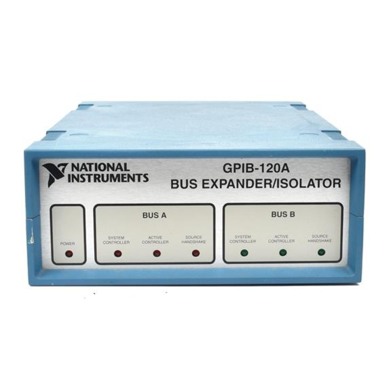
Page 16: The Gpib-120A Front Panel
Handshake state. Power On When you power on the GPIB-120A, all circuitry is cleared to an initialized state. The GPIB-120A expansion system is fully operational when you power on the GPIB-120A and your instruments are connected. Where there is GPIB activity, it is recommended that you keep at least two-thirds of the devices on both buses powered on. -
Page 17: Data Direction Control
If a Controller on Bus B conducts a parallel poll, the parallel poll detection circuitry on side A conducts a parallel poll on Bus A. The result of the parallel poll is driven on the data lines of Bus B. © National Instruments Corporation GPIB-120A User Manual... -
Page 18: Acceptable Identification Codes
Theory of Operation Acceptable Identification Codes Bus A and Bus B of the GPIB-120A are each capable of appearing as a GPIB device having the GPIB capabilities listed in Table 3-1. For a complete description of each code, consult the ANSI/IEEE Standard 488.1-1987, IEEE Standard Digital Interface for Programmable... -
Page 19: Appendix A Operation Of The Gpib
IEEE 488. The versatility of the system prompted the name General Purpose Interface Bus. National Instruments expanded the use of the GPIB among users of computers manufactured by companies other than Hewlett-Packard. National Instruments specializes both in high-... -
Page 20: Talkers, Listeners, And Controllers
Controller-In-Charge (CIC). Active control can be passed from the current CIC to an idle Controller. Only one device on the bus, the System Controller, can make itself the CIC. A GPIB interface board in a computer is usually the System Controller. GPIB-120A User Manual © National Instruments Corporation Appendix A... -
Page 21: Gpib Signals And Lines
DAV indicates when the signals on the data lines are stable (valid) and can be accepted safely by devices. The Controller drives DAV when sending commands and the Talker drives it when sending data messages. © National Instruments Corporation GPIB-120A User Manual Operation of the GPIB... -
Page 22: Interface Management Lines
The EOI line has two purposes: the Talker uses the EOI line to mark the end of a message string, and the Controller uses the EOI line to tell devices to identify their response in a parallel poll. GPIB-120A User Manual © National Instruments Corporation... -
Page 23: Physical And Electrical Characteristics
The GPIB uses negative logic with standard TTL logic levels. When DAV is true, for example, it is a TTL low level ( 0.8 V), and when DAV is false, it is a TTL high level ( 2.0 V). Figure A-1. GPIB Connector and the Signal Assignment © National Instruments Corporation DIO1 DIO5... -
Page 24: Figure A-2. Linear Configuration Of The Gpib Devices
Operation of the GPIB Appendix A Figure A-2. Linear Configuration of the GPIB Devices GPIB-120A User Manual © National Instruments Corporation... -
Page 25: Figure A-3. Star Configuration Of The Gpib Devices
Appendix A Operation of the GPIB Figure A-3. Star Configuration of the GPIB Devices © National Instruments Corporation GPIB-120A User Manual... -
Page 26: Configuration Restrictions: The Role Of Expanders And Extenders
National Instruments. The GPIB-120A is a high-speed bus expander which allows up to 14 additional devices to be connected to the bus and 20 m of cable to be added to the system. In addition, the two connected GPIBs are optically isolated to prevent ground loop and noise problems. -
Page 27: Appendix B Specifications
Appendix B Specifications This appendix lists the specifications of the GPIB-120A. Configuration Loading per expansion GPIB driver output circuit and T1 timing of source device Note: T1 is the data settling time (DIO valid to DAV) and varies according to the type of drivers and the system configuration used. -
Page 28: Table B-3. Electrical Characteristics
Operating temperature Humidity Characteristic Case style Case size Case material GPIB-120A User Manual Table B-3. Electrical Characteristics 60 V operating 1600 V breakdown 90 to 130 VAC, 235 mA, (250 mA, 250 V, slow blow), 50 to 60 Hz or... -
Page 29: Appendix C Multiline Interface Messages
These multiline interface messages are sent and received with ATN TRUE. For more information on these messages, refer to the ANSI/IEEE Standard 488.1-1987, IEEE Standard Digital Interface for Programmable Instrumentation. © National Instruments Corporation GPIB-120A User Manual... - Page 30 Multiline Interface Messages ASCII Message Definitions Device Clear Group Execute Trigger Go To Local Local Lockout My Listen Address GPIB-120A User Manual My Secondary Address My Talk Address Parallel Poll Configure Parallel Poll Disable Appendix C ASCII Msg MLA0 MLA1 "...
- Page 31 Appendix C Multiline Interface Messages Dec ASCII Parallel Poll Enable Parallel Poll Unconfigure Selected Device Clear Serial Poll Disable © National Instruments Corporation MTA0 MTA1 MTA2 MTA3 MTA4 MTA5 MTA6 MTA7 MTA8 MTA9 MTA10 MTA11 MTA12 MTA13 MTA14 MTA15 MTA16...
-
Page 32: Appendix D Customer Communication
Filling out a copy of the Technical Support Form before contacting National Instruments helps us help you better and faster. National Instruments provides comprehensive technical assistance around the world. In the U.S. and Canada, applications engineers are available Monday through Friday from 8:00 a.m. to 6:00 p.m. -
Page 33: Technical Support Form
National Instruments for technical support helps our applications engineers answer your questions more efficiently. If you are using any National Instruments hardware or software products related to this problem, include the configuration forms from their user manuals. Include additional pages if necessary. -
Page 34: Other Products
National Instruments Products • GPIB Software Revision Number on Disk • Programming Language Interface Revision • Types of National Instruments GPIB boards installed in your computer and their respective hardware settings: Board Type Other Products • Computer Make and Model •... -
Page 35: Documentation Comment Form
Documentation Comment Form National Instruments encourages you to comment on the documentation supplied with our products. This information helps us provide quality products to meet your needs. Title: GPIB-120A User Manual Edition Date: October 1994 Part Number: 370893A-01 Please comment on the completeness, clarity, and organization of the manual. - Page 36 International Standards Organization light-emitting diode meters megabytes of memory NDAC Not Data Accepted NRFD Not Ready For Data random-access memory Remote Enable seconds Service Request transistor-transistor logic volts volt amperes volts alternating current © National Instruments Corporation Value GPIB-120A User Manual...
Need help?
Do you have a question about the GPIB-120A and is the answer not in the manual?
Questions and answers