
Related Manuals for Nauticam NA-D810


Summary of Contents for Nauticam NA-D810
- Page 2 Thank you for your purchase of a NAUTICAM digital camera housing. At NAUTICAM, we pride ourselves on the ability to recognise the requirements of professional as well as amateur underwater photographers and fulfill them through the innovative designs of our products. We strive to achieve a high level of user-friendliness by allowing stress-free installation and easy operation of all important functions of the camera.
- Page 3 Please note that this warranty only applies when the product is purchased in the territory where the service centre is located. NAUTICAM accepts no liability for any damage to and defects in the housing caused by improper use and/or poor maintenance; it is the responsibility of the owner to carefully follow the instructions in our manuals.
- Page 4 1. NA-D810 housing 2. Instruction manual 3. Spare silicone rubber main o-ring 4. O-ring remover 5. CR2450 battery (for moisture alarm) 6. Lubricant 7. Set of Allen keys 8. M14 plug 9. M16 to M14 step down adaptor for electrical bulkhead...
- Page 5 O-ring(s). 2. Do not use lubricants from other brands with the silicone rubber O-ring on this housing, only use the lubricant provided by NAUTICAM. 3. Discontinue use immediately should you notice any leakage. 4. Store the housing in a robust, shock-proof container during transportation;...
- Page 6 Specifications Identification of Parts Opening and Closing the Housing Preparation of the Housing Installing the Camera Mounting the Port Changing the Viewfinder Care and Maintenance...
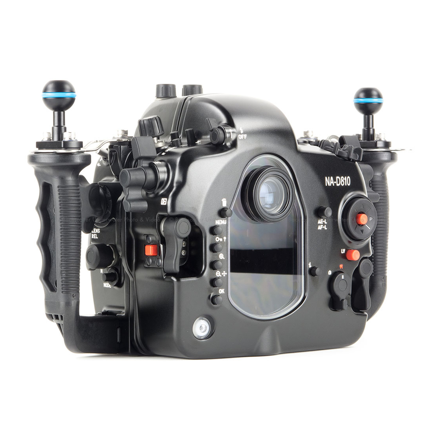
- Page 7 Housing body: Aluminium alloy Surface treatment: Hard anodised Construction Display window: Abrasion resistant polycarbonate Grip handles: Polycarbonate and rubber Width: 350 mm Dimensions Height: 208 mm (with handles) Depth: 134 mm Weight 2.96kg (with handles and ball mounts) Buoyancy Slightly negative Depth rating 100 metres Moisture alarm:...
- Page 8 Optical bulkhead for strobe On/Off control knob connections x 2 Grip handle x 2 Port alignment index Port lock/release lever...
- Page 9 M16 accessory port Mode button Main command dial M5/ M10 threaded hole Movie record lever Shutter release lever AF-ON lever Sub-command dial Exposure compensation lever Pv lever Info lever Fn lever...
- Page 10 Delete button Housing lock (R) Menu button Housing lock safety button (R) Protect/Help button Live view selector lever Housing lock (L) i button Housing lock safety button (L) Multi selector Playback zoom in button Up selection button Thumbnail/Playback zoom out Left selection button button OK button...
- Page 11 Bracketing button Flash Off lever M16 optional accessory port Release mode knob Flash pop-up/ flash M5/ M10 threaded hole compensation button Zoom/ focus gear ISO sensitivity lever disengagement lever Zoom/focus knob Playback lever Lens release button QUAL button Focus mode selection knob Metering button AF-mode button White balance button...
- Page 12 Shooting Tips 1. By setting the “Release Button to Use Dial” function of the D800 camera to Yes allows adjustments which are normally made by holding down a button and rotating a command dial to be made by rotating the command dial after the button is pressed and released.
- Page 13 1. Always open and close the housing with the front facing down, place the housing on a flat surface or in your lap. 2. When closing, make sure there is nothing caught between the closing surfaces of the two halves of the housing. 3.
- Page 14 1. After verifying that the main O-ring is in good condition, lightly coat it with the lubricant provided. 2. Make sure the O-ring groove located in the front part of the housing is free from any foreign material; the groove can be cleaned with the aid of a microfiber cloth.
- Page 15 iii. Insert the 5-pin bulkhead through the threaded hole. Tighten the 5-pin bulkhead with a spanner. Connect the 5-pin bulkhead to the accessory shoe plug. Slide the accessory shoe plug of the housing into the accessory shoe of the camera.
- Page 16 6. Setting up the moisture alarm: Install the CR2450 battery provided into the battery compartment inside the rear housing. To remove the battery, use a small flat- head screwdriver to lift up the battery as shown. Switch the alarm on. The LED light will turn blue for five seconds indicating the battery is normal.
- Page 17 (Optional) Vacuum valve can be attached to the housing via one of the accessory port for conducting a vacuum seal test. Please refer to the manual of the vacuum valve for more details of the operation. LED status identification: On start up: LED indicator Status Steady "Blue"...
- Page 18 To reset when changing port/lens: 1. Release vacuum by turning the vacuum release ring anti-clockwise. 2. Remove the port and lens from the housing and camera. 3. Press the BLUE button once to reset the system. The LED light will turn blue for five seconds then it goes into flashing blue light standby mode.
- Page 19 1. Turn the locking lever on the tray 2. Remove the camera saddle from of the housing to the “open” the housing. position. 3. Pull the sliding bar on the saddle 4. Align the pin on the saddle with to its outward position. the opening in the bottom of the camera as indicated in the diagram.
- Page 20 Attach the saddle to the camera 6. After ensuring the C/S/M activator by tightening the screw to the on the sliding bar aligns correctly tripod socket of the camera with with the focus mode selector of a screwdriver or a coin. the camera, push the sliding bar to its inward position.
- Page 21 10. Lock the camera into place by Make sure the Release mode turning the locking lever to knob is in upwards position the “lock” position. before aligning the rear housing with the front housing. Push it down when the housing is closed to gain access to the release mode dial.
- Page 22 Please refer to the NAUTICAM port system chart for a range of compatible ports; note that extension rings may be needed for certain lenses and adaptors are available for the attachment of ports of other manufacturers. To remove housing cap: 1.
- Page 23 To mount port: 5. Verify that the port opening of 4. Remove the O-ring from the port, the housing is clean and free from inspect for any damage and foreign material. lightly coat it with the provided lubricant before placing it back into its groove.
- Page 24 In order that users can change to a preferred viewfinder easily, the 0.66X viewfinder which comes with this housing is designed so that it can be removed and re-installed by following the simple steps described below. To remove the viewfinder: 1.
- Page 25 O-ring with the provided lubricant before reinstalling it in the groove. A damaged O-ring should be discarded immediately and replaced only with one that is provided by NAUTICAM. 4. Replace the main O-ring annually.
Need help?
Do you have a question about the NA-D810 and is the answer not in the manual?
Questions and answers