Beta X-Trainer 300 2T User Manual
Hide thumbs
Also See for X-Trainer 300 2T:
- Handbook (64 pages) ,
- User manual (82 pages) ,
- Manual (516 pages)
Table of Contents
Advertisement
Quick Links
X-TRAINER 300 2T
Thanks for you preference, and have a good time! This hand-
book contains the information you need to properly operate and
maintain your motorcycle.
The data, specifi cations and images shown in this manual does not constitute
an engagement on the part of BETAMOTOR S.p.A. BETAMOTOR reserves
the right to make any changes and improvements to its models at any mo-
ment and without notice.
Code 036440010 000
GB
1
Advertisement
Chapters
Table of Contents
Troubleshooting

Related Manuals for Beta X-Trainer 300 2T


Summary of Contents for Beta X-Trainer 300 2T
- Page 1 X-TRAINER 300 2T Thanks for you preference, and have a good time! This hand- book contains the information you need to properly operate and maintain your motorcycle. The data, specifi cations and images shown in this manual does not constitute an engagement on the part of BETAMOTOR S.p.A.
- Page 2 • check that the plastics are properly fastened • engine bolts • shock absorber bolts/swingarm • wheel hubs/spokes • rear frame • pipe connections • tensioning the chain IMPORTANT For any servicing requirements, please get in contact with Beta- motor’s authorized service network.
-
Page 3: Table Of Contents
CONTENTS Operating instructions ................5 Ecologic guide ..................5 Riding safety ..................6 CHAPTER 1 GENERAL INFORMATION ..........7 Vehicle identifi cation data ............... 8 Tools kit ....................8 Familiarizing with the vehicle..............9 Specifi cations ..................10 Electrical system ................... 14 Recommended lubricants and liquid ............ - Page 4 Clutch control ..................54 Check and adjusting of steering play ............56 Front wheel ..................57 Tyres....................58 Fork ....................58 Chain ....................59 Headlight .................... 61 Replacing the headlight bulbs ..............61 Tail light ....................61 Battery ....................62 Fuses ....................
-
Page 5: Operating Instructions
OPERATING INSTRUCTIONS • The vehicle must be accompanied by: number-plate, registration document, tax disc and insurance. • Any modifi cations of the engine or other parts are punishable by severe sanctions including the confi scation of the vehicle. • Do not sit on the vehicle when it is on its stand. •... -
Page 6: Riding Safety
RIDING SAFETY • Observe the Highway Code. • Always wear approved personal protective equipment. • Always ride with the low beam on. • Always keep the crash helmet visor clean. • Avoid wearing garments with hanging ends. • Do not keep sharp or brittle objects in your pockets while riding. •... -
Page 7: Chapter 1 General Information
CHAPTER 1 GENERAL INFORMATION CONTENTS Vehicle identifi cation data ............... 8 Frame identifi cation ................8 Engine identifi cation ................8 Tools kit ....................8 Familiarizing with the vehicle..............9 Main parts: ..................9 Specifi cations ..................10 Weight ................... 10 Dimensions .................. -
Page 8: Vehicle Identifi Cation Data
VEHICLE IDENTIFICATION DATA FRAME IDENTIFICATION Frame identifi cation data A are stamped on the right side of the steering head tube. ENGINE IDENTIFICATION Engine identifi cation data B are stamped in the area shown in the fi gure. TOOLS KIT The following items are supplied as stand- ard: operation and maintenance manual, tool kit. -
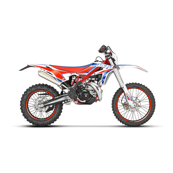
Page 9: Familiarizing With The Vehicle
FAMILIARIZING WITH THE VEHICLE MAIN PARTS: 1 - Fuel tank 10 - Lower bumper 17 - Rear side panel 2 - Tank cap (Bumper kit) 18 - Fork covers 3 - Silencer 11 - Saddle 19 - Rear mudguard 4 - Rear shock absorber 12 - Engine 5 - Headlight 13 - Front mudguard... -
Page 10: Specifi Cations
SPECIFICATIONS WEIGHT Dry weight ..........99 kg (front 48 Kg; rear 51 Kg) DIMENSIONS maximum length ................. 2157 mm maximum width ................802 mm overall height ................1245 mm wheelbase................. 1467 mm saddle height ................910 mm ground clearance ................. 320 mm footrest height ................ -
Page 11: Front Suspension
FRONT SUSPENSION Hydraulic fork USD (shafts Ø43 mm) Spring ....................K 8 Oil type ....see table “Recommended lubricants and liquids”, page 16 Oil quantity ...................500 ml Spring preload register ............completely open Rebound clicks (from completely closed) ..........15 Wheel travel................ -
Page 12: Engine
ENGINE Type ..........Single-cylinder, 2-stroke, liquid cooled and electric start Bore x stroke ................. 72 x 72 mm Displacement (cm ) ..............293,1 cm Compression ratio ................11,3:1 Fuel system ..........carburettor with electronic mixer Carburettor X-TRAINER 300 Version Certif. Competition* Carburettor type PWK 36S AG Main jet Slow jet... - Page 13 Gearchange Version X-TRAINER 300 Primary drive 28/70 Gear ratio 1 gear 12/31 Gear ratio 2 gear 15/28 Gear ratio 3 gear 19/28 Gear ratio 4 gear 20/24 Gear ratio 5 gear 27/27 Gear ratio 6 gear 28/24 Certif. Competition* Final drive 15/45 13/51 * - Such modifi...
-
Page 14: Electrical System
ELECTRICAL SYSTEM ELECTRICAL DIAGRAM Key to colours Bi = White Ve = Green Ma = Brown Vi = Purple Bl = Blue Ne = Black Gi = Yellow Rs = Red Ar = Orange Az = Sky-blue Ro = Pink Gr = Grey... -
Page 15: Legend Electrical Diagram
LEGEND ELECTRICAL DIAGRAM RIGHT-HAND FRONT TURN INDICATOR 12V 6W FRONT BRAKE LIGHT BUTTON START BUTTON WHEEL REVOLUTION SENSOR TURN INDICATORS WARNING LIGHT OIL RESERVE WARNING LIGHT DASHBOARD HEADLIGHT TELL TALE LAMP MIXER DIAGNOSIS WARNING LIGHT ENGINE STOP BUTTON HORN BUTTON HEADLIGHT SELECTOR TURN SIGNAL LAMPS SWITCH LEFT-HAND CONTROL GROUP... -
Page 16: Recommended Lubricants And Liquid
Oil Recommendations 2016 RR & Xtrainer 2 Stroke Models: (Models WITH Oil Injection) Injection Oil: Motul 710 Transmission Oil Motul Transoil Expert 10w40 Brake Fluid Motul RBF 600 Coolant/Antifreeze Motul Motocool Expert Fork Oil Motul Factory Line 5 wt. Air Filter Oil Motul Air Filter Oil Air Filter Cleaner Motul Air Filter Clean... -
Page 17: Chapter 2 Operation
CHAPTER 2 OPERATION CONTENTS Main parts ..................18 Fuel tank cup .................. 18 Fuel cock ..................18 Starter .................... 19 Mixer oil tank cap ................19 Clutch lever ..................19 LH switch ..................20 Starter button .................. 20 Front brake lever and gas control ............20 Gear change lever................ -
Page 18: Main Parts
MAIN PARTS FUEL TANK CUP To open the fuel tank cap, turn it anticlock- wise. To close the fuel tank cap, set it on the tank and screw it clockwise. FUEL COCK Fuel cock has three positions: OFF: fuel supply closed. Fuel cannot pass from the tank to the carburettor. -
Page 19: Starter
STARTER The starter lever is located on the carbu- rettor. To operate the choke pull it upward. MIXER OIL TANK CAP The mixer oil tank cap is located under the saddle To gain access remove the saddle (page 70). To open the fuel tank cap turn it anticlock- wise. -
Page 20: Lh Switch
LH SWITCH The dip and service switch is located on the left side of the handlebar and is com- posed as follows: 1 - Horn button; 2 - Dip switch: only parking lights; parking lights and high beam; parking lights and low beam; 3 - Shut-down : press the button until the engine stops;... -
Page 21: Gear Change Lever
GEAR CHANGE LEVER Gear change lever is fi tted to the left side of the engine. The positions corresponding to the different gears are shown in the fi gure. BRAKE PEDAL Brake pedal is located in front of the right- hand footrest. -
Page 22: Steering Lock
STEERING LOCK To activate the steering lock: - turn the handlebar counter-clockwise; - push the key and turn counter-clockwise; Remove the key from this position. The engine can not be started. To deactivate the steering lock: - turn the key clockwise; - turn the handlebar clockwise;... -
Page 23: Digital Rpm Indicator Operating Instructions
DIGITAL RPM INDICATOR OPERATING INSTRUCTIONS Contents 1 GENERAL SPECIFICATIONS AND GENERAL INFORMATIONS 1.1 General specifi cations 1.2 General informations 2 SETTING THE PARAMETERS 2.1 Setup sequence 2.1.1 Selecting the unit of measure 2.1.2 Selecting the wheel size 2.1.3 Selecting the clock format 2.1.4 Setting the Time 2.1.5 Selecting the maintenance memo 3 SCREENS... - Page 24 When using supplied power with the engine on: • The back-lighting is on permanently when the engine is running. Using only the internal battery: • With the LO symbol, the backlighting will not switch on. The symbol appears when the battery voltage is lower than 2.45V. Reset Button: Using the Reset button, located on the back of the instrument, all travel data will be deleted, including date and time.
- Page 25 2.1 SETUP SEQUENCE Select unit of measure Wheel size Clock format Setting the Time Maintenance reminder 2.1.1 Selecting the unit of measure (Km/h or M/h): TO SELECT THE UNIT OF MEASURE (Km/h or M/h), PRESS THE RIGHT OR LEFT BUTTON. WAIT 5 SECONDS TO PROCEED TO THE NEXT SETTING.
- Page 26 3 SCREENS Switching between 3 normal modes All of the information that the instrument is capable of providing is displayed on one of these 3 screens. The instrument will stay on the set screen until a button is pressed to switch to another screen.
- Page 27 5 SPEEDOMETER Speed The speed is displayed in the centre of screens 1 or 2 and can range from 0 to 399.9 km/h or M/h. The unit of measure (km/h or M/h) appears next to the speed reading. Maximum (Max) and Average (AVG) speed The Maximum (MAX) or Average (AVG) speeds are displayed on screen 3 to the left of the display.
- Page 28 Travelled distance (DST) The travelled distance can range from 0 to 9999.9 miles or kilometers and appears on the right side of screen 1. To clear the travelled distance, hold the right button down for 5 seconds. Note: you must be on screen 1 to clear the travelled distance. Travelled distance 2 (DST 2) Travelled distance 2 can range from 0 to 9999.9 miles or kilometers and appears on the right side of screen 2.
-
Page 29: Checks Before And After Use
7.3 Mixer system indicator light 3 When you start the vehicle, the system performs a diagnosis check, while the indica- tor lights for 10 seconds. If the indicator comes on during normal operation, it tndicates a fault in the mixer system. -
Page 30: Refuelling
REFUELLING Use unleaded petrol. Fuel tank capacity is shown on page 10. To refuel open the tank cap (page 18). After refuelling, screw the cap back and tighten securely. WARNING The refuelling should be performed with the engine off. WARNING Fire hazard. -
Page 31: Oil Mixer Refuelling
OIL MIXER REFUELLING To refuel open the tank cap (page 19). Fuel tank capacity is shown on page 10. After refuelling, screw the cap back and tighten securely. Use the oil indicated on page 16 in the “Recommended lubricants and liquids” table. -
Page 33: Chapter 3 Adjustments
CHAPTER 3 ADJUSTMENTS INDICE ARGOMENTI Key to symbols..................34 Brakes ....................34 Front brake ..................34 Rear brake ..................34 Clutch ....................34 Adjustment of gas clearance ..............35 Handlebar adjustment ................35 U-bolt position adjustment ..............35 Adjustment of the handlebar position ..........36 Adjusting fork .................. -
Page 34: Key To Symbols
KEY TO SYMBOLS Tightening torque Threadlocker Medium BRAKES FRONT BRAKE The front brake is disk type with hydraulic control. The home position of brake lever 2 can be adjusted by means of screw 1. REAR BRAKE The home position of brake pedal 3 can be altered by turning adjusting screw 5 af- ter loosening the counternut located under dust cap 4. -
Page 35: Adjustment Of Gas Clearance
ADJUSTMENT OF GAS CLEARANCE The throttle control cable should always have a 3-5 mm play. In addition, the idle speed should not change when the han- dlebars are fully rotated to the left or right. Push back protective cap 1. Loosen coun- ternut 2 and turn adjusting screw 3. -
Page 36: Adjusting Fork
Apply the handlebar. Apply the top u-bolt. Refi t the screws 6. Tighten to the torque indicated. 25Nm ADJUSTMENT OF THE HANDLEBAR POSITION The handlebar can be adjusted by rotating it back and forth. To adjust the handlebar loosen screws 1. Position the handlebar according to re- quirements. -
Page 37: Shock Absorber
SHOCK ABSORBER ADJUSTING THE REBOUND DAMPER Turn screw A to adjust the hydraulic re- bound damper. For adjustment refer to the table on the side. Increase Decrease For standard setting, refer to page 11. braking effect braking effect ADJUSTING THE HYDRAULIC COMPRESSION DAMPER Turn knob A to adjust the hydraulic com- pression damper. -
Page 38: Adjusting The Spring Preload
ADJUSTING THE SPRING PRELOAD To adjust the spring preload, use the pro- cedure described below: Loosen the locking dowel A. Turn the ring nut B until you reach the desired preload. Lock the locking dowel A. For standard setting, refer to page 11. Note: for movement of the rings use a specifi... -
Page 39: Chapter 4 Checks And Maintenance
CHAPTER 4 CHECKS AND MAINTENANCE CONTENTS Engine oil .................... 40 Check the level ................40 Replacement ................... 40 Liquid coolant ..................41 Check the level ................41 Replacement ................... 42 Air fi lter cleaning ................44 Air fi lter ....................44 Removing and installing air fi... -
Page 40: Engine Oil
ENGINE OIL CHECK THE LEVEL Hold the vehicle upright. Position the drive on a fl at base ensuring stability. Remove the inspection cap 1. The oil level must arrive to the lower edge of check hole. Otherwise restore the oil level through plug 2. -
Page 41: Liquid Coolant
Screw on fi ller cap 1 again. WARNING: Hot oil can cause severe burns! Wear appropriate protective clothing and protection gloves. In case of burns, rinse immediately with lukewarm water the affected area. WARNING: Dispose of used oil in compliance with the regulations in force. -
Page 42: Replacement
WARNING: Wear appropriate protective clothing and protection gloves. Avoid any direct contact of the coolant with skin, eyes or clothing. If this happens: - with the eyes, rinse immediately with plenty of water and seek medical advice. - with skin, Immediately clean contaminat- ed areas with soap and water Change clothing that is contaminated with cool- ant. - Page 43 - Unscrew drain screw 3. - Proceed to fi lling. - Reapply the loading cap and the bleed- ing screw. The amounts of liquid are shown on page Use the liquid indicated on page 16 in the “Recommended lubricants and liquids” table.
-
Page 44: Air Fi Lter
AIR FILTER Check after every ride. REMOVING AND INSTALLING AIR FILTER To access the fi lter is necessary: •Remove the saddle (page 70). •Pull the cover air fi lter (page 71). •Release fi lter fastener 1. •Pull out air fi lter 2. WARNING: After every intervention, check that nothing has been left inside the fi... -
Page 45: Spark Plug
NOTE: If the fi lter is damaged, replace it immediately. To replace, contact authorised Betamotor customer service. WARNING: Never use the vehicle if the air fi lter is not in place. The infi ltration of dust and dirt can cause damage and considerable wear. WARNING: After every intervention, check that nothing has been left inside the fi... -
Page 46: Carburettor
CARBURETTOR DRAINING THE CARBURETTOR FLOAT CHAMBER If the carburettor tank needs to be emptied, proceed as described. Remove the chain protection 1, close the tank tap and put a cloth under the carbu- rettor, so that you can collect the running out fuel. -
Page 47: Checking The Fl Oat Level
WARNING: Risk of poisoning! Fuel is poisonous liquid and a health hazard. Wear appropriate protective clothing and protection gloves. Fuel must not come into contact with the skin, eyes, and clothing. Do not breathe in the fuel vapours. If contact occurs with the eyes, rinse immediately with plenty of water and seek medical advice. -
Page 48: Front Brake
FRONT BRAKE CHECK THE LEVEL OF THE FRONT BRAKE FLUID Check the level of the brake fl uid through sight A. The level of the fl uid should never fall below the mark in the sight. RESTORING THE LEVEL OF THE FRONT BRAKE FLUID To restore the level of the brake fl... -
Page 49: Bleeding The Front Brake
BLEEDING THE FRONT BRAKE To bleed air from the front brake circuit, proceed as follows: •Remove the rubber cap 1 from the valve 2. •Open the sump cap. •Place one end of a small transparent tube into the valve 2, and the other end inside a container. -
Page 50: Front Brake Lining Control
FRONT BRAKE LINING CONTROL In order to verify the wear condition of front brake is enough to view the caliper from the bottom, where is possible to glimpse the brake lining tails which will have to show a brake of 2 mm in thickness. If the stratum is lesser let’s start replacing them. -
Page 51: Rear Brake
REAR BRAKE CHECK THE LEVEL OF THE REAR BRAKE FLUID Check the level of the brake fl uid through sight A. The level of the fl uid should never fall below the mark in the sight. RESTORING THE LEVEL OF THE REAR BRAKE FLUID To restore the oil level, top up by means of oil fi... -
Page 52: Bleeding The Rear Brake
BLEEDING THE REAR BRAKE To bleed air from the rear brake circuit, proceed as follows: •Remove the rubber cap 1 from the valve 2. •Open the sump cap. •Place one end of a small transparent tube into the valve 2, and the other end inside a container. -
Page 53: Front Brake Lining Control
FRONT BRAKE LINING CONTROL In order to verify the wear condition of front brake is enough to view the caliper from above, where is possible to glimpse the brake lining tails which will have to show a brake of 2 mm in thickness. If the stratum is lesser let’s start replacing them. -
Page 54: Clutch Control
CLUTCH CONTROL CHECK THE LEVEL To check the oil level in the clutch pump, fi rst remove cover 2. Remove the two screws 1 and take off cover 1 together with the rubber bellows. With the clutch pump in a horizontal posi- tion, the level of the oil should be 5 mm below the upper rim. -
Page 55: Bleeding
BLEEDING To bleed air from the clutch pump, proceed as follows: • Remove the rubber cap 1 from the valve 2. • Open the sump cap. • Place one end of a small transparent tube into the valve 2, and the other end inside a container. -
Page 56: Check And Adjusting Of Steering Play
CHECK AND ADJUSTING OF STEERING PLAY Periodically check the play in the steering sleeve by moving the fork back and forth as shown in the fi gure. Whenever you feel play, adjust as described below: - Loosen the screws 1 - Loosen the screw 2 - Reduce the play by turning nut 3 Tighten the screws to the prescribed torque... -
Page 57: Front Wheel
FRONT WHEEL TIGHTENING Following removal of the wheel: • Compress and release the fork 3-4 times. • Tighten the wheel bolt and the screws of the foot-leg. 20Nm 50Nm... -
Page 58: Tyres
FORK 17Nm To maintenance refer at an authorized service center Betamotor. To check the tightening torques see as shown in the fi gure. WARNING: Tightening of the screws should be carried out by adjusting the torque wrench to the stability torque with repeated tightening until stability torque has been achieved. -
Page 59: Chain
CHAIN Checking the drive chain periodically to ensure longer chain life. Always keep it lubricated and clean of deposited dirt. Take special care in preventing the lubri- cant from coming into contact with the rear tyre or brake disc, otherwise the tyre grip and the action of the brake would be greatly reduced, making it very diffi... -
Page 60: Check For Chain Wear
• Loosen counternuts A on either side of the fork. • Turn adjusting screws B on either side until the desired chain tension is obtained. • Tighten counternuts A on either side of the fork. • Tighten the pin 1 to the torque indicated. 130Nm CHECK FOR CHAIN WEAR 10 -15 Kg... -
Page 61: Headlight
HEADLIGHT Keep the headlight glass clean at all times (see page 65). Periodically check the correct angle of the light beam. REPLACING THE HEADLIGHT BULBS Remove the fi xing screws and move for- ward the lamp holder front cowl. Carefully remove the headlight bulb 1 together with lamp holder. -
Page 62: Battery
BATTERY Battery is located under the saddle and requires no maintenance. Keep the battery terminals clean. If neces- sary, protect them with a thin fi lm of acid- free grease. BATTERY REMOVAL AND ASSEMBLY Remove the saddle (page 70). Release the rubber band. FIRST disconnect the negative connector (black) from negative (-) pole and THEN positive connector (black) from negative... -
Page 63: Inactivity
INACTIVITY If the vehicle is not going to be used for a long time, remove the battery and charge it every 15 days using a suitable charger. Store the battery in a dry place at a tem- perature of 5 to 35°C and out of the reach of children. -
Page 64: Fuses
FUSES To access the fuse, remove the saddle (page 70). In the case of blown fuse, the vehicle will not start/stop: Three spare fuses comes with the kit ac- companying the vehicle. A blown fuse should only be replaced with another of the same type. -
Page 65: Cleaning The Vehicle
CLEANING THE VEHICLE WARNING: Do not clean your vehicle with a high-pressure device with a strong jet of water. Excessive pressure can reach electrical components, connectors, fl exible cables, bearings, etc and can damage or destroy them. WARNING: Wash motorbikes frequently that are used near the sea (salty air) and on roads subject to salt spreading in winter. -
Page 66: Prolonged Inactivity
PROLONGED INACTIVITY A few simple operations should be performed to keep the vehicle in good condition whenever it is to remain inactive for a long period (e.g. during the winter): • Thoroughly clean the vehicle. • Reduce the tyre pressures by approximately 30 percent, and if possible raise the tyres off the ground. -
Page 67: Scheduled Maintenance Vehicle
SCHEDULED MAINTENANCE VEHICLE Engine Gear and clutch oil Spark plug Head screws Engine clamping screws * Kick start and gearchange lever screws Spark plug cap Coated clutch disks Clutch springs length Clutch/bell hub Gearbox bearing (drive shaft side) Cylinder Piston and segments Connecting rod Drive shaft bearings Surface appearance of the gearbox... - Page 68 Brakes Liquid level, pads thickness Disc thickness Pipe tightness Idle travel levers and drives sliding Cycling Shock absorber and telescopic fork Fork cover Bearings of stearing Bolts Wheels Wheel spokes and rim coaxiality Tyres (wear and pressure) Bearings clearance Check (Clean, adjust, lubricate, replace as necessary) Replace/renew Adjust Clean...
-
Page 69: Chapter 5 Replacements
CHAPTER 5 REPLACEMENTS CONTENTS Removal and refi tting of the saddle............70 Removing and installing air fi lter cover panel ........... 71... -
Page 70: Removal And Refi Tting Of The Saddle
REMOVAL AND REFITTING OF THE SADDLE Press button 1. Remove the saddle towards the rear of the motorcycle. To re-assemble insert the cavity 1 of the saddle in slot 2. Press the saddle down in the middle and at the same time, push it forwards until the bayonet joint engages in its seat. -
Page 71: Removing And Installing Air Fi Lter Cover Panel
WARNING Make sure the bayonet joint 3 is fi rmly inserted into the button lock. REMOVING AND INSTALLING AIR FILTER COVER PANEL Remove the saddle (page 70). Grab the side panel in the front side and pull out. To refi t insert the tabs 1 into their slots. Slide the side panel toward the vehicle. -
Page 73: Chapter 6 Troubleshooting
CHAPTER 6 TROUBLESHOOTING CONTENTS Troubleshooting ................... 74 Alphabetical index ................75... -
Page 74: Troubleshooting
TROUBLESHOOTING PROBLEM CAUSE REMEDY Engine does not start - Fuel system clogged (fuel lines, fuel Contact authorised BETAMOTOR tank, fuel cock) customer service - Air fi lter dirty Check the air fi lter - No current supplied to spark plug Clean or replace the spark plug. - Page 75 ALPHABETICAL INDEX Adjusting fork ..................36 Adjustment of gas clearance ..............35 Air fi lter ....................44 Battery ....................62 Brakes ....................34 Carburettor ..................46 Chain ....................59 Check and adjusting of steering play ............56 Checks before and after use ..............29 Cleaning the vehicle ................
- Page 76 Oil mixer refuelling ................31 Operating instructions ................5 Prolonged inactivity ................66 Rear brake ..................51 Recommended lubricants and liquid ............16 Refuelling .................... 30 Removal and refi tting of the saddle............70 Removing and installing air fi lter cover panel ........... 71 Replacing the headlight bulbs ..............
Need help?
Do you have a question about the X-Trainer 300 2T and is the answer not in the manual?
Questions and answers