Table of Contents
Advertisement
Quick Links
Visit our website at
www.MillerWelds.com
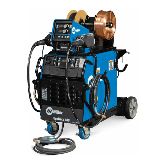
PipeWorx 400
Welding System
(230/460 And 575 Volt Models)
OM-236 891R
2013−07
Processes
MIG (GMAW) and Pulsed MIG
(GMAW-P) Welding
TIG (GTAW) Welding
Flux Cored (FCAW) Welding
Stick (SMAW) Welding
Multiprocess Welding
Description
Arc Welding Power Source
Wire Feeder
File: MIG (GMAW)
Advertisement
Table of Contents
Troubleshooting

Related Manuals for Miller PipeWorx 400


Summary of Contents for Miller PipeWorx 400
- Page 1 MIG (GMAW) and Pulsed MIG (GMAW-P) Welding TIG (GTAW) Welding Flux Cored (FCAW) Welding Stick (SMAW) Welding Multiprocess Welding Description Arc Welding Power Source Wire Feeder PipeWorx 400 Welding System (230/460 And 575 Volt Models) File: MIG (GMAW) Visit our website at www.MillerWelds.com...
- Page 2 We know you don’t have time to do it any other way. That’s why when Niels Miller first started building arc welders in 1929, he made sure his products offered long-lasting value and superior quality.
-
Page 3: Table Of Contents
........5-16. Weld Output Terminals And Selecting Cable Sizes* Recommended For PipeWorx 400 . - Page 4 ............6-14. Basic Parameters For PipeWorx 400 .
-
Page 5: Section 1 − Safety Precautions - Read Before Using
SECTION 1 − SAFETY PRECAUTIONS - READ BEFORE USING som 2011−10 Protect yourself and others from injury — read, follow, and save these important safety precautions and operating instructions. 1-1. Symbol Usage DANGER! − Indicates a hazardous situation which, if Indicates special instructions. - Page 6 D Remove stick electrode from holder or cut off welding wire at FUMES AND GASES can be hazardous. contact tip when not in use. D Wear oil-free protective garments such as leather gloves, heavy Welding produces fumes and gases. Breathing shirt, cuffless trousers, high shoes, and a cap.
-
Page 7: Additional Symbols For Installation, Operation, And Maintenance
1-3. Additional Symbols For Installation, Operation, And Maintenance FIRE OR EXPLOSION hazard. BATTERY EXPLOSION can injure. D Do not install or place unit on, over, or near D Do not use welder to charge batteries or jump combustible surfaces. start vehicles unless it has a battery charging feature designed for this purpose. -
Page 8: California Proposition 65 Warnings
1-4. California Proposition 65 Warnings Welding or cutting equipment produces fumes or gases This product contains chemicals, including lead, known to which contain chemicals known to the State of California to the state of California to cause cancer, birth defects, or other cause birth defects and, in some cases, cancer. -
Page 9: Section 2 − Consignes De Sécurité − Lire Avant Utilisation
SECTION 2 − CONSIGNES DE SÉCURITÉ − LIRE AVANT UTILISATION fre_som_2011−10 Pour écarter les risques de blessure pour vous−même et pour autrui — lire, appliquer et ranger en lieu sûr ces consignes relatives aux précautions de sécurité et au mode opératoire. 2-1. - Page 10 Il reste une TENSION DC NON NÉGLIGEABLE dans LE SOUDAGE peut provoquer un les sources de soudage onduleur UNE FOIS incendie ou une explosion. l’alimentation coupée. Le soudage effectué sur des conteneurs fermés tels D Arrêter les convertisseurs, débrancher le courant électrique et que des réservoirs, tambours ou des conduites peut décharger les condensateurs d’alimentation selon les instructions provoquer leur éclatement.
-
Page 11: Dangers Supplémentaires En Relation Avec L'installation, Le Fonctionnement Et La Maintenance
ACCUMULATIONS LES BOUTEILLES peuvent exploser risquent de provoquer des blessures si elles sont endommagées. ou même la mort. Les bouteilles de gaz comprimé contiennent du gaz sous haute pression. Si une bouteille est D Fermer l’alimentation du gaz comprimé en cas endommagée, elle peut exploser. -
Page 12: Proposition Californienne 65 Avertissements
Les PIÈCES MOBILES peuvent RAYONNEMENT HAUTE causer des blessures. FRÉQUENCE (H.F.) risque provoquer des interférences. D Ne pas s’approcher des organes mobiles. D Ne pas s’approcher des points de coincement D Le rayonnement haute fréquence (H.F.) peut tels que des rouleaux de commande. provoquer des interférences avec les équi- pements de radio−navigation et de com- LES FILS DE SOUDAGE peuvent... -
Page 13: Principales Normes De Sécurité
2-5. Principales normes de sécurité Safety in Welding, Cutting, and Allied Processes, ANSI Standard Z49.1, Spectrum Way, Suite 100, Ontario, Canada L4W 5NS (phone: is available as a free download from the American Welding Society at 800-463-6727, website: www.csa-international.org). http://www.aws.org or purchased from Global Engineering Documents Safe Practice For Occupational And Educational Eye And Face Protec- (phone: 1-877-413-5184, website: www.global.ihs.com). - Page 14 OM-236 891 Page 10...
-
Page 15: Section 3 − Definitions
SECTION 3 − DEFINITIONS 3-1. Additional Safety Symbols And Definitions Some symbols are found only on CE products. Warning! Watch Out! There are possible hazards as shown by the symbols. Safe1 2012−05 Wear dry insulating gloves. Do not touch electrode with bare hand. Do not wear wet or damaged gloves. Safe2 2012−05 Protect yourself from electric shock by insulating yourself from work and ground. - Page 16 Disconnect input plug or power before working on machine. Safe5 2012−05 When power is applied failed parts can explode or cause other parts to explode. Safe26 2012−05 Flying pieces of parts can cause injury. Always wear a face shield when servicing unit. Safe27 2012−05 Always wear long sleeves and button your collar when servicing unit.
- Page 17 Consult rating label for input power requirements. Safe34 2012−05 Drive rolls can injure fingers. Safe32 2012−05 Welding wire and drive parts are at welding voltage during operation − keep hands and metal objects away. Safe33 2012−05 Become trained and read the instructions before working on the machine or welding.
-
Page 18: Miscellaneous Symbols And Definitions
3-2. Miscellaneous Symbols And Definitions Some symbols are found only on CE products. Direct Current Alternating Amperage Voltage (DC) Current (AC) Protective Earth Circuit Breaker (Ground) Gas Tungsten Arc Welding (GTAW) / Shielded Metal Arc High Frequency - Positive Welding (SMAW) General Tungsten Inert Gas (TIG) Welding... -
Page 19: Section 4 − Specifications
SECTION 4 − SPECIFICATIONS 4-1. Serial Number And Rating Label Location The serial number and rating information for this product is located on the front. Use rating label to determine input power requirements and/or rated output. For future reference, write serial number in space provided on back cover of this manual. 4-2. - Page 20 Source Type Speed Range Range Rating* Dimensions Single Dual Rating 24 Volts AC PipeWorx 400 50 To 780 ipm .035 To .062 in 100 Volts, IP 21 Length: 29 in. 11 Amperes (1.3 To 19.8 (0.9 To 1.6 mm) (737 mm)
-
Page 21: Mig Duty Cycle And Overheating
4-3. MIG Duty Cycle and Overheating Duty Cycle is percentage of 10 min- utes that unit can weld at rated load without overheating. If unit overheats, thermostat(s) opens, output stops, and cooling fan runs. Wait fifteen minutes for unit to cool. Reduce amperage or duty cycle before welding. -
Page 22: Section 5 − Installation
SECTION 5 − INSTALLATION 5-1. Selecting a Location Movement Do not move or operate Tipping unit where it could tip. Special installation may be required where gasoline or Location volatile liquids are present − see NEC Article 511 or CEC Section 20. -
Page 23: Remote 14 Accessory Receptacle Information
5-2. Remote 14 Accessory Receptacle Information If a remote control is connected to the Remote 14 receptacle, the unit will automatically adjust output control to a primary/secondary configuration. In this configuration, the Amperage Adjust knob on the unit becomes the primary and sets the maximum amperage output of the unit. The remote control becomes the secondary and provides an amperage range of 0 to 100% based on the Amperage Adjust knob setting. -
Page 24: Turning On Remote 14 Receptacle Control For Stick
5-3. Turning On Remote 14 Receptacle Control For Stick Turn Off welding power source, disconnect input power, and check voltage on input capacitors accord- ing to Section 7-6 before proceeding. Stick Stick When this control is active and a current/contactor control Remote Remote... -
Page 25: Changing Wire Feed Speed From Inches Per Minute (Ipm) To
5-4. Changing Wire Feed Speed From Inches Per Minute (IPM) To Meters Per Minute (MPM) Turn Off welding power source, disconnect input power, and check voltage on input capacitors accord- ing to Section 7-6 before proceeding. PipeWorx Feeder Operator Interface Board Dip Switch Remove feeder wrapper. -
Page 26: Remote 14 Wire Feeder Control Receptacle Information
5-5. Remote 14 Wire Feeder Control Receptacle Information Remote 14 Feeder Control Socket* Socket Information 8, 12 24 volts AC. Protected by supplementary protector CB2. 24 VOLTS AC 24 volts AC return. Connected to chassis common. Completes 24 volts AC power supply circuit to feeder. -
Page 27: Supplementary Protector Cb2
5-6. Supplementary Protector CB2 Supplementary Protector CB2 CB2 protects the 24 volts ac power supply to the wire feeder (see Section 5-5). Press button to reset supplementary protector. TO WIRE FEEDER TIG GAS IN MIG OUTPUT 805 298-A OM-236 891 Page 23... -
Page 28: Volts Ac Single Receptacle And Supplementary Protector
5-7. 115 Volts AC Single Receptacle RC2 And Supplementary Protector 115V 10A AC Receptacle RC2 RC2 is a designated use receptacle intended only for supplying AC power to a PipeWorx cooler. Power is available at receptacle RC2 only when the power source is on. -
Page 29: Lifting Eye On Power Source
5-8. Lifting Eye On Power Source Turn Off welding power source, disconnect input power. Lifting Eye The wire feeder allows access to the lifting eye on the power source. The entire welding system as shown with cable hangers, cooler with coolant, dual feeder, and running gear can be lifted with the lifting eye. -
Page 30: Selecting Input Voltage (230/460 Volt Models Only)
5-9. Selecting Input Voltage (230/460 Volt Models Only) Turn Off welding power source, disconnect input power, and check voltage on input capacitors accord- ing to Section 7-6 before Be sure to reinstall all four screws securing proceeding. relinking board in place. Check input voltage available at site. -
Page 31: Electrical Service Guide
5-10. Electrical Service Guide Elec Serv 2011−08 NOTICE − INCORRECT INPUT POWER can damage this welding power source. This welding power source requires a CONTINUOUS supply of input power at rated frequency(+10%) and voltage (+10%). Phase to ground voltage shall not exceed +10% of rated input voltage. Do not use a genera- tor with automatic idle device (that idles engine when no load is sensed) to supply input power to this welding power source. -
Page 32: Connecting 3-Phase Input Power
5-11. Connecting 3-Phase Input Power GND/PE Earth Ground Tools Needed: 5/16 in. Input5 2013−04 − Ref. 803 766-C / 805 146-A OM-236 891 Page 28... - Page 33 5-11. Connecting 3-Phase Input Power (Continued) Input Power Conductors (Customer Connect input conductors L1, L2, and L3 to Turn Off welding power source, and Supplied Cord) welding power source line terminals. check voltage on input capacitors according to Section 7-6 before Select size and length of conductors using Reinstall side panel on welding power source.
-
Page 34: Installing Optional Handles, Running Gear And Cooler
5-12. Installing Optional Handles, Running Gear And Cooler Turn Off welding power source, Tools Needed: disconnect input power. 1/2 in. Running Gear 234 359 Cooler Wheel 163 463 (2) Flat Washer 602 250 (4) 5/16 in. Retaining Ring 121 614 (2) Install wheels on cylinder tray as shown. -
Page 35: Assembling And Installing Cable Hanger
5-13. Assembling And Installing Cable Hanger Bracket Tube Cap (4) Cable Holder Tube (2) Install caps in tubes. Assemble cable holder tubes to bracket using supplied hardware. Place cable holder assembly on top of power source or cart and set wire feeder on cable hanger. -
Page 36: Proper Ring Terminal Connection To Volt Sense Lead
5-14. Proper Ring Terminal Connection To Volt Sense Lead If volt sense lead is cut or broken at end Jacket Center Conductor 10 ga with ring terminal, be sure that new ring ter- Insulated Tape Or Heat-Shrink minal is connected as shown. Tubing Ring Terminal 1/2 in. -
Page 37: Weld Output Terminals And Selecting Cable Sizes* Recommended For Pipeworx 400
**Weld cable size (AWG) is based on either a 4 volts or less drop or a current density of at least 300 circular mils per ampere. ( ) = mm for metric use. ***For distances longer than those shown in this guide, call a factory applications rep. at 920-735-4505 (Miller) or 1-800-332-3281 (Hobart) Ref. S-0007-G 2009−08 OM-236 891 Page 33... -
Page 38: Connecting Weld Output Cables
5-17. Connecting Weld Output Cables Do not place anything between weld cable terminal and copper bar. Tools Needed: 3/4 in. (19 mm) Incorrect Installation 803 778-B Weld Output Terminal weld output terminal and secure with nut so Turn off power before connecting to that weld cable terminal is tight against weld output terminals. -
Page 39: Typical Connection Diagram For Mig (Gmaw) Equipment With Feeder On Power Source
5-18. Typical Connection Diagram For MIG (GMAW) Equipment With Feeder On Power Source 805 144-B Gas Hose of gas hose to gas solenoid connector on Do not put feeder where welding rear of feeder or Y-hose for dual wire feeder. wire hits cylinder. -
Page 40: Typical Connection Diagram For Mig (Gmaw) Equipment With Feeder On Cart
5-19. Typical Connection Diagram For MIG (GMAW) Equipment With Feeder On Cart 805 317-B Gas Cylinder connect remaining end of gas hose to gas Do not put feeder where welding solenoid connector on rear of feeder or wire hits cylinder. Locate end of composite cable where gas Y-hose for dual wire feeder. -
Page 41: Wire Feeder Rear Panel Connections And Rotating Drive Assembly
5-20. Wire Feeder Rear Panel Connections And Rotating Drive Assembly 14-Pin Control Cable Shielding Gas Valve Fittings Requires fitting with 5/8-18 right-hand threads. Connect customer-supplied gas hose. Weld Cable Terminal Jumper Weld Cable From Right Side Drive Assembly (Dual Model Only) Weld Cable Drive Assembly Drive Assembly Rotation... -
Page 42: Gun Trigger Receptacle
5-21. Gun Trigger Receptacle Left Gun Trigger Receptacle Right Gun Trigger Receptacle RC3 (Dual Model Only) Connect gun trigger plug to appropriate receptacle on feeder. 805 154-A OM-236 891 Page 38... -
Page 43: Installing And Threading Welding Wire
5-22. Installing And Threading Welding Wire Install wire guides and Install wire spools. Adjust tension nuts so anti-wear guide. wire is taut when wire feed stops. Install drive rolls. Pressure Indicator Pressure Scale Adjust Rear Pressure Rolls Adjust Front Rolls No Wire Slip Wire Slips NONCONDUCTIVE... -
Page 44: Voltage Sensing Lead And Work Cable Connections For Multiple Welding Arcs
5-23. Voltage Sensing Lead And Work Cable Connections For Multiple Welding Arcs A. Ideal Setup 805 289-B Welding Power Source signal to the welding system. Use of this This arrangement is an ideal setup for lead is critical stable welding supporting separate voltage feedback to Composite Cable performance. - Page 45 B. Bad Setup 805 290-B Welding Power Source Workpiece across the workpiece will not be measured correctly for the voltage feedback signal. Composite Cable This arrangement is a bad setup due to Voltage feedback to the welding power sensing leads being directly in the current Work Cable sources will not be correct at either sense flow path of the welding arc.
-
Page 46: Arranging Welding Cables To Reduce Welding Circuit Inductance
5-24. Arranging Welding Cables To Reduce Welding Circuit Inductance Welding Power Source Composite Cable Work Cable Volt Sense Lead Ideal Wire Feeder Workpiece The method used to arrange cables has significant affect welding performance. As an example, Pro-Pulse and RMD welding processes can produce high welding circuit inductance depending on cable length and arrangement. -
Page 47: Typical Connection Diagram For Stick (Smaw) Equipment
5-25. Typical Connection Diagram For Stick (SMAW) Equipment Welding Power Source Work (−) Weld Cable Stick (+) Weld Cable Workpiece Electrode Holder Volt Sense Lead Attach volt sense lead to work clamp and attach work clamp as close to arc as possible. 115V 10A AC Receptacle (Cooler Power Supply Only) READ OWNER'S MANUAL... -
Page 48: Typical Connection Diagram For Two Piece Air-Cooled Tig (Gtaw) Torch
5-26. Typical Connection Diagram For Two Piece Air-Cooled TIG (GTAW) Torch (Using Gas Solenoid Inside Power Source) Welding Power Source Gas Hose TIG (−) Weld Cable Work (+) Weld Cable Workpiece TIG Torch Volt Sense Lead Remote Foot Control (Optional) Attach volt sense lead to work clamp and attach work clamp as close to arc as possible. -
Page 49: Typical Connection Diagram For One Piece Air-Cooled Tig (Gtaw) Torch
5-27. Typical Connection Diagram For One Piece Air-Cooled TIG (GTAW) Torch (Using Gas Solenoid Inside Power Source) Welding Power Source Gas Hose 237 415 (Short Black Hose Supplied With Power Source) TIG Block (Customer Supplied) TIG (−) Weld Cable Work (+) Weld Cable Workpiece TIG Torch Volt Sense Lead... -
Page 50: Typical Connection Diagram For Liquid-Cooled Tig (Gtaw) Torch
5-28. Typical Connection Diagram For Liquid-Cooled TIG (GTAW) Torch (Using Gas Solenoid Inside Power Source) Welding Power Source Gas Hose TIG Block (Customer Supplied) Coolant Out Hose 237 416 (Short Red Hose Supplied With Cooler) TIG (−) Weld Cable Coolant Return Hose Work (+) Weld Cable Workpiece TIG Torch... -
Page 51: Section 6 − Operation
Only dual shielded wire is recommended for the PipeWorx 400. A gas mixture or wire diameter selection is not required. See wire manufacturer for the recommended gas mixture. The 0.035 to 0.062 wire sizes can be used in the process. - Page 52 6-1 . Operational Terms (Continued) Pulse An advanced pulse spray transfer process suited for the fill and cap passes on pipe. The Pulse process utilizes (Pro-Pulset) constant current ramps with constant voltage control of peaks and backgrounds. Adaptive response is controlled by peak and minimum current levels.
-
Page 53: Welding Power Source Controls
6-2. Welding Power Source Controls A. Front Panel Controls 252 611-A Memory Location Buttons 1-4 12 MIG Process Type Select Button Only illuminated controls can be Stick Process Select Button 13 Wire Type Select Button changed or adjusted. Stick Electrode Type Select Button 14 Wire Diameter Select Button Memory Card Busy Indicator Ammeter Display... - Page 54 B. Memory Card Slot Memory Card Slot This is the memory card slot. A memory card can be inserted into the slot and used for storing and retrieving operator settings, providing custom MIG type weld process data, and loading firmware updates to the unit.
- Page 55 C. Memory Function Controls Memory Card Busy Indicator The memory card busy LED illuminates during the following conditions: storage/retrieval of operator settings, usage of custom MIG type weld process, and firmware upgrades. Memory Card Save Button Press and release this button to save all stored operator settings in memory locations 1-4 as a setup configuration file to memory card. The Busy LED will illuminate to indicate the save operation is in progress.
- Page 56 During the software update, the displays on both the power source and feeder front panels may display H99 or H98 as well as the UPd or go blank for a period of time. This is normal during a software update. Do not remove the memory card until the software update has completed. Do not turn off the power source until the software update has completed.
- Page 57 G. MIG Welding Process Controls The reference to left side feeder controls or left side gun trigger applies to either a single feeder or dual feeder. The reference to right side feeder controls or right side gun trigger only applies to a dual feeder. The controls in the MIG setup panel are only active when in the MIG process.
-
Page 58: Stick Process Selection Setup Example
6-3. Stick Process Selection Setup Example Ref. 252 611-A Stick Process Active Amperage Setting 350A Only illuminated controls can be changed or adjusted. EXX10 Electrode Type Selected Memory Location 1 Active OM-236 891 Page 54... -
Page 59: Tig Process Selection Setup Example
6-4. TIG Process Selection Setup Example Ref. 252 611-A TIG Process Active Amperage Setting 350A Only illuminated controls can be changed or adjusted. HF Start Method Selected Memory Location 2 Active OM-236 891 Page 55... -
Page 60: Mig Process Selection Setup Example 1
6-5. MIG Process Selection Setup Example 1 252 611-A Carbon Steel Wire Type Selected Trigger Select On Only illuminated controls can be changed or adjusted. 0.035 Wire Diameter Selected Side Select Left MIG Process Active C8-C15 Gas Type Selected Memory Location 3 Active OM-236 891 Page 56... -
Page 61: Mig Process Selection Setup Example 2
6-6. MIG Process Selection Setup Example 2 252 611-A Stainless Steel Wire Type Selected Trigger Select On Only illuminated controls can be changed or adjusted. 0.035 Wire Diameter Selected Side Select Left Pro-Pulse MIG Process Active TRI-H Gas Type Selected Memory Location 4 Active OM-236 891 Page 57... -
Page 62: Wire Feeder Controls
6-7. Wire Feeder Controls A. Front Panel Controls 252 614-A Right Side Controls Select Button* 10 MIG Process Type Indicator Only illuminated controls can be ACCU-POWER Indicator (Optional) 11 Jog Button changed or adjusted. Wire Feed Speed Display 12 Trigger Hold Select Button Left Side Controls Select Button Wire Feed Speed Adjust Knob 13 Purge Button... - Page 63 Left Side Controls Select Button Press and release this button to activate the wire feeder left side controls. The LEFT text below the button will illuminate and the swooshes above the volts/arc length adjustment knob and wire feed speed adjustment knob will illuminate. See Section 6-2 for the procedure to select the appropriate MIG process type parameters.
- Page 64 Wire Feed Speed Adjust Knob Use this knob to adjust the desired wire feed speed setting [50 to 780 ipm 1.3 to 19.8 mpm)]. Rotating the knob clockwise increases wire feed speed and counter-clockwise decreases wire feed speed. Wire feed speed adjustment is active when the swoosh above the knob is illuminated. The setting can be different for left and right sides and MIG process type, and the unit will hold these settings for both sides.
-
Page 65: Preflow And Postflow Adjustment
6-8. Preflow And Postflow Adjustment Postflow will not function without an arc initiation. Preflow and Postflow times can be configured for each of the TIG, Wire Feeder Left and Wire Feeder Right outputs. These times are global settings (i.e. all memory slots share the same three preflow and postflow settings; it is not possible to set different postflow times between memory slots). The unit is shipped in the standard configuration (“Std”... - Page 66 To adjust preflow and postflow times, proceed as follows: Select desired output: TIG, LEFT or RIGHT. Press and hold the Purge button, gas solenoid will open. Rotate the Voltage or Wire Feed Speed knob, gas solenoid will close. Unit will display PrE on the Voltage display and preflow setting on the Wire Feed Speed display (Std appears if this is the first time). Release the Purge button.
-
Page 67: Wire Feeder Left Side Active Setup Example
6-9. Wire Feeder Left Side Active Setup Example 16.5 252 614-A Left Side Controls Active Trigger Hold Off Only illuminated controls can be changed or adjusted. MIG Process Selected Memory Location 1 Active OM-236 891 Page 63... -
Page 68: Wire Feeder Right Side Active Setup Example (Dual Feeder Only)
6-10. Wire Feeder Right Side Active Setup Example (Dual Feeder Only) 252 614-A Right Side Controls Active Trigger Hold On Only illuminated controls can be changed or adjusted. Pulse Process Selected Memory Location 2 Active OM-236 891 Page 64... -
Page 69: Wire Feeder Non-Mig Setup Example
6-11. Wire Feeder Non-MIG Setup Example 252 614-A Non-MIG Process Selected Memory Location 3 Active Only illuminated controls can be changed or adjusted. OM-236 891 Page 65... -
Page 70: Wire Feeder Timed Purge Example
6-12. Wire Feeder Timed Purge Example 252 614-A Pressed Simultaneously Purge Time Remaining Display Only illuminated controls can be Purge Time Setting Adjustment Knob changed or adjusted. Purge And Trigger Hold Buttons OM-236 891 Page 66... -
Page 71: Wire Feeder Auto Jog Example
6-13. Wire Feeder Auto Jog Example 15.3 252 614-A Simultaneously Jog Wire Feed Speed Adjustment Knob Only illuminated controls can be Jog Feet Adjustment Knob Jog Wire Feed Speed Display changed or adjusted. Jog And Trigger Hold Buttons Pressed Jog Feet Remaining Display OM-236 891 Page 67... -
Page 72: Basic Parameters For Pipeworx 400
6-14. Basic Parameters For PipeWorx 400 Steel Wire Size Wire Feed Speed Arc Length Shielding Gas Process in. (mm) IPM (mpm) .035 (0.9) 100-350 w/200 Nominal +3.0 to −3.0 C8 − C15 (2.5-8.9 w/5.1 Nominal) w/zero Nominal .035 (0.9) 100-350 w/200 Nominal +3.0 to −3.0... - Page 73 Steel Wire Size Wire Feed Speed Arc Length Shielding Gas Process in. (mm) IPM (mpm) .035 (0.9) 100-780 w/350 Nominal +3.0 to −3.0 C8 − C15 (2.5-19.8 w/8.9 Nominal) w/zero Nominal .040 (1.0) 100-780 w/300 Nominal +3.0 to −3.0 C8 − C15 (2.5-19.8 w/7.6 Nominal) w/zero Nominal ProPulse Steel Using A...
- Page 74 Stainless Steel Wire Size Wire Feed Speed Arc Length Shielding Gas Process in. (mm) IPM (mpm) .035 (0.9) 100-350 w/200 Nominal +3.0 to −3.0 (2.5-8.9 w/5.1 Nominal) w/zero Nominal .035 (0.9) 100-350 w/200 Nominal +3.0 to −3.0 98/2 Ox (2.5-8.9 w/5.1 Nominal) w/zero Nominal .035 (0.9) 100-350 w/200 Nominal...
- Page 75 Stainless Steel Wire Size Wire Feed Speed Arc Length Shielding Gas Process in. (mm) IPM (mpm) .035 (0.9) 100-780 w/250 Nominal +3.0 to −3.0 (2.5-19.8 w/6.4 Nominal) w/zero Nominal .035 (0.9) 100-780 w/250 Nominal +3.0 to −3.0 98/2 Ox (2.5-19.8 w/6.4 Nominal) w/zero Nominal .035 (0.9) 100-780 w/250 Nominal...
- Page 76 Stainless Steel .035 (0.9) 100-780 w/200 Nominal +3.0 to −3.0 (2.5-19.8 w/5.1 Nominal) w/zero Nominal .035 (0.9) 100-780 w/200 Nominal +3.0 to −3.0 98/2 Ox (2.5-19.8 w/5.1 Nominal) w/zero Nominal .035 (0.9) 100-780 w/200 Nominal +3.0 to −3.0 Tri-H (2.5-19.8 w/5.1 Nominal) w/zero Nominal .035 (0.9) 100-780 w/200 Nominal...
-
Page 77: Lift-Arc And Hf Tig Start Procedures
Flux Core Wire Size Rolling Pipe/In Position Voltage Shielding Gas Process in. (mm) Wire Feed Speed IPM (mpm) 50-780 w/250 Nominal 24.5-32 w/25.0 Nominal Not Dependent Flux Core/GMAW Dependent (1.3-19.8 w/6.4 Nominal)* Note: Arc Length − Length of arc from end of wire to weld puddle. Wire feed speed and voltage are synergic for the RMD and ProPulse processes. -
Page 78: Section 7 − Maintenance And Troubleshooting
SECTION 7 − MAINTENANCE AND TROUBLESHOOTING 7-1. Routine Maintenance Disconnect power before maintaining. n = Check ~ = Clean l = Replace Every Months l Unreadable Labels ~ Weld Terminals nl Weld Cable l Cracked Parts n 14-Pin Cord n Gas Hose and Fittings n Gun Cable l Cracked Electrode l Cracked Torch Body... -
Page 79: Restoring Factory Defaults
7-3. Restoring Factory Defaults Full System A full factory reset can be accomplished by pressing memory location buttons 1 and 4 on the power source simultaneously for more than four seconds. The display will show rSt and then go to dashes when the reset is complete. Memory Location See Section 6-2 E2 the reset procedure. - Page 80 Calibrate STICK voltage as follows: Connect voltmeter from STICK stud (front left) to Work stud (front center). Press memory 3 button on the power source front panel. Open circuit voltage should now be present from STICK output stud to the Work stud.
-
Page 81: Removing Right Side Panel And Measuring Input Capacitor Voltage In
7-6. Removing Right Side Panel and Measuring Input Capacitor Voltage In 230/460 Volt Models And 575 Volt Models Eff w/MA380007G Turn Off welding power source, and Significant DC voltage can remain on disconnect input power. capacitors after unit is Off. Always check the voltage as shown to be sure the input Right Side Panel capacitors... -
Page 82: Removing Right Side Panel And Measuring Input Capacitor Voltage In
7-7. Removing Right Side Panel and Measuring Input Capacitor Voltage In 575 Volt Models Prior To MA380007G Turn Off welding power source, and Significant DC voltage can remain on disconnect input power. capacitors after unit is Off. Always check the voltage as shown to be sure the input Right Side Panel capacitors have discharged before working To remove panel, remove screws... -
Page 83: Cooler Routine Maintenance
Months cleaning (continuous use, high/low nCheck coolant level. temperatures, dirty environment, etc.). Failure to properly clean coolant strainer voids pump warranty. Every Months nl Labels nlHoses Every Months ZChange coolant (if using Miller coolant). OM-236 891 Page 79... -
Page 84: Coolant Maintenance
7-9. Coolant Maintenance Disconnect cooler plug from welding power source re- ceptacle before maintaining. Cooler Housing Cooler Drawer Remove 4 screws from front of cooler housing and slide cooler drawer out. Coolant Filter Unscrew housing to clean filter and housing. Changing coolant: Drain coolant by tipping unit forward. -
Page 85: Welding Power Source And Feeder Diagnostic Help Codes
7-10. Welding Power Source And Feeder Diagnostic Help Codes Display Example Display Code Fault Description Primary Power Circuit Over Current Indicates a malfunction in the primary power circuit. If this code appears on the display, contact the nearest Factory Authorized Service Agent. - Page 86 Motor Right Indicates motor error on right motor. Check right feeder drive housing and wire spool for obstructions. If this code continues to appear on the display, contact the nearest Factory Author- ized Service Agent. Motor Low Bus Indicates input primary line voltage is too low or power source is incorrectly linked.
-
Page 87: Troubleshooting Welding Power Source/Wire Feeder Issues
7-11. Troubleshooting Welding Power Source/Wire Feeder Issues If the welding power source and wire feeder are NOT responding after everything is connected, follow the items listed below before contacting the nearest factory-authorized service agent: Welding power source is plugged in and there is no power after turning on unit. If unit is directly connected to a line disconnect box or plugged into a receptacle from a line disconnect box, be sure that the line disconnect switch or main breaker is in the ON position. -
Page 88: Welding Power Source Troubleshooting
7-12. Welding Power Source Troubleshooting Trouble Remedy No weld output; unit completely in- Place line disconnect switch in On position (see Section 5-11). operative. Check and replace line fuse(s), if necessary, or reset circuit breaker (see Section 5-11). Check for proper input power connections (see Section 5-11). No weld output;... -
Page 89: Wire Feeder Troubleshooting
7-13. Wire Feeder Troubleshooting Disconnect power before troubleshooting. Trouble Remedy Wire feeds, shielding gas flows, but Check cable connections. Check cables for continuity, and repair or replace cables if necessary. electrode wire is not energized. Wire feeder is on, display does not light Check and reset circuit breaker at welding power source. -
Page 90: Section 8 − Electrical Diagrams
SECTION 8 − ELECTRICAL DIAGRAMS Figure 6-1. Circuit Diagram For Welding Power Source OM-236 891 Page 86... - Page 91 254 310-B OM-236 891 Page 87...
- Page 92 Figure 6-2. Circuit Diagram For Single Or Dual Wire Feeder OM-236 891 Page 88...
- Page 93 236 220-E OM-236 891 Page 89...
- Page 94 238 662-B Figure 6-3. Circuit Diagram For Cooler OM-236 891 Page 90...
- Page 95 Torch Pump Filter Radiator Flow Indicator Tank Figure 6-4. Flow Diagram For Cooler OM-236 891 Page 91...
-
Page 96: Section 9 − High Frequency
SECTION 9 − HIGH FREQUENCY 9-1. Welding Processes Requiring High Frequency High-Frequency Voltage TIG − helps arc jump air gap between torch and workpiece and/ or stabilize the arc. Work high_freq 5/10 − S-0693 9-2. Installation Showing Possible Sources Of HF Interference Weld Zone 11, 12 50 ft... -
Page 97: Recommended Installation To Reduce Hf Interference
9-3. Recommended Installation To Reduce HF Interference Weld Zone 50 ft (15 m) 50 ft (15 m) Ground all metal ob- jects and all wiring in welding zone using #12 AWG wire. Ground workpiece if required by Nonmetal codes. Building Best Practices Followed Metal Building Ref. -
Page 98: Section 10 − Parts List
SECTION 10 − PARTS LIST Hardware is common and not available unless listed. 18 19 805 149-C Figure 10-1. Main Assembly OM-236 891 Page 94... - Page 99 Quantity Model Item Dia. Part Mkgs. Description 907 382 907 384 Figure 10-1. Main Assembly ....+233480 PANEL,REAR ..........
- Page 100 238535 ..LABEL,PIPEWORX 400 ....... . .
- Page 101 Quantity Model Item Dia. Part Mkgs. Description 907 382 907 384 Figure 10-1. Main Assembly ....170647 ..BUSHING,SNAP−IN NYL 1.312 ID X 1.500 MTG HOLE .
- Page 102 Hardware is common and not available unless listed. 805 300-A Figure 10-2. Cooler Item Dia. Part Mkgs. Description Quantity Figure 10-2. Cooler ... . . 173263 MOTOR,1/4HP 115VAC 50/60HZ 1425/1725 RPM DUAL .
- Page 103 Item Dia. Part Mkgs. Description Quantity Figure 10-2. Cooler ... . . 173955 TANK,WATER ............
- Page 104 Hardware is common and not available unless listed. 10 11 31 − Figure 10-5 805 152-A Figure 10-3. Single Wire Feeder OM-236 891 Page 100...
- Page 105 Item Dia. Part Mkgs. Description Quantity Figure 10-3. Single Wire Feeder ... . +234243 WRAPPER,SINGLE FEEDER .........
- Page 106 Item Dia. Part Mkgs. Description Quantity Figure 10-3. Single Wire Feeder ......REAR PANEL ASSY,SINGLE FEEDER (INCLUDES) .
- Page 107 Hardware is common and not available unless listed. 31 − Figure 10-5 30 − Figure 10-5 805 150-A Figure 10-4. Dual Wire Feeder OM-236 891 Page 103...
- Page 108 Item Dia. Part Mkgs. Description Quantity Figure 10-4. Dual Wire Feeder ... . . 142838 BRACKET,MTG SPOOL RH ......... .
- Page 109 Item Dia. Part Mkgs. Description Quantity Figure 10-4. Dual Wire Feeder ......REAR PANEL ASSY,DUAL FEEDER (INCLUDES) .
- Page 110 Hardware is common and not available unless listed. See Table 10-1 For Drive Roll & Wire Guide Kits 803 790-A Figure 10-5. Drive Assembly, Wire Item Dia. Part Mkgs. Description Quantity Figure 10-5. Drive Assembly, Wire (Figure 10-3 Item 31 And Figure 10-4 Items 30 And 31) .
- Page 111 Item Dia. Part Mkgs. Description Quantity Figure 10-5. Drive Assembly, Wire (Continued) ..... 203 642 Pressure Arm, R & Vert L 4 Roll (Includes) .
- Page 112 Table 10-1. Drive Roll And Wire Guide Kits Wire Size V-GROOVE VK-GROOVE Intermediate Inlet Guide Guide Fraction Metric 4 Roll Kit Drive Roll 4 Roll Kit Drive Roll .035 in. 0.9 mm 150 993 149 518 151 026 053 700 151 052 132 958 .040 in.
- Page 113 Hardware is common and not available unless listed. 9 10 805 302-b Figure 10-6. Running Gear OM-236 891 Page 109...
- Page 114 Item Dia. Part Mkgs. Description Quantity Figure 10-6. Running Gear ... . . 236827 HANDLE,POWER SOURCE ......... .
- Page 115 Hardware is common and not available unless listed. 805 301-A / Ref. 239 780-B Figure 10-7. Composite Cables Quantity Model Item Dia. Part 5 ft 25 ft 50 ft Mkgs. Description 300 367 300 454 300 456 Figure 10-7. Composite Cables .
- Page 116 Hardware is common and not available unless listed. 805 148-B Figure 10-8. Cable Hanger Assembly Item Dia. Part Mkgs. Description Quantity Figure 10-8. Cable Hanger Assembly ... . . 285304 BRACKET,CABLE HOLDER W/EDGE TRIM .
- Page 117 Hardware is common and not available unless listed. 805 318-A Figure 10-9. Feeder Cart OM-236 891 Page 113...
- Page 118 Item Dia. Part Mkgs. Description Quantity Figure 10-9. Feeder Cart ... . . 217255 SLIDE,DRAWER ........... .
- Page 119 Effective January 1, 2013 (Equipment with a serial number preface of MD or newer) This limited warranty supersedes all previous Miller warranties and is exclusive with no other guarantees or warranties expressed or implied. Warranty Questions? LIMITED WARRANTY − Subject to the terms and conditions below, 6 Months —...
- Page 120 Contact the Delivering Carrier to: File a claim for loss or damage during shipment. For assistance in filing or settling claims, contact your distributor and/or equipment manufacturer’s Transportation Department. ORIGINAL INSTRUCTIONS − PRINTED IN USA 2013 Miller Electric Mfg. Co. 2013−01...
Need help?
Do you have a question about the PipeWorx 400 and is the answer not in the manual?
Questions and answers