Advertisement
Quick Links
Download this manual
See also:
Owner's Manual
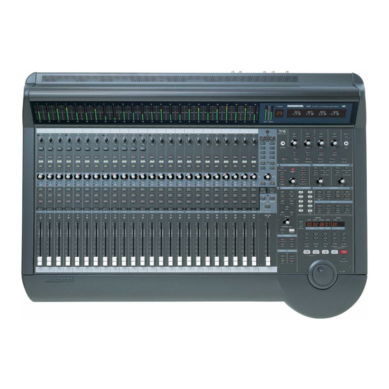
PWR DIST, 055-111-00
BACKPLANE BOARD, 055-163-00
OUTPUT CONTROL SURFACE
BOARD, 055-122-00
J35
NOT SHOWN:
VFD BOARD,
MIC/LINE METER BOARD, 055-108-00
LINE/MASTER METER BOARD,055-109-00
©1999 Mackie Designs Inc. All rights reserved
ANALOG I/O BOARD, 055-110-00
DCA BOARD, 055-112-00
CODEC BOARD, 055-113-00
DSP BOARD, 055-114-00
J28
J27
J26
LINE CONTROL SURFACE
BOARD, 055-121-00
J34
9 FADER BOARD
055-125-00
This file contains all 124 pages of 11" x 17" (to make it easier to print out)
J13
J12
J5
J32
Mrs. Zambeezie's BRAIN
BOARD, 055-136-00
J37
J36
J40
J39
8 FADER BOARD
055-124-00
BOARD LOCATION
J4
J7
J31
MIC CONTROL SURFACE
BOARD, 055-120-00
J38
8 FADER BOARD
055-124-00
JT 9/29/98
D-1
D8B
HOME
Advertisement

Related Manuals for Mackie D8B


Summary of Contents for Mackie D8B
-
Page 1: Board Location
NOT SHOWN: VFD BOARD, MIC/LINE METER BOARD, 055-108-00 LINE/MASTER METER BOARD,055-109-00 JT 9/29/98 This file contains all 124 pages of 11" x 17" (to make it easier to print out) BOARD LOCATION ©1999 Mackie Designs Inc. All rights reserved HOME... - Page 2 TAPE 9–16 TAPE 17–24 AUX SOLO 1 (of 8) ALT I/0 AUX 1 (of 8) MASTER LEVEL D / A AUX 1 – AUX 8 TO FX METER SELECT FX CARDS FLOW BLOCK DIAGRAM ©1999 Mackie Designs Inc. All rights reserved...
- Page 3 BOARD BLOCK DIAGRAM ©1999 Mackie Designs Inc. All rights reserved...
- Page 4 DCA 112 LINE/MASTER MIC CONTROL SURFACE METER 109 MIC/LINE METER108 CODEC 113 ANALOG I/O 110 8X FADER LINE CONTROL SURFACE BRAIN 136 9X FADER J47 J48 DSP 114 BOARD OUTLINES (not to scale) ©1999 Mackie Designs Inc. All rights reserved...
- Page 5 The circled numbers are the item numbers shown in the left column of the Parts list chapter on pages A10 and A11. CONSOLE ASSEMBLY DRAWINGS ©1998, ©1999 Mackie Designs Inc. All rights reserved...
- Page 6 The circled numbers are the item numbers shown in the left column of the Parts list chapter on pages A10 and A11. CONSOLE ASSEMBLY DRAWINGS ©1998, ©1999 Mackie Designs Inc. All rights reserved...
- Page 7 The circled numbers are the item numbers shown in the left column of the Parts list chapter on pages A10 and A11. CONSOLE ASSEMBLY DRAWINGS ©1998, ©1999 Mackie Designs Inc. All rights reserved...
- Page 8 The circled numbers are the item numbers shown in the left column of the Parts list chapter on pages A10 and A11. CONSOLE ASSEMBLY DRAWINGS ©1998, ©1999 Mackie Designs Inc. All rights reserved...
- Page 9 The circled numbers are the item numbers shown in the left column of the Parts list chapter on pages A12 and A13. REMOTE CPU ASSEMBLY DRAWINGS ©1998, ©1999 Mackie Designs Inc. All rights reserved...
- Page 10 The circled numbers are the item numbers shown in the left column of the Parts list chapter on pages A12 and A13. REMOTE CPU ASSEMBLY DRAWINGS ©1998, ©1999 Mackie Designs Inc. All rights reserved...
- Page 11 CONSOLE ASSEMBLY DRAWINGS ©1999 Mackie Designs Inc. All rights reserved...
- Page 12 CONSOLE ASSEMBLY DRAWINGS ©1999 Mackie Designs Inc. All rights reserved...
- Page 13 CONSOLE ASSEMBLY DRAWINGS ©1999 Mackie Designs Inc. All rights reserved...
- Page 14 CONSOLE ASSEMBLY DRAWINGS ©1999 Mackie Designs Inc. All rights reserved...
- Page 15 CONSOLE ASSEMBLY DRAWINGS ©1999 Mackie Designs Inc. All rights reserved...
- Page 16 CONSOLE ASSEMBLY DRAWINGS ©1999 Mackie Designs Inc. All rights reserved...
- Page 17 CONSOLE ASSEMBLY DRAWINGS ©1999 Mackie Designs Inc. All rights reserved...
- Page 18 CONSOLE ASSEMBLY DRAWINGS ©1999 Mackie Designs Inc. All rights reserved...
- Page 19 CONSOLE ASSEMBLY DRAWINGS ©1999 Mackie Designs Inc. All rights reserved...
- Page 20 F-10 CONSOLE ASSEMBLY DRAWINGS ©1999 Mackie Designs Inc. All rights reserved...
- Page 21 F-11 CONSOLE ASSEMBLY DRAWINGS ©1999 Mackie Designs Inc. All rights reserved...
- Page 22 F-12 CONSOLE ASSEMBLY DRAWINGS ©1999 Mackie Designs Inc. All rights reserved...
- Page 23 F-13 CONSOLE ASSEMBLY DRAWINGS ©1999 Mackie Designs Inc. All rights reserved...
- Page 24 F-14 CONSOLE ASSEMBLY DRAWINGS ©1999 Mackie Designs Inc. All rights reserved...
- Page 25 F-15 CONSOLE ASSEMBLY DRAWINGS ©1999 Mackie Designs Inc. All rights reserved...
- Page 26 F-16 CONSOLE ASSEMBLY DRAWINGS ©1999 Mackie Designs Inc. All rights reserved...
- Page 27 F-17 CONSOLE ASSEMBLY DRAWINGS ©1999 Mackie Designs Inc. All rights reserved...
- Page 28 F-18 CONSOLE ASSEMBLY DRAWINGS ©1999 Mackie Designs Inc. All rights reserved...
- Page 29 F-19 CONSOLE ASSEMBLY DRAWINGS ©1999 Mackie Designs Inc. All rights reserved...
- Page 30 F-20 ASSEMBLY DRAWINGS...
- Page 31 REMOTE CPU ASSEMBLY DRAWINGS ©1999 Mackie Designs Inc. All rights reserved...
- Page 32 REMOTE CPU ASSEMBLY DRAWINGS ©1999 Mackie Designs Inc. All rights reserved...
- Page 33 REMOTE CPU ASSEMBLY DRAWINGS ©1999 Mackie Designs Inc. All rights reserved...
- Page 34 REMOTE CPU ASSEMBLY DRAWINGS ©1999 Mackie Designs Inc. All rights reserved...
- Page 35 REMOTE CPU ASSEMBLY DRAWINGS ©1999 Mackie Designs Inc. All rights reserved...
- Page 36 REMOTE CPU ASSEMBLY DRAWINGS ©1999 Mackie Designs Inc. All rights reserved...
- Page 37 REMOTE CPU ASSEMBLY DRAWINGS ©1999 Mackie Designs Inc. All rights reserved...
- Page 38 REMOTE CPU ASSEMBLY DRAWINGS ©1999 Mackie Designs Inc. All rights reserved...
- Page 39 REMOTE CPU ASSEMBLY DRAWINGS ©1999 Mackie Designs Inc. All rights reserved...
- Page 40 G-10 REMOTE CPU ASSEMBLY DRAWINGS ©1999 Mackie Designs Inc. All rights reserved...
- Page 41 G-11 REMOTE CPU ASSEMBLY DRAWINGS ©1999 Mackie Designs Inc. All rights reserved...
- Page 42 G-12 REMOTE CPU ASSEMBLY DRAWINGS ©1999 Mackie Designs Inc. All rights reserved...
- Page 43 G-13 REMOTE CPU ASSEMBLY DRAWINGS ©1999 Mackie Designs Inc. All rights reserved...
- Page 44 CHANNEL 2 SHOWN CHANNEL 1 SHOWN CHANNEL 4 CHANNEL 3 CHANNEL 6 CHANNEL 5 CHANNEL 8 CHANNEL 7 CHANNEL 10 CHANNEL 9 CHANNEL 12 CHANNEL 11 1 SHEET 108-1 MIC/LINE METER BOARD 108 REV A ©1998 Mackie Designs Inc. All rights reserved...
- Page 45 108-2 MIC/LINE METER BOARD 108 REV A ©1998 Mackie Designs Inc. All rights reserved...
- Page 46 CHANNEL 5 POINT B, SEE TABLE CHANNEL 8 CHANNEL 7 (CH 1&2 SHOWN) CHANNEL 10 CHANNEL 9 CHANNEL 12 CHANNEL 11 MASTER RIGHT MASTER LEFT 1 SHEET 109-1 LINE/MASTER METER BOARD 109 REV A ©1998 Mackie Designs Inc. All rights reserved...
- Page 47 109-2 LINE/MASTER METER BOARD 109 REV A ©1998 Mackie Designs Inc. All rights reserved...
- Page 48 CH1 TO CH12 HAVE THE SAME DESIGN BUT THE REF DESIGNATORS DO NOT INCREASE NICELY BY THE 100'S. SEE THE NEXT SHEET FOR CH 3 TO 12 SHEET 1 OF 3 110-1 ANALOG I/O BOARD 110 REV B ©1998 Mackie Designs Inc. All rights reserved...
- Page 49 CHANNEL 3 CHANNEL 4 CHANNEL 5 CHANNEL 6 CHANNEL 7 CHANNEL 8 CHANNEL 9 CHANNEL 10 CHANNEL 11 CHANNEL 12 SHEET 2 OF 3 110-2 ANALOG I/O BOARD 110 REV B ©1998 Mackie Designs Inc. All rights reserved...
- Page 50 SHEET 3 OF 3 110-3 ANALOG I/O BOARD 110 REV B ©1998 Mackie Designs Inc. All rights reserved...
- Page 51 FB705 FB605 FB505 FB405 FB305 FB205 FB105 C106 FB49 FB51 FB58 FB57 FB59 C111 J1204 J1104 J1004 J904 J804 J704 J604 J504 J404 J304 J204 J104 110-4 ANALOG I/O BOARD 110 REV B ©1998 Mackie Designs Inc. All rights reserved...
- Page 52 +48V +12V +16V -16V Power distribution board 111 (inside console) 111-1 POWER DISTRIBUTION BOARD 111 REV B ©1998 Mackie Designs Inc. All rights reserved...
- Page 53 111-2 POWER DISTRIBUTION BOARD 111 REV B ©1998 Mackie Designs Inc. All rights reserved...
- Page 54 112-1 DCA BOARD 112 REV C ©1998 Mackie Designs Inc. All rights reserved...
- Page 55 112-2 DCA BOARD 112 REV C ©1998 Mackie Designs Inc. All rights reserved...
- Page 56 112-3 DCA BOARD 112 REV C ©1998 Mackie Designs Inc. All rights reserved...
- Page 57 112-4 DCA BOARD 112 REV C ©1998 Mackie Designs Inc. All rights reserved...
- Page 58 112-5 DCA BOARD 112 REV C ©1998 Mackie Designs Inc. All rights reserved...
- Page 59 112-6 DCA BOARD 112 REV C ©1998 Mackie Designs Inc. All rights reserved...
- Page 60 112-7 DCA BOARD 112 REV C ©1998 Mackie Designs Inc. All rights reserved...
- Page 61 112-8 DCA BOARD 112 REV C ©1998 Mackie Designs Inc. All rights reserved...
- Page 62 SEE SHEET 2 NOTE: THE CIRCUIT FOR U4 (WHICH IS FOR METER-LEFT AND METER-RIGHT) HAS PART NUMBERS WHICH DO NOT FOLLOW THE NORMAL 100, 200, 300 MACKIE WAY, SO THIS PARTICULAR CIRCUIT IS SHOWN ON SHEET 2 NOTE: LINE-13 TO LINE-24 CONNECT TO J3...
- Page 63 Sheet 2 of 4 113-2 CODEC BOARD 113 REV B ©1998 Mackie Designs Inc. All rights reserved...
- Page 64 THIS CIRCUIT IS REPEATED FOUR TIMES. THE REF DESIGNATORS AND LABEL DIFFERENCES BETWEEN THE FOUR CIRCUITS ARE SHOWN IN THE TABLE ABOVE U52 U152 U252 U352 Sheet 3 of 4 113-3 CODEC BOARD 113 REV B ©1998 Mackie Designs Inc. All rights reserved...
- Page 65 RESISTOR F (THE MIX AND SOLO CIRCUITS HAVE A SERIES RESISTOR HERE, 120 OHMS, SEE TABLE) U652 U452 U852 U752 U552 U1152 U952 U1052 Sheet 4 of 4 113-4 CODEC BOARD 113 REV B ©1998 Mackie Designs Inc. All rights reserved...
- Page 66 Rev B has these different parts, all other parts remain the same as Rev A. 113-5 CODEC BOARD 113 REV B ©1998 Mackie Designs Inc. All rights reserved...
- Page 67 113-6 CODEC BOARD 113 REV B ©1998 Mackie Designs Inc. All rights reserved...
- Page 68 C112 C122 C220 C137 C250 SHEET 1 OF 6 114-1 DSP BOARD 114 REV C ©1998 Mackie Designs Inc. All rights reserved...
- Page 69 C129 C108 SHEET 2 OF 6 114-2 DSP BOARD 114 REV C ©1998 Mackie Designs Inc. All rights reserved...
- Page 70 Points marked with an asterix also change label as shown in the table on the next page, the other points do not change label. As the 74AC32 is shared with two DSP channels, the pin-outs for D and C are like this: 114-3 DSP BOARD 114 REV C ©1998 Mackie Designs Inc. All rights reserved...
- Page 71 " " MIX_24 DTO_U24 DRO_U24 " " " " " U83C U83D U117 U115 " " R861 R865 R868 R866 R867 R888 R893 R889 R862 R863 R864 114-4 DSP BOARD 114 REV C ©1998 Mackie Designs Inc. All rights reserved...
- Page 72 U109 C204 C138 C121 C212 C139 C144 U114 C213 U112 C223 C207 C239 C242 C233 C234 C222 U117 C216 U115 C221 This pattern is repeated 24 times 114-5 DSP BOARD 114 REV C ©1998 Mackie Designs Inc. All rights reserved...
- Page 73 J47 J48 U46 U86 U89 U92 U95 U98 114-6 DSP BOARD 114 REV C ©1998 Mackie Designs Inc. All rights reserved...
- Page 74 114-7 DSP BOARD 114 REV C ©1998 Mackie Designs Inc. All rights reserved...
- Page 75 114-8 DSP BOARD 114 REV C ©1998 Mackie Designs Inc. All rights reserved...
- Page 76 115-1 DIGITAL I/O BOARD 115 REV E ©1998 Mackie Designs Inc. All rights reserved...
- Page 77 Top Traces Bottom Traces 115-2 DIGITAL I/O BOARD 115 REV E ©1998 Mackie Designs Inc. All rights reserved...
- Page 78 119-1 TAPE I/O BOARD 119 REV B ©1998 Mackie Designs Inc. All rights reserved...
- Page 79 119-2 TAPE I/O BOARD 119 REV B ©1998 Mackie Designs Inc. All rights reserved...
- Page 80 119-3 TAPE I/O BOARD 119 REV B ©1998 Mackie Designs Inc. All rights reserved...
- Page 81 119-4 TAPE I/O BOARD 119 REV B ©1998 Mackie Designs Inc. All rights reserved...
- Page 82 J4-33 FB40 J5-3 FB41 J5-6 FB46 J5-9 FB47 J5-12 FB52 J5-15 FB53 J5-18 FB58 J5-21 FB59 J5-24 FB64 J5-27 FB65 J5-30 FB70 J5-33 SHEET 1 OF 3 120-1 CONTROL SURFACE 120 REV A ©1998 Mackie Designs Inc. All rights reserved...
- Page 83 100s. Points marked with an asterix are shown in the tables, the other points do not change label. IN THE 2400'S R2429, D2401 SHEET 2 OF 3 120-2 CONTROL SURFACE 120 REV A ©1998 Mackie Designs Inc. All rights reserved...
- Page 84 SHEET 3 OF 3 120-3 CONTROL SURFACE 120 REV A ©1998 Mackie Designs Inc. All rights reserved...
- Page 85 C709 R731 R723 C716 R1929 R1928 R1927 R1926 R1925 R1924 R715 R704 R729 R1913 R1912 R1911 U1902 R1910 R713 C715 C811 R2016 R2021 R2020 R827 D807 L801 120-4 CONTROL SURFACE 120 REV A ©1998 Mackie Designs Inc. All rights reserved...
- Page 86 FB1202 C1210 U2401 R1225 U1201 FB1203 Q1202 C1209 R1231 R1223 R2429 R2428 R2427 R2426 R2425 R2424 R1215 C1206 R1229 U2402 R2413 R2412 R2411 C1216 R1204 R2410 R1213 120-5 CONTROL SURFACE 120 REV A ©1998 Mackie Designs Inc. All rights reserved...
- Page 87 A blank page. it couldn’t be helped 120-6 CONTROL SURFACE 120 REV A ©1998 Mackie Designs Inc. All rights reserved...
- Page 88 REF DESIGNATOR DIFFERENCES BETWEEN CHANNELS CHANNEL PARTS RANGE EXAMPLE IN THE 100'S R113, C102 SHOWN IN THE 200'S R213, C202 IN THE 1200'S R1213, C1202 SHEET 1 OF 4 121-1 CONTROL SURFACE 121 REV A ©1998 Mackie Designs Inc. All rights reserved...
- Page 89 R2029, D2001 Points marked with an asterix are shown in the tables, the other points do not change label. IN THE 2400'S R2429, D2401 SHEET 2 OF 4 121-2 CONTROL SURFACE 121 REV A ©1998 Mackie Designs Inc. All rights reserved...
- Page 90 SHEET 3 OF 4 121-3 CONTROL SURFACE 121 REV A ©1998 Mackie Designs Inc. All rights reserved...
- Page 91 SHEET 4 OF 4 121-4 CONTROL SURFACE 121 REV A ©1998 Mackie Designs Inc. All rights reserved...
- Page 92 R2002 C802 C803 C2008 R813 C2006 R814 U2001 R819 R820 U801 C807 R2029 R2028 R2027 R2026 R2025 R2024 R818 R817 U2002 R2013 R2012 R2011 C805 R2010 R2116 121-5 CONTROL SURFACE 121 REV A ©1998 Mackie Designs Inc. All rights reserved...
- Page 93 R2673 R2698 R2651 R2674 R2700 R2645 R2701 R2688 R2689 R2642 R2690 R2641 R2691 R2640 R2692 R2639 R2693 R2638 R2678 R2653 C2626 C2623 R2675 R2646 C2621 C2620 R2644 121-6 CONTROL SURFACE 121 REV A ©1998 Mackie Designs Inc. All rights reserved...
- Page 94 122-1 OUTPUT CONTROL SURFACE 122 REV A ©1998 Mackie Designs Inc. All rights reserved...
- Page 95 122-2 OUTPUT CONTROL SURFACE 122 REV A ©1998 Mackie Designs Inc. All rights reserved...
- Page 96 122-3 OUTPUT CONTROL SURFACE 122 REV A ©1998 Mackie Designs Inc. All rights reserved...
- Page 97 122-4 OUTPUT CONTROL SURFACE 122 REV A ©1998 Mackie Designs Inc. All rights reserved...
- Page 98 122-5 OUTPUT CONTROL SURFACE 122 REV A ©1998 Mackie Designs Inc. All rights reserved...
- Page 99 122-6 OUTPUT CONTROL SURFACE 122 REV A ©1998 Mackie Designs Inc. All rights reserved...
- Page 100 122-7 OUTPUT CONTROL SURFACE 122 REV A ©1998 Mackie Designs Inc. All rights reserved...
- Page 101 122-8 OUTPUT CONTROL SURFACE 122 REV A ©1998 Mackie Designs Inc. All rights reserved...
- Page 102 123-1 LINEAR POWER SUPPLY 123 REV A ©1998 Mackie Designs Inc. All rights reserved...
- Page 103 123-2 LINEAR POWER SUPPLY 123 REV A ©1998 Mackie Designs Inc. All rights reserved...
- Page 104 R203, C203 IN THE 800'S R803, C803 If you are partial, this is a partial pcb portion, the full pcb is shown elsewhere. SHEET 1 OF 2 124-1 8-WAY FADER 124 REV 3 ©1998 Mackie Designs Inc. All rights reserved...
- Page 105 SHEET 2 OF 2 124-2 8-WAY FADER 124 REV 3 ©1998 Mackie Designs Inc. All rights reserved...
- Page 106 124-3 8-WAY FADER 124 REV 3 ©1998 Mackie Designs Inc. All rights reserved...
- Page 107 124-4 8-WAY FADER 124 REV 3 ©1998 Mackie Designs Inc. All rights reserved...
- Page 108 ON/OFF_7 ON/OFF_8 ON/OFF_9 FADER PARTS RANGE EXAMPLE IN THE 100'S R3, C3 SHOWN IN THE 200'S R203, C203 IN THE 800'S R803, C803 SHEET 1 OF 2 125-1 9-WAY FADER 125 REV 3 ©1998 Mackie Designs Inc. All rights reserved...
- Page 109 SHEET 2 OF 2 125-2 9-WAY FADER 125 REV ©1998 Mackie Designs Inc. All rights reserved...
- Page 110 125-3 9-WAY FADER 125 REV 3 ©1998 Mackie Designs Inc. All rights reserved...
- Page 111 125-4 9-WAY FADER 125 REV ©1998 Mackie Designs Inc. All rights reserved...
- Page 112 136-1 BRAIN BOARD 136 REV A ©1998 Mackie Designs Inc. All rights reserved...
- Page 113 136-2 BRAIN BOARD 136 REV A ©1998 Mackie Designs Inc. All rights reserved...
- Page 114 136-3 BRAIN BOARD 136 REV A ©1998 Mackie Designs Inc. All rights reserved...
- Page 115 136-4 BRAIN BOARD 136 REV A ©1998 Mackie Designs Inc. All rights reserved...
- Page 116 136-5 BRAIN BOARD 136 REV A ©1998 Mackie Designs Inc. All rights reserved...
- Page 117 136-6 BRAIN BOARD 136 REV A ©1998 Mackie Designs Inc. All rights reserved...
- Page 118 163-1 EFX BACKPLANE 163 REV B ©1998 Mackie Designs Inc. All rights reserved...
- Page 119 163-2 EFX BACKPLANE 163 REV B ©1998 Mackie Designs Inc. All rights reserved...
- Page 120 163-3 EFX BACKPLANE 163 REV B ©1998 Mackie Designs Inc. All rights reserved...
- Page 121 163-4 EFX BACKPLANE 163 REV B ©1998 Mackie Designs Inc. All rights reserved...
- Page 122 164-1 CLOCK CARD 164 REV C ©1998 Mackie Designs Inc. All rights reserved...
- Page 123 164-2 CLOCK CARD 164 REV C ©1998 Mackie Designs Inc. All rights reserved...
- Page 124 201-1 POWER DISTRIBUTION 201 REV A ©1998 Mackie Designs Inc. All rights reserved...
- Page 125 Another one of those blank pages. Actually, they serve a purpose, which is to make the beginning of each new board chapter start on a right hand page. 201-2 POWER DISTRIBUTION 201 REV A ©1998 Mackie Designs Inc. All rights reserved...
Need help?
Do you have a question about the D8B and is the answer not in the manual?
Questions and answers