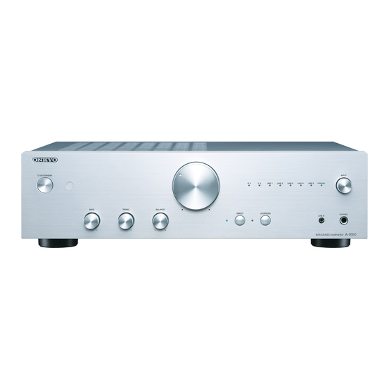
Summary of Contents for Onkyo A-9010
-
Page 1: Integrated Amplifier
A-9010 Ref. No. 4516 032015 042015(WMB) INTEGRATED AMPLIFIER A-9010(B)/(S) MODEL Black and Silver models RC-902S B WMP B WMB 220-240V AC, 50/60Hz S WMP B WDC 120V AC, 60Hz S WJJ 100V AC, 50/60Hz... -
Page 2: Service Procedure
A-9010 SERVICE PROCEDURE INITIAL SETTING FOR SHIPPING Initialization of memories. Hold down [DIRECT button and then press [ON/STANDBY] button. Unplug the power cord after it goes standby mode. -
Page 3: Adjustment Procedure
A-9010 ADJUSTMENT PROCEDURE Idling Current When 1. Exchange the transistor (Q308-Q310, Q315, Q316, Q408-Q410, Q415, Q416). 2. Exchange the Main PC board. 3. Exchange the Power transformer (main). Setting position BASS, TREBLE and BALANCE: Center. VOLUME: Minimum. Procedure a. Pre-adjustment Set the following registers to minimum position before POWER ON. -
Page 4: Exploded View
A-9010 EXPLODED VIEW - 1/2 (B): Black FUSE LABEL , HOT... - Page 5 A-9010 EXPLODED VIEW - 2/2 (S): Silver FUSE LABEL , HOT (Except WJJ)
- Page 6 A-9010 Schematic diagram...
-
Page 7: Schematic Diagram
A-9010 Schematic diagram M AIN TRANS JW 191_ 7.92-02P BO X JW 192_ RED#22*2 120mm CJP02G A89ZY BLACK#22*2 120mm CN191 CUP12710Z-3 VO LUM E PART R1501 CUP12710Z-2 AV3.3V HEADPHO NE PART Q 1927 L1501 KTC1027Y HP-LIN + 5V R1401 BK195 BK196 + 10.5V... - Page 8 A-9010 Schematic diagram TO M CU PO W ER B'D M AIN B'D < = = > FRO NT B'D 2.0-07P BO ARD-IN CJP23G A115ZY CJP13G A115ZY -W DC/W M P CW B1C00730047 BN195 CN301 CN302 RT1N141C : R1= 10K, R2= 10K...
- Page 9 A-9010 Schematic diagram...
-
Page 10: Exploded View Parts List
LABEL , HOT (CAUTION) 29392531 LABEL , SPEAKER A-9010 VQB1A1389Z FUSE(S506 Series, 250V,3.15A) CBA2C3150TLEC [TRANS COIL] TRANS , POWER, A-9010 CLT5R047ZU [TUNER UNIT] A-9010 WDC FRONT PCB ASS'Y * (Parent) COP12710C 25-1 FRONT PCB (Child) COP12710C-1 25-2 INPUT PCB (Child) COP12710C-2... -
Page 11: Pc Board Parts List
2/2 PAGE A-9010(B)WDC PC BOARD PARTS LIST : NSP CIRCUIT NO. PART NAME DESCRIPTION Q'TY PART NO. (SN) REMARKS [SEMI CONDUCTOR] C157 CAP, ELECT (47uF/50V, 8X11.5_FG) (for audio) CCEA1HFG470T C257 CAP, ELECT (47uF/50V, 8X11.5_FG) (for audio) CCEA1HFG470T C302 CAP, ELECT (47uF/50V, 8X11.5_FG)


Need help?
Do you have a question about the A-9010 and is the answer not in the manual?
Questions and answers